Digital Data Transmission Using A Low Voltage Power Line
Digital Data Transmission Using A Low Voltage Power Line
Digital Data Transmission Using A Low Voltage Power Line

Create successful ePaper yourself
Turn your PDF publications into a flip-book with our unique Google optimized e-Paper software.
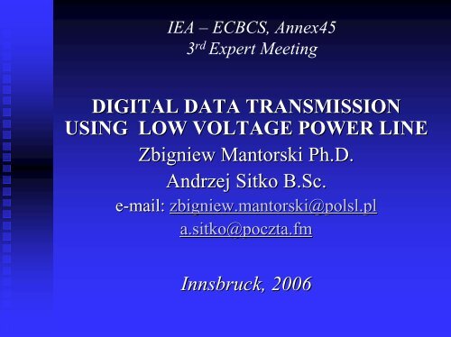
IEA – ECBCS, Annex453 rd Expert MeetingDIGITAL DATA TRANSMISSIONUSING LOW VOLTAGE POWER LINEZbigniew Mantorski Ph.D.Andrzej Sitko B.Sc.e-mail:zbigniew.mantorski@polsl.pla.sitko@poczta.fmInnsbruck, 2006
<strong>Low</strong> voltage power line as thetransmission mediumInteraction between the power line componentsinfluents data transmission possibilities.•<strong>Power</strong> <strong>Power</strong> line impedance•Disturbances•Standing Standing waves•<strong>Transmission</strong>range
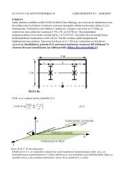
<strong>Power</strong> line impedance• Big range of the network impedance changesfor the given frequency.• <strong>Power</strong> line works as filter.• Correct data transmission when the voltageoutput level of the transmitter is not far to thevoltage input level of the receiver. It can beachieved when the filter attenuation is low.• <strong>Low</strong> attenuation when high value of the parallelfilter impedance. <strong>Power</strong> line impedance mightbe to low to get connection.levelU=20 log⎛⎜⎝U1µ V⎞⎟⎠Att= 20log⎛⎜⎜⎝U outtransU in rec⎞⎟⎟⎠
Distortion Sources•LightingLighting dimmers•RTV RTV equipment•Electronicpower supply units•PC PC computers•Compact Compact fluorescent lamps (ballasts)•<strong>Power</strong> <strong>Power</strong> electronic converters•Switches, Switches, small universal motors, fluorescentlamps.EMC filters reduce distortions but the power lineimpedance in the transmission band decreases.
Standing waves and transmissionrange• In Home Automation wave phenomena can beneglected. <strong>Transmission</strong> range might be up to tensmeters.• In PLC (<strong>Power</strong> <strong>Line</strong> Communication) installation- transmission band is in MHz - when the receiveris in standing wave node receiving signals isimpossible. <strong>Transmission</strong> range might be up toseveral hundred meters.
Choice of the transmission system:•priceprice of the system,•controlcontrol equipment complexity,•quantity quantity and kind of the necessary externalelements,•transmissionquality.<strong>Transmission</strong> system has to be in conformitywith the European standards, especially withEN 50065.
Block diagram of the transmissiondeviceSNAP – Scaleable Node Address Protocol, SPI – Serial PeripheralInterface, PSU –<strong>Power</strong> Supply Unit
Prototype transmission device• Prototypedevice consists of two pieces: analogue modembuilt on the base of the transmission module AVT-5085and digital controller built on the base of themicrocontroller ATMEGA8.• The software for the controller was designed with theassembler AVR and Atmel programme AVR Studio 4. Toachieve higher speed it was divided into several folders.<strong>Data</strong> are read and written through the serial port USART(bus RS-232C). The communication between the receiverand transmitter is realised through “virtual serial port” withthe SNAP protocol. The “repetition mechanism” is alsoincluded.
<strong>Data</strong> <strong>Transmission</strong>A) without distortion, B) with data package distortionCRC – Cyclic Redundancy Check, ACK – Acknowledge Character,NAK– Negative-Acknowledge Character DTE – <strong>Data</strong> TerminalEquipment
<strong>Data</strong> <strong>Transmission</strong> (cont.)Another possible distortions:• to high attenuation during data packagetransmitting,• distortion of the ACK package,• to high attenuation during ACK packagetransmitting,• distortion of the data package and to highattenuation during ACK package transmitting,• distortion of the data and ACK packages.
Tests results• Tests were carried out in the one-family house.• Sockets were supplied from single-phase line.• First results– negative because to high signalattenuation.• Identification of the low impedance loads:- RTV equipment: TV sets (input filter with teen-nFnFcondenser), satellite tuner (electronic(PSU),- compact fluorescent lamps with EMC filter.• Any of the domestic appliances (fridge, mixer, mincer,coffee-mill) had negative influence into correct datatransmission.• After separation of the low impedance loads with thereactor, results were positive and all data weretransmitted.
Conclusion• <strong>Transmission</strong> speed in Homeautomatics – depends to howmany bytes of data have to be send. Usually from severalto tens bytes. <strong>Transmission</strong> process consists of someconfiguration bytes, data bytes and “shake-hand”information from the receiver.• In the described case number of the data bytes was limitedto 8, but the package might be increased. SNAP protocol isenough flexible to do it. Before any changes, there shouldbe taken under consideration, that there is appliedasynchronic transmission and that there exists anysynchronization signal. Transmitter and receiver have ownnon-synchronised clocks and differences between themmight be neglected only when the number of data bytes issmall.• Because of the main advantage – lack of the additionalwiring - the low-band transmission can be applied in HomeAutomationand in lighting control in buildings.