Homebrew and Experimenters Group HF 1:1 (Choke) Balun Kit ...
Homebrew and Experimenters Group HF 1:1 (Choke) Balun Kit ...
Homebrew and Experimenters Group HF 1:1 (Choke) Balun Kit ...

Create successful ePaper yourself
Turn your PDF publications into a flip-book with our unique Google optimized e-Paper software.
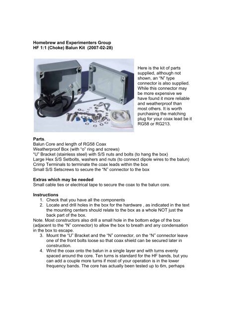
<strong>Homebrew</strong> <strong>and</strong> <strong>Experimenters</strong> <strong>Group</strong><strong>HF</strong> 1:1 (<strong>Choke</strong>) <strong>Balun</strong> <strong>Kit</strong> (2007-02-28)Here is the kit of partssupplied, although notshown, an N typeconnector is also supplied.While this connector maybe more expensive wehave found it more reliable<strong>and</strong> weatherproof thanmost others. It is worthpurchasing the matchingplug for your coax lead be itRG58 or RG213.Parts.<strong>Balun</strong> Core <strong>and</strong> length of RG58 CoaxWeatherproof Box (with o ring <strong>and</strong> screws)U Bracket (stainless steel) with S/S nuts <strong>and</strong> bolts (to hang the box)Large Hex S/S Setbolts, washers <strong>and</strong> nuts (to connect dipole wires to the balun)Crimp Terminals to terminate the coax leads within the boxSmall S/S Setscrews to secure the N connector to the boxExtras which may be neededSmall cable ties or electrical tape to secure the coax to the balun core.Instructions1. Check that you have all the components2. Locate <strong>and</strong> drill holes in the box for the hardware , as indicated in the textthe mounting centers should relate to the box as a whole NOT just theback part of the box.Note. Most constructors also drill a small hole in the bottom edge of the box(adjacent to the N connector) to allow the box to breath <strong>and</strong> any condensationin the box to escape.3. Mount the U Bracket <strong>and</strong> the N connector, on the N connector leaveone of the front bolts loose so that coax shield can be secured later inconstruction.4. Wind the coax onto the balun in a single layer <strong>and</strong> with turns evenlyspaced around the core. Ten turns is st<strong>and</strong>ard for the <strong>HF</strong> b<strong>and</strong>s, but youcan add a couple more turns if most of your operation is in the lowerfrequency b<strong>and</strong>s. The core has actually been tested up to 6m, perhaps
only 8 turns to bias it s operation in the higher frequency <strong>HF</strong> b<strong>and</strong>s <strong>and</strong>6m. Use electrical tape or small cable ties to secure the coax to the balun.5. Place wound balun core temporarily into the box <strong>and</strong> orientate the coaxends so that one end goes to the N connector <strong>and</strong> the other will go to theDipole Terminals (not fitted yet).6. Mark <strong>and</strong>/or cut to length the coax ends, make sure you leave enoughlength so that :a. The N connector end is long enough so that when the core <strong>and</strong>shield are separated, the shield is long enough to reach the looseconnector mounting bolt.b. The Dipole Terminal end is long enough so that when core <strong>and</strong>shield are separated the core AND the shield are long enough toreach the terminals in the side of the case.7. Terminate the coax (remove balun from box as necessary) :a. At the N connector end remove the unwanted cable sheath(careful so that you don t nick the core of the shield), trim core tolength <strong>and</strong> strip a short length of insulation off so that it fits into theN connector center spigot. Carefully twist the shield wire togetherto form a single wire, check it s fit to the connector mounting bolt,trim to length <strong>and</strong> fit a crimp connector to the shield wire (shortends)b. At the Dipole Terminal end of the coax, remove sufficient cablesheath so that the core <strong>and</strong> the shield are the same length <strong>and</strong>reach the terminals easily. Strip a short length of insulation from thecore <strong>and</strong> fit a crimp connector to it. Carefully twist the shield wiretogether to form a single wire, check it s fit to the terminal bolt, trimto length <strong>and</strong> fit a crimp connector to the shield wire (long ends).8. Check electrical continuity of core (one end to the other) <strong>and</strong> shield (oneterminal to the other) <strong>and</strong> check that there are no shorts between the core<strong>and</strong> the shield. This can happen where you cut off the coax sheath, if youcut too deep the str<strong>and</strong>s of the shield can find their way down to the centrewire of the core. You definatly don t want an intermittent connection inyour balun when it is hung up in the air.9. Place the wound balun core back into the box <strong>and</strong> orient it so that theends of the coax reach their appropriate terminations.10. Put one of the Dipole Terminal bolts through one of the terminated longends, then through it s hole in the side of the box, then a washer <strong>and</strong> aspring/star washer, then a nut <strong>and</strong> tighten with your fingers.11. Repeat this process for the other long end of the coax to the other side ofthe box.Note. It does not matter which terminal the core or shield goes to so long as eachterminal has a wire on it.12. Now go to the short end of the coax <strong>and</strong> secure the terminated shield tothe loose bolt on the N connector, again just h<strong>and</strong> tight for the timebeing.13. Now before tightening everything up, we do a continuity check again
a. Should be ZERO ohms between the center of the N connector<strong>and</strong> the terminated core lead going to one of the Dipole Terminalsb. Should be ZERO ohms between the N connector body <strong>and</strong> theterminated shield wire going to the other Dipole Terminal.c. Should be OPEN CIRCUIT between the center spigot <strong>and</strong> the bodyof the N connector, also between the two Dipole Terminals.14. Now tighten all the bolts <strong>and</strong> terminals up, nice <strong>and</strong> tight but don t squashthe plastic box <strong>and</strong> be careful not to pull the terminated ends of the coax.15. Center up the balun core in the bottom section of the box <strong>and</strong> secure itwith a few blobs of hot glue or Selastic TM , when it has cooled/dried fit theO ring in the groove <strong>and</strong> fit the lid with it s screws.Above is a diagramic view of the kit when assembled <strong>and</strong> also a picture of acompleted unit.
Using the <strong>Balun</strong>Into an existing dipole antenna:Simply drop the center of the antenna, remove the center insulator <strong>and</strong> terminatethe dipole ends to the baluns Dipole Terminals. Terminate a length of coax(RG58 or RG213) with an N plug <strong>and</strong> fit it to the balun N connector. Usingsome heavy tape, plastic rope or a couple of cable ties around the box, securethe dipole wires to the box, this takes the strain off the Dipole Terminals. Raisethe antenna again, terminate the other end of the coax <strong>and</strong> check the antennasoperation (see tuning the antenna in the following section).A new dipole antenna:Basically an antenna should be as high in the air as you can practically get it. Fora dipole you will need at least one high point to haul the balun box up to. Theends of the dipole sections should be just as high if you can. The box <strong>and</strong> thedipole ends should of course be spaced away from <strong>and</strong> insulated from anystructure or pole/tree. Sorry the subject of designing an antenna <strong>and</strong> it splacement is well beyond these simple instructions, do the best you can with thespace <strong>and</strong> structures available. There is plenty of information in books, manuals<strong>and</strong> on the WEB.Tuning the antenna:For the b<strong>and</strong> you wish to use determine the length of each section of the dipole<strong>and</strong> add a bit more length, say 5% or 10% more. Most use what is generallycalled insulated building wire , this is usually strong enough for at least an 80mdipole. Terminate <strong>and</strong> secure the dipole sections to the balun Dipole Terminals.Terminate a length of coax (RG58 or RG213) with an N plug <strong>and</strong> fit it to thebalun N connector. Using some heavy tape, plastic rope or a couple of cableties around the box, secure the dipole wires to the box, this takes the strain offthe Dipole Terminals. Raise the antenna, terminate the other end of the coax <strong>and</strong>check the antennas operation (see tuning the antenna in the following section).Then using either an Antenna Bridge or a Transmitter (on low power) <strong>and</strong> a SWRmeter check the operation of the antenna. You will most likely find it is too long,simply drop the ends <strong>and</strong> chop off a small section of each end (same length bothends), raise the ends again <strong>and</strong> test the antenna. Keep doing this <strong>and</strong> choppingoff shorter <strong>and</strong> shorter lengths until the antenna is the correct length. If it is apermanent installation perhaps leave it a bit long <strong>and</strong> come back a few days laterwhen the wire has settled in (stretched) <strong>and</strong> re-check it s operation, adjusting ifnecessary. Don t worry about the loose ends, just leave them hang there, so longas they are well up in the air.Happy <strong>Homebrew</strong>ing, please contact us if you have any problems.