Product Manual 128 PQC Series Control Valve 1" 1500 lbs
Product Manual 128 PQC Series Control Valve 1" 1500 lbs
Product Manual 128 PQC Series Control Valve 1" 1500 lbs
- No tags were found...

You also want an ePaper? Increase the reach of your titles
YUMPU automatically turns print PDFs into web optimized ePapers that Google loves.
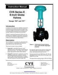
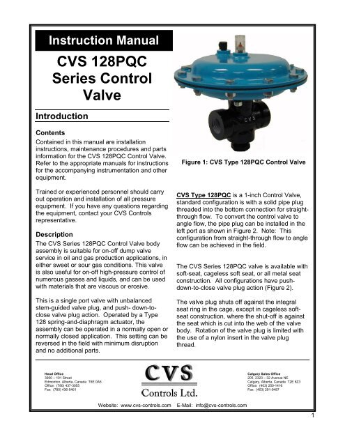
Instruction <strong>Manual</strong>CVS <strong>128</strong><strong>PQC</strong><strong>Series</strong> <strong>Control</strong><strong>Valve</strong>IntroductionContentsContained in this manual are installationinstructions, maintenance procedures and partsinformation for the CVS <strong>128</strong><strong>PQC</strong> <strong>Control</strong> <strong>Valve</strong>.Refer to the appropriate manuals for instructionsfor the accompanying instrumentation and otherequipment.Trained or experienced personnel should carryout operation and installation of all pressureequipment. If you have any questions regardingthe equipment, contact your CVS <strong>Control</strong>srepresentative.DescriptionThe CVS <strong>Series</strong> <strong>128</strong><strong>PQC</strong> <strong>Control</strong> <strong>Valve</strong> bodyassembly is suitable for on-off dump valveservice in oil and gas production applications, ineither sweet or sour gas conditions. This valveis also useful for on-off high-pressure control ofnumerous gasses and liquids, and can be usedwith materials that are viscous or erosive.This is a single port valve with unbalancedstem-guided valve plug, and push- down-toclosevalve plug action. Operated by a Type<strong>128</strong> spring-and-diaphragm actuator, theassembly can be operated in a normally open ornormally closed application. This setting can bereversed in the field with minimum disruptionand no additional parts.Figure 1: CVS Type <strong>128</strong><strong>PQC</strong> <strong>Control</strong> <strong>Valve</strong>CVS Type <strong>128</strong><strong>PQC</strong> is a 1-inch <strong>Control</strong> <strong>Valve</strong>,standard configuration is with a solid pipe plugthreaded into the bottom connection for straightthroughflow. To convert the control valve toangle flow, the pipe plug can be installed in theleft port as shown in Figure 2. Note: Thisconfiguration from straight-through flow to angleflow can be achieved in the field.The CVS <strong>Series</strong> <strong>128</strong><strong>PQC</strong> valve is available withsoft-seat, cageless soft seat, or all metal seatconstruction. All configurations have pushdown-to-closevalve plug action (Figure 2).The valve plug shuts off against the integralseat ring in the cage, except in cageless softseatconstruction, where the shut-off is againstthe seat which is cut into the web of the valvebody. Rotation of the valve plug is limited withthe use of a nylon insert in the valve plugthread.Head Office3900 – 101 StreetEdmonton, Alberta, Canada T6E 0A5Office: (780) 437-3055Fax: (780) 436-5461Calgary Sales Office205, 2323 – 32 Avenue NECalgary, Alberta, Canada T2E 6Z3Office: (403) 250-1416Fax: (403) 291-9487Website: www.cvs-controls.comE-Mail: info@cvs-controls.com1
Description continued,Any process leakage passing through thepacking is permitted to escape through a leakoffvent which passes through the packing box andout the valve body. This prevents any leakagefrom passing along the stem into the actuatorand also prevents loading pressure leakagefrom the lower diaphragm from reaching thevalve body through the stem.Warning:The leakoff vent must be kept open at alltimes. Flammable or other hazardous fluidsshould be vented into an open, well-ventilatedarea to prevent fire or explosion.Table 1: SpecificationsFactory-set specifications for your individual CVS <strong>128</strong><strong>PQC</strong> <strong>Control</strong> <strong>Valve</strong> are stamped on thenameplate, located on the upper diaphragm casing.End Connection Style CVS Type <strong>128</strong> <strong>PQC</strong> 1-inch NPT FemalePort DiametersMaximum Inlet Pressures andTemperatures**Maximum Pressure Drops** See Table 2Actuator Operating PressuresMaximum Actuator CasingPressureShutoff ClassificationsMaterial TemperatureCapabilitiesFlow CharacteristicFlow DirectionIn 1/4, 3/8, 1/2Metal SeatCVS Typemm 6.4, 9.5, 12.7<strong>128</strong><strong>PQC</strong>In 1/4, 3/8, 1/2, 3/4*Soft Seatmm 6.4, 9.5, 12.7, 19.1*-20 o F to +100 o F (-29 o C to 38 o C) 3600 psig (248 bar)+150 o F (+66 o C) 3550 psig (245 bar)+180 o F (+82 o C) 3520 psig (243 bar)20 psig (1.4 bar) or 35 psig (2.4 bar)100 psig (6.9 bar)ANSI Class IV ANSI/FCI 70-2-1998 – 0.01 percent ofMetal Seatmaximum valve capacity using air at a pressure drop of 50 psi(3.4 bar, differential), at 50 o F to 125 o F (10 o C to 52 o C)ANSI Class IV ANSI/FCI 70-2-1998 – Less than one bubbleSoft Seatper minute (0.15 ml) per minute using air at a pressure drop of50 psi (3.4 bar, differential) at 50 o F to 125 o F (10 o C to 52 o C)Metal Seat -20 o F to +180 o F (-29 o C to +82 o C)Soft Seat -20 o F to +150 o F (-29 o C to +55 o C)Quick opening with 45-degree taper valve plugEither directionMaximum Rated Travel3/8 inches (10mm)Actuator Diaphragm EffectiveArea33 inches 2 (213 cm 2 )Actuator Pressure Connection 1/4-inch NPT Female<strong>Valve</strong> Travel Indication<strong>Valve</strong> travel is indicated on plastic indicator cover with scale divisions indicated every 25 percentof travel.Approximate Weight CVS Type <strong>128</strong> <strong>PQC</strong> 17 lb (7.7 kg)* Cageless construction with seat cut into body** Pressure and temperature restrictions outlined in this guide, along with any applicable code limitation, should not be exceeded2
InstallationWarning:Service conditions must not exceed the limitsshown on the valve nameplate, or thoseoutlined in this manual. Consequences couldinclude bursting of pressure-retaining partsand uncontrolled process fluid, resulting inpersonal injury or property damage. <strong>Control</strong>valves should also be protected from externaldamages.Prior to installing the CVS <strong>Series</strong> <strong>128</strong><strong>PQC</strong><strong>Control</strong> <strong>Valve</strong>, perform a complete inspection fordamage, and remove any foreign debris.Position the valve for desired flow direction. Ifangle flow is required, switch the pipe plug toleft-hand connection. (Figure 2)The versatility of this valve allows for installationin any orientation, with the standard methodbeing with the actuator above the body.Standard orientation is best when an angle bodyor angle configuration has been specified.When installing the valve into the line, acceptedpiping practices must be used. A three-valvebypass should be used if continuous operationis required during inspection or maintenance.For a fail-close control valve, connect the inputsignal line into the 1/4-inch NPT actuatorconnection (Figure 2) in the lower diaphragmcase assembly. The input signal pressure lineshould be installed in the upper diaphragm caseassembly of a fail-open control valve.CVS Type <strong>128</strong><strong>PQC</strong> <strong>Control</strong> <strong>Valve</strong> with Fail-Close ActionDetail of CVS Type<strong>128</strong><strong>PQC</strong> ExteriorFigure 2: CVS Type <strong>128</strong><strong>PQC</strong> <strong>Control</strong> <strong>Valve</strong> Typical Constructions3
MaintenanceWarning:Prior to performing any maintenance, isolatethe valve from the process pressure. Ventcontrol input signal pressure. Relieve theprocess pressure and drain process mediafrom both sides of valve (Figure 5, Key 27). Asudden release of pressure or fluid can causepersonal injury or property damage.Scheduled inspections and maintenance arevital to continued operation of all pressurecontrol valves and systems. Parts are subjectto wear and tear, and must be replaced asnecessary, depending on the intensity of serviceconditions. Unless the valve body requiresmaintenance or replacement, it may remain inthe pressure system or on the vessel.Replacing Packing and TrimFollow these procedures when replacing theentire packing and trim assembly or individuallyreplacing packing and trim parts. Unlessotherwise indicated, key numbers in this sectionreference Table 3 for parts listings forreplacement packing and trim assembly, Figure3 for packing and trim assembly key numbersand Figure 5 control valve assembly keynumbers.1. Detach the control valve from all pressure,and release pressure from valve body andactuator. Ensure the valve is completelyclosed.2. Remove the four nuts (Key 32) from thescrews of the lower diaphragm casing. Afterdisconnecting the input signal tubing,remove the actuator from the valve body,along with attached trim parts.Table 2: Maximum Allowable Shutoff Pressure DropsSeatingMetal(AllTypes)SoftActuatorActionFailCloseFailOpenFailCloseFailOpenFlowingPressureDropTendsTo:Open<strong>Valve</strong>Close<strong>Valve</strong>Close<strong>Valve</strong>Open<strong>Valve</strong>Close<strong>Valve</strong>Close<strong>Valve</strong>PortDiameterInmmCadmium Coloured Main SpringCVS14A8831X012At 20 Psig (1.4 At 35 Psig (2.4bar) Operating bar) OperatingSignal Pressure Signal Pressure(2 Springs Req’d) (4 Springs Req’d)At 20 Psig (1.4bar) OperatingSignal Pressure(2 Springs Req’d)Red Main SpringCVS14A9077X012At 35 Psig (2.4bar) OperatingSignal Pressure(4 Springs Req’d)Psi Bar Psi Bar Psi Bar Psi Bar1/4 6.4 1510 104 3370 232 3380 233 3600 2483/8 9.5 520 36 1340 92 1340 92 3120 2151/2 12.7 220 15 690 47 700 48 1720 1183/4 19.1 30 2.1 240 16 240 16 710 491/4 6.4 940 65 1860 <strong>128</strong> 1370 94 2920 2013/8 9.5 1130 78 2450 169 1540 106 3300 2271/2 12.7 1330 92 2920 201 1710 118 3600 2483/4 19.1 2030 140 3600 248 2320 160 3600 2481/4 6.4 170 12 350 24 --- --- --- ---3/8 9.5 530 36 610 42 --- --- --- ---1/2 12.7 540 37 1150 79 --- --- --- ---3/4 19.1 1400 96 2910 200 --- --- --- ---1/4 6.4 1000 69 1000 69 1000 69 1000 693/8 9.5 710 49 1000 69 1000 69 1000 691/2 12.7 400 28 830 57 830 57 1000 693/4** 19.1** 160 11 350 24 360 25 790 541/4 6.4 940 65 1000 69 1000 69 1000 693/8 9.5 1000 69 1000 69 1000 69 1000 691/2 12.7 1000 69 1000 69 1000 69 1000 693/4** 19.1** 1000 69 1000 69 1000 69 1000 691/4 6.4 560 39 660 45 --- --- --- ---3/8 9.5 480 33 960 66 --- --- --- ---1/2 12.7 540 37 1000 69 --- --- --- ---3/4** 19.1** 1000 69 1000 69 --- --- --- ---* Contact CVS <strong>Control</strong>s for pressure drop** Available in 1-inch CVS <strong>Control</strong>s <strong>128</strong> <strong>PQC</strong> valves as a cageless construction with the seat cut into the body4
Replacing Packing and Trim continued,3. Accessible areas should be cleaned at thisstage, and all necessary maintenanceperformed. The actuator and attached trimparts can be turned over and held by thevalve body.4. To separate trim and access packing partsor seal O-rings, first loosen and remove thevalve plug (Key 25) and remove the packingbox washer (Key 27).5. Remove the packing box (Key 28), O-ringretainer (Key 18), stem O-ring (Key 19) anddiaphragm casing O-ring (Key 31) off thestem.6. Install replacement parts as necessary.6.1. If a complete packing and trimassembly is being installed, remove theassembly from the tube (Key 37),keeping the web sleeve (Key 39) on theassembly so the parts remain in place.Roll the sleeve back as necessaryduring installation.6.2. Continue pushing the assembly ontothe stem until the valve plug and cageare pushed away from the packing boxwasher or wiper ring. Roll the websleeve back into place just past thepacking box.6.3. If installing nitrile/cotton packing, thepacking rings may be lubricated withsilicon based product.7. Slide the packing box onto the stem until thepacking box, the O-ring (Key 19) and the O-ring retainer (Key 18) and the diaphragmcasing O-ring (Key 31) are sealed againstthe diaphragm casing.7.1. Ensuring proper positioning of the O-rings will prevent them from being cutwhen other parts are compressedagainst them.7.2. Advance the packing spring washer(Key 29) , packing spring (Key 21),second packing spring washer, wiperring and packing box washer (Key 27, ifincluded in the assembly) down ontothe stem.8. For installation of the packing and trimassembly, it is necessary to remove thesleeve, cage puller (Key 40) and cage (Key23) from the valve plug depending onindividual valve configuration.9. Fix the valve plug onto the stem, rotating theplug until the shoulder makes snug contactwith the stem. No further tightening isnecessary.10. To replace the cage or access the cage O-ring(Key 22), remove the cage from the body (Key26) using the cage puller or a wire hook.Replacement parts can be installed asnecessary.11. Attach the actuator and trim to the valve body(Key 26), paying special attention to the cageO-ring to prevent damage. Thread the fournuts (Key 32) to the lower diaphragm casingassembly screws. Nuts must be tightened to15-foot-pounds (20N• m).12. Reconnect the input signal tubing to theactuator connection of the appropriatediaphragm casing.Figure 3: Replacement Packing and TrimAssemblies for Metal SeatedConstructions5
Changing Main Spring RangeUnless otherwise indicated, refer to Table 3 forparts listings for replacement packing and trimassembly, Figure 3 for packing and trimassembly key numbers and Figure 5 for controlvalve assembly key numbers.1. Isolate off the control valve from allpressure, and release pressure from valvebody and actuator.2. Release pressure and drain the processmedia from both sides of the valve body.Ensure the valve is completely closed.3. If necessary, disconnect the input signaltubing; remove the diaphragm casing nuts(Key 15), cap screws (Key 14) and upperdiaphragm casing (Key 1).4. For fail-close action applications, installmain springs (Key 12), using quantities anddescriptions as outlined in Table 2.Note: It is important to avoid loosening thestem-nut (Key 15), as this may prevent thevalve from shutting off or from fully openingat full pressure, and resulting in the need forcomplete disassembly of the control valve toproperly install the stem and diaphragm.5. For fail-open applications, unfasten thelocknut (Key 16), remove the flat washer(Key 33), diaphragm (Key 35), diaphragmplate (Key 34), spring plate (Key 2), andmain springs (Key 12).6. Refer to Table 2 and install main springs asindicated.7. Reassemble the removed parts (Keys 2, 34,35, 33, and 16). The locknut (Key 16) mustbe tightened to 12 foot-pounds (16 N•m).8. Attach the upper diaphragm casing usingthe cap screws, and casing nuts, tighteningin an even crisscross pattern to avoidcrushing the diaphragm. Tighten to 15 footpounds(20 N•m).9. Reconnect the input signal tubing to theactuator connection of the appropriatediaphragm casing.Reversing Action or Replacing ActuatorPartsUnless otherwise indicated, refer to Table 3 forparts listings for replacement packing and trimassembly, Figure 3 for packing and trimassembly key numbers and Figure 5 for controlvalve assembly key numbers.1. Isolate the control valve from all pressure,and release pressure from valve body andactuator and ensure the valve is completelyclosed.2. Remove the input signal tubing, diaphragmcasing nuts (Key 15), cap screws (Key 14)and upper diaphragm casing (Key 1).3. Remove the following:3.1. Main springs (Key 12)3.2. Stem nut (Key 15)3.3. Locknut (Key 16) and lock washer (Key4)3.4. Spring plate (Key 2)3.5. Diaphragm plate (Key 34) anddiaphragm (Key 35)3.6. Flat washer (Key 33)4. Unscrew the four nuts (Key 32) from thescrews of the lower diaphragm casing. Afterdisconnecting the input signal tubing,remove the actuator from the valve bodyalong with attached trim parts.5. Remove the following:5.1. <strong>Valve</strong> plug (Key 25)5.2. Packing box washer (Key 27)5.3. Slide the packing box (Key 28), O-ringretainer (Key 18), stem O-ring (Key 19)and the diaphragm casing O-ring (Key31) off the stem.6. Replace the valve stem, bottom stem nut orlock nut (Key 15 or 16) as required.7. Refer to Figure 4 and ensure that the lowershoulder of the bottom stem nut (Key 15)(for fail-open assembly) or locknut (Key 16)(for fail-close assembly) is the properdistance from the plug end of the stem.6
Reversing Action or Replacing ActuatorParts cont’d8. Perform the following assembly sequencesas necessary to achieve the required controlvalve action:8.1. Fail–close action: install the followingparts: flat washer (Key 33), diaphragm(Key 35), diaphragm plate (Key 34),spring plate (Key 2), lock washer (Key4) and stem nut (Key 15). Tighten stemnut to 12 foot-pounds (16 N•m).8.2. Fail-open action, install the followingparts: lock washer (Key 4), springplate, diaphragm plate, diaphragm, flatwasher (Key 33) and locknut (Key 16).Tighten the locknut to 12-foot-pounds(16 N•m).9. With fail-open application, place the mainsprings (Key 12) into the lower diaphragmcasing, ensuring that the lower ends of thesprings rest over the weld stud heads of thelower diaphragm casing.10. Following steps 6 through 10 of the“Replacing Packing and Trim” section, installpacking and trim parts to secure the stem.11. When reversing action from previousdirection, move the vent (Key 3) to the 1/4-inch NPT actuator connection of the lowerdiaphragm casing (for fail-open action) orupper diaphragm casing (for fail-closeaction).12. For fail-close application, place the mainsprings so that they rest in the spring plateholes and will not touch the upperdiaphragm casing vent boss.13. Mount the upper diaphragm casing, capscrews, and casing nuts, tightening in aneven crisscross pattern to avoid crushingthe diaphragm. Tighten to 15 foot-pounds(20 N•m).14. Replace the actuator and attached trim partsinto the valve body (Key 26) with nuts (Key15) to the lower diaphragm casing integralassembly screws. Tighten nuts to 15 footpounds(20 N•m).15. Reconnect the input signal tubing to theactuator connection of the appropriatediaphragm casing.Parts OrderingCVS <strong>128</strong>-<strong>PQC</strong> valves have individual serialnumbers, found on the valve nameplate. Pleaserefer to that number when ordering parts orcontacting your CVS <strong>Control</strong>s SalesRepresentative. Individual parts numbers arelisted as follows. Please include these numberswhen ordering replacement parts.7
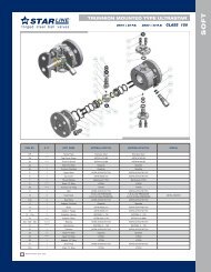
CVS Type <strong>128</strong><strong>PQC</strong> <strong>Control</strong> <strong>Valve</strong>: Fail-Closed with Cage-Style Metal Seatand Single TFE-V-Ring PackingCVS Design <strong>128</strong><strong>PQC</strong>Cageless Soft-Seat DetailFail-Open Actuator DetailFigure 5: Typical CVS <strong>Series</strong> <strong>128</strong><strong>PQC</strong> <strong>Control</strong> <strong>Valve</strong> Assembly9
Parts ListKey Description Part Number1 Upper Diaphragm Casing, Steel CVS24A8816X0122 Spring Plate, Zinc Plated Steel CVS14A8819X0123 Vent Assembly CVS1C8937000A24 Washer, Steel CVS1A7423289925 Indicator Bushing, 316 SST CVS13A2323X0126 Indicator Cover, Plastic CVS15A1580X0127 Travel Indicator Disc Nut, Plastic CVS1F7305069928 Machine Screw, SST CVS14A8818X0129 Indicator Fitting SST CVS15A0726X01210 O-Ring, Nitrile CVS1H29260699211 Spring, 302 SST CVS16A0431X01212 Main Spring, Cadmium Plated Steel See Table 213 Nameplate, Aluminum CVS24A7156X01214 Cap Screw, Plated Steel (2 req’d) CVS1E76032405215 Hex Nut, Cadmium Plated Steel (17 req’d) CVS1A34652412216 Locknut, Plated Steel CVS15A7591X01217 Lower Diaphragm Casing, Steel CVS24A8810X01218 O-Ring Retainer, Polyethylene CVS Type <strong>128</strong><strong>PQC</strong> CVS14A9053X01219 O-Ring, Nitrile CVS Type <strong>128</strong><strong>PQC</strong> CVS1P42070699220 O-Ring, Viton CVS Type <strong>128</strong><strong>PQC</strong> CVS1U84180638221 Spring CVS Type <strong>128</strong><strong>PQC</strong>17-7PH SSTCVS15A7584X012Inconel X750CVS15A1809X01222 O-Ring, Nitrile CVS Type <strong>128</strong><strong>PQC</strong> CVS11A8741X0121/4” (6.4 mm) CVS14A8823X022316 SST CVS Type <strong>128</strong><strong>PQC</strong> 3/8” (9.5 mm) CVS14A8805X0221/2” (12.7 mm) CVS14A7157X02223 Cage Austenitic SST w/1/4” (6.4 mm) CVS15A6800X012TungstenCVS Type <strong>128</strong><strong>PQC</strong>Carbide Seating3/8” (9.5 mm) CVS15A6801X012Surface24 Pipe Plug, Steel CVS1A79472899225<strong>Valve</strong> PlugMetal SeatCompositionSeat, AusteniticSST/polyethyleneCVS Type <strong>128</strong> <strong>PQC</strong>1” BodyCVS Type <strong>128</strong> <strong>PQC</strong>1” Body1/4” (6.4mm) and3/8” (9.5mm) port316 SST CVS16A2087X012Austenitic SST w/Tungsten CarbideSeating Surface1/2” (12.7mm) port1/4” (6.4 mm) through 1/2” (12.7 mm)portCVS15A6804X012316 SST CVS14A6618X012CVS15A3199X0123/4” port CVS15A3197X012<strong>Valve</strong> Plug Stem, 316 SST 1” Body, CVS Type <strong>128</strong><strong>PQC</strong> CVS14A8806X01226 <strong>Valve</strong> Body, Steel 1” NPT, CVS Type <strong>128</strong><strong>PQC</strong> CVS24A8802X01227 Packing Box Washer, SST1/2” (12.7 mm) or smaller port CVS14A6617X0123/4” (19.1 mm) port CVS14A8807X01228 Packing Box, SST CVS Type <strong>128</strong><strong>PQC</strong> CVS14A8809X01229 Washer, SST (2 req’d) CVS Type <strong>128</strong><strong>PQC</strong> CVS14A8808X012Complete SetCVS14A8812X01230Male AdaptorCVS1J227206242Packing Set, CVS TypeV-Ring (4 req’d)CVS1J255206992TFE<strong>128</strong><strong>PQC</strong> Individual PartsFemale AdaptorCVS1J233201012Wiper RingCVS1R2516X001231 O-Ring, Nitrile CVS13A1584X01233 Washer, Cadmium Plated Steel CVS14A9770X01234 Diaphragm Plate, Zinc Plated Steel CVS14A8814X01235 Diaphragm, Neoprene w/nitrile insert CVS14A8813X01237 Paper Tube ---38 Paper Label ---39 Protective Sleeve-Web ---40 Cage Puller CVS15A2525X012Keys 5, 7, 8, 9, 10, 11Complete AssemblyCVS35A1588X0A210
Notes:CVS <strong>Control</strong>s Ltd. strives for the highest levels of quality and accuracy. The information included in this publication is presented forinformational purposes only. CVS <strong>Control</strong>s Ltd. reserves the right to modify or change, and improve design, process, andspecifications without written notice. Under no circumstance is the information contained to be interpreted to be aguarantee/warranty with regard to our products or services, applicability or use.Selection, use and maintenance are the sole responsibility of the end user and purchaser. CVS <strong>Control</strong>s assumes no liability for theselection use and maintenance of any product.11
Head Office3900 – 101 StreetEdmonton, Alberta, Canada T6E 0A5Office: (780) 437-3055Fax: (780) 436-5461Calgary Sales Office205, 2323 – 32 Avenue NECalgary, Alberta, Canada T2E 6Z3Office: (403) 250-1416Fax: (403) 291-9487Website: www.cvs-controls.comE-Mail: info@cvs-controls.comGlobal Supply Line Sole Agents Australia, New Zealand & PNGwww.globalsupplyline.com.auRev 2, Mar 0912