Product Manual 128 PQC Series Control Valve 1" 1500 lbs
Product Manual 128 PQC Series Control Valve 1" 1500 lbs
Product Manual 128 PQC Series Control Valve 1" 1500 lbs
- No tags were found...

Create successful ePaper yourself
Turn your PDF publications into a flip-book with our unique Google optimized e-Paper software.
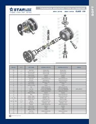
Replacing Packing and Trim continued,3. Accessible areas should be cleaned at thisstage, and all necessary maintenanceperformed. The actuator and attached trimparts can be turned over and held by thevalve body.4. To separate trim and access packing partsor seal O-rings, first loosen and remove thevalve plug (Key 25) and remove the packingbox washer (Key 27).5. Remove the packing box (Key 28), O-ringretainer (Key 18), stem O-ring (Key 19) anddiaphragm casing O-ring (Key 31) off thestem.6. Install replacement parts as necessary.6.1. If a complete packing and trimassembly is being installed, remove theassembly from the tube (Key 37),keeping the web sleeve (Key 39) on theassembly so the parts remain in place.Roll the sleeve back as necessaryduring installation.6.2. Continue pushing the assembly ontothe stem until the valve plug and cageare pushed away from the packing boxwasher or wiper ring. Roll the websleeve back into place just past thepacking box.6.3. If installing nitrile/cotton packing, thepacking rings may be lubricated withsilicon based product.7. Slide the packing box onto the stem until thepacking box, the O-ring (Key 19) and the O-ring retainer (Key 18) and the diaphragmcasing O-ring (Key 31) are sealed againstthe diaphragm casing.7.1. Ensuring proper positioning of the O-rings will prevent them from being cutwhen other parts are compressedagainst them.7.2. Advance the packing spring washer(Key 29) , packing spring (Key 21),second packing spring washer, wiperring and packing box washer (Key 27, ifincluded in the assembly) down ontothe stem.8. For installation of the packing and trimassembly, it is necessary to remove thesleeve, cage puller (Key 40) and cage (Key23) from the valve plug depending onindividual valve configuration.9. Fix the valve plug onto the stem, rotating theplug until the shoulder makes snug contactwith the stem. No further tightening isnecessary.10. To replace the cage or access the cage O-ring(Key 22), remove the cage from the body (Key26) using the cage puller or a wire hook.Replacement parts can be installed asnecessary.11. Attach the actuator and trim to the valve body(Key 26), paying special attention to the cageO-ring to prevent damage. Thread the fournuts (Key 32) to the lower diaphragm casingassembly screws. Nuts must be tightened to15-foot-pounds (20N• m).12. Reconnect the input signal tubing to theactuator connection of the appropriatediaphragm casing.Figure 3: Replacement Packing and TrimAssemblies for Metal SeatedConstructions5