MEFV Excess Flow .indd - Brass Craft
MEFV Excess Flow .indd - Brass Craft
MEFV Excess Flow .indd - Brass Craft

You also want an ePaper? Increase the reach of your titles
YUMPU automatically turns print PDFs into web optimized ePapers that Google loves.
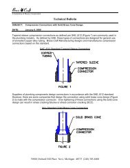
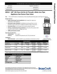
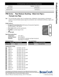
LIMITATIONS OF SAFETY+PLUS EXCESS FLOW VALVES:<strong>Excess</strong> <strong>Flow</strong> Valves provide a useful safety function in reducing the risk of catastrophic gasleaks in the event of a rupture in a low-pressure gas piping system. This brochure explainswhat protection excess flow valves offer, conditions that can interfere with that protection,and suggestions for effective EFV installation.AN EXCESS FLOW VALVE IS NOT DESIGNED TO CLOSE, THUS MAY NOT PROVIDE PROTECTION, IFANY OF THE FOLLOWING CONDITIONS ARE PRESENT:(1) The break to the downstream line is not large enough to allow an open-ended flow of gas toactivate valve closure.(2) An improperly sized gas utility meter does not produce enough gas flow upstream ofthe excess flow valve. The Safety+PLUS valve should not be installed unless the meteris replaced.(3) Foreign matter, such as pipe thread sealant, is lodged in the valve and prevents valve closure.(4) A manual shut-off valve downstream of Safety+PLUS valve is only partially open, preventingan open-ended flow of gas to activate valve closure.(5) The piping break or damage occurs upstream of the excess flow valve, preventing an openendedflow of gas through the valve.(6) The gas flow through the valve is in the wrong direction. <strong>Excess</strong> flow valve only respondsto gas flow in one direction (see product label). Arrow should point in the direction of gasflow (toward the sky).(7) The EFV has been damaged by fire, improper use or installation and is no longer in operatingcondition.! WARNING: If the excess flow valve has been damaged and is no longer in operating condition,the valve must be replaced.Safety+PLUS ®EXCESS FLOW VALVESfor Low Pressure Natural and LP(Propane) Gas SystemsCA-DSA03 01VALVE MATERIALS AND SPECIFICATIONS:Valve Body:Internal ValveComponents:<strong>Flow</strong> Label:4” length ASTM A53 galvanized steelor ASTM B43/B135 brass threaded pipe nippleAcetal PlasticVinyl w/ over laminateValve Size 3/4” I.P.S. 1” I.P.S.(Nominal O.D.): 1.050” 1.315”OperatingTemperature:-20° to 150° Fahrenheit! CAUTION: In outdoor installations where temperatures go below –20°F, fitting and surroundingpipe requires insulation or other device able to maintain temperature at valve above –20°F.QUALITY ASSURANCE:Safety+PLUS excess flow valves are 100% factory-tested at a minimum operating pressure of7” water column.APPLICATION:• Safety+PLUS excess flow valves are intended only for use with low pressure natural and LP(propane) gas systems.• Safety+PLUS valves are NOT intended for use with liquids.• Safety+PLUS valves are intended for installation immediately downstream of the gascompany meter & bypass tee outlet for complete gas piping protection. The Safety+PLUSvalve may also be used for large gas appliances, installed upstream of the appliance andits flexible gas connection.NOTE: Pool heaters and tankless water heaters MUST use a separate gas line and excess flowdevice as typical demand load exceeds 200 KBtu/Hr.• ! WARNING: Safety+PLUS valve must be tested once installed. Failure to test theproduct may conceal a faulty installation and product may not work as intended.Read “Installing the <strong>Excess</strong> <strong>Flow</strong> Valve” instructions for complete details.SIZING THE EXCESS FLOW VALVE TO YOUR INSTALLATION:(1) Add the maximum inputratings of all gas appliancesdownstream of the excessflow valve, fueled by the gaspiping system (referred as“total connected load”)*BTU ratings are hypothetical for the purposeof this example only.(2) Using Chart 1, select the Safety+PLUS valve whose “maximum customer demand load”is closest to the calculated “total connected load” of the household. NOTE: The calculated“total connected load” MUST NOT EXCEED the “maximum customer demand load” rating.! WARNING: DO NOT OVERSIZE the device for anticipated appliance additions.The excess flow valve MUST be sized according to the current “total connectedload”. Safety+PLUS is dependent on the given gas piping system’s ability to generatethe required excess gas flow.example: “total connected load” for household = 227,000 BTU/Hr**Calculated in above exampleModel #EP16-A 275,000EP16-B 375,000EP16-D 500,000example: water heater –range –dryer –furnace –gas log fireplacetotal connected loadMaximum CustomerDemand Load40,000 BTU/Hr*68,000 BTU/Hr*22,000 BTU/Hr*65,000 BTU/Hr*32,000 BTU/Hr*227,000 BTU/HrChoose thisSafety+PLUSValveDistributed By:39600 Orchard Hill PlaceNovi, Michigan 48375-5331TEL: 248-305-6000 FAX: 248-305-6011www.brasscraft.comManufacturer assumes no responsibility for failure due to improper installation.©2005 <strong>Brass</strong> <strong>Craft</strong> Novi, MI 48375-5331 U.S.A.All Rights Reserved. www.brasscraft.comManufactured in USA.Safety+PLUS® is a registered trademark of <strong>Brass</strong><strong>Craft</strong> Manufacturing.REV. 6/05➤ The next generation in gas safety products. The Safety+PLUS valve shuts off theprincipal flow of gas to your home in the event of a catastrophic break in your home’sgas piping system.➤ Responds to catastrophic ruptures in the home’s gas piping system much the waya master circuit breaker responds to overloads in the electrical system.➤ Easy to Install, maintenance-free protection 24 hours a day, 365 days a year.➤ Used for residential, commercial and institutional facilities with 7” w.c. to 2 psiginlet pressure! DANGER: Read ALL installation instructions and product limitationsprior to product installation.SAFETY+PLUS EXCESS FLOW VALVE INSTALLATION INSTRUCTIONS FOR LOWPRESSURE NATURAL AND LP (PROPANE) GAS SYSTEMS:• ! WARNING: This product shall only be installed by a qualified plumber registered to performwork on gas piping systems.• ! WARNING: This valve must be installed in compliance with local codes or, in the absence oflocal codes, with the National Fuel Gas Code, ANSI Z223.1 / NFPA 54, IAPMO-UniformPlumbing Code, or International Fuel Gas Code.• ! WARNING: The Safety+PLUS valve must be installed immediately downstream of thegas company meter and bypass tee outlet using standard pipe fittings and procedures.• Safety+PLUS valves may also be used with large capacity gas appliances, installedupstream from the appliance and its flexible gas connection.• ! WARNING: The excess flow valve must be installed within 5 degrees of the verticalposition with the flow arrows on the product label pointing in the direction of the gasflow (toward the sky). Read installation instructions (below) for complete details.INSTALLING THE EXCESS FLOW VALVE:! DANGER: Read All Installation Instructions and Limitations Before Installing(1) The excess flow valve should be examined before installation, or if removed for systemmaintenance, to ensure that all parts are in good condition and the internal float is able tomove freely without obstruction.(2) To begin installation, turn the handle of the main gas shut-off valve (Figure 1 - “A”) 90° toshut off gas supply. Gas supply is off when valve handle is perpendicular to the gas pipe.Turn off all gas appliances and close all manual gas shut-off valves at each appliance.! DANGER: ALL gas appliances, manual shut-off valves AND the main gas shut-off valveon meter MUST BE SHUT OFF BEFORE beginning excess flow valve installation! Appliancesor gas shut-off valves that are left on (open) during installation may release a potentiallyexplosive amount of gas resulting in personal injury including death in addition to possibledestruction of residence.
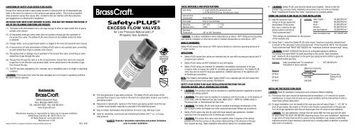
Figure 1Service RegulatorSet at 7-11" w.c.(A)Main GasShut-Off ValveLow Pressure Service7-11" w.c.(C)<strong>Excess</strong> <strong>Flow</strong> ValveTest Point(at Tee Connection)(B)Safety+PLUS<strong>Excess</strong> <strong>Flow</strong> ValveGas CompanyBy-Pass TeeGas MeterService intoDwelling(3) Using standard pipe fittings, install Safety+PLUS (Figure 1 - “B”) immediately downstreamof the gas company meter and bypass tee outlet, as close to the meter’s outlet as possible.It may be necessary to disconnect the gas meter outlet to install the excess flow valve.(4) The excess flow valve must be installed within 5 degrees of the vertical position with the flowarrows on the product label pointing in the direction of the gas flow (toward the sky).! WARNING: If the excess flow valve is not installed within 5 degrees of the vertical position,the valve will not operate properly, and will not respond to gas piping breaks.! WARNING: When using a thread sealant on male pipe threads, do not allow the sealant,thread tape, or debris to get inside the valve. Debris can lodge in the valve and prevent thevalve from operating properly.When Safety+PLUS valve is installed, check to be sure that:➤ Safety+PLUS is installed in the correct direction. The flow arrows on the productlabel should be pointing in the direction of the gas flow (toward the sky). In addition,the valve must be installed within 5 degrees of the vertical position.➤ The flow rate of the valve is correct for the installation. The ”total connected load”required for the establishment should be equal to or less than the “maximum customerde mand load” (BTU/Hr) of the valve (see Chart 1). Select the excess flow valve with the“maximum customer demand load” closest to the current “total connected load” withoutexceeding the “maximum customer demand load” of the valve.➤ Safety+PLUS valve is installed in the correct location, immediately downstream of thegas company meter and by-pass tee outlet. Preferably installed at the outlet of the gasmeter outside the foundation wall.(5) Once the EFV is installed, open main gas shut-off valve (Figure 1 – “A”) VERY SLOWLY topressurize system and initiate gas service to customer.! CAUTION: If gas enters system too quickly, the Safety+PLUS valve may close prematurely.If this occurs, follow step 8 to reset the valve.(6) TEST Safety+PLUS excess flow valve as follows:a) Make sure that the manual gas shut-off valve at each appliance is closed.b) Select a test point. This is the farthest possible point in the gas piping system that theEFV is intended to protect.! WARNING: For retrofit installations, the Safety+PLUS excess flow valve must be tested foreach branch of the gas piping system that the EFV is intended to protect. Follow steps “6c”and “6d” for each branch of the piping system.! WARNING: If test point is out of reach of main shut-off valve, two people must be used totest excess flow operation.c) Slowly remove the plug from the test point. Safety+PLUS should close when plug isfully removed. If not, valve size or installation is incorrect. Review sizing instructionsand steps 1 through 5 to determine that you have properly followed all instructions.d) Correct installation as necessary and repeat testing instructions. IF THE EXCESS FLOWVALVE STILL DOES NOT SHUT OFF WHEN THE TEST PLUG IS REMOVED, REMOVE THEDEVICE AND CALL CUSTOMER SERVICE.(7) Apply thread sealant to the male threads of pipe plug, replace and wrench tighten pipe plug.Check connection for gas leaks.(8) To RESET Safety+PLUS valve, close all downstream connections. Safety+PLUS valvewill pressurize the system and automatically reset itself. A soft “click” is heard whenSafety+PLUS valve resets. This may take up to 10 minutes.or RESET Safety+PLUS valve by closing the main shut-off valve (Figure 1 – “A”) to equalizethe pressure in the system. . A soft “click” is heard when Safety+PLUS valve resets.Re-open the main gas shut-off valve (Figure 1 – “A”) VERY SLOWLY to initiate gas serviceto customer REMINDER: If gas enters system too quickly, the Safety+PLUS valve willremain closed.(9) Once the Safety+PLUS valve resets, wait at least 10 minutes before reopening applianceshut-off valves. Take all necessary measure to be certain that all vapors have dissipated.Then open necessary appliance shut-off valves and re-light the appliance pilots asnecessary.! DANGER: DO NOT use motorized equipment or other sources of combustion to dissipategas vapors.! DANGER: Natural and LP (propane) gases are colorless, tasteless, and in their pure state,odorless vapors. They are odorized (awful smell of rotten eggs) so that their presence canbe detected. LP gases are heavier than air and dissipate slower than natural or manufactured gas. LP gas if released into the air will accumulate in low-lying areas such asbasements or crawl spaces.Chart 1Model #Inlet / OutletSizeMinimum InletPressureSizing Chart for Safety+PLUS <strong>Excess</strong> <strong>Flow</strong> ValvesMaximum InletPressureMaximumCustomerDemand LoadClosing <strong>Flow</strong>RateMaximumBy-Pass RateMaximum Equivalent Downstream Service Length (feet)3/4" Pipe 1" Pipe 1-1/4" PipeEP12-A 3/4" MIP 7" w.c. 2 psig 275 KBTU/Hr 300 KBTU/Hr 3 KBTU/Hr 60 190 771EP16-A 1" MIP 7" w.c. 2 psig 275 KBTU/Hr 300 KBTU/Hr 3 KBTU/Hr 60 190 771EP16-B 1" MIP 7" w.c. 2 psig 375 KBTU/Hr 400 KBTU/Hr 3 KBTU/Hr -- 125 200EP16-D 1" MIP 7" w.c. 2 psig 495 KBTU/Hr 600 KBTU/Hr 3 KBTU/Hr -- 46 144a) <strong>Flow</strong> rates given are for 0.6 Specific Gravity Natural Gas with an average heating value of 1000 BTU/cubic foot. Therefore, 1 KBTU/Hr is equal to 1 SCFH.b) Lengths calculated using Fritzsche low pressure equation.! DANGER: Make sure that all vapors have dissipated before lighting the pilot lights oroperating appliances.(10) Turn on all gas appliances one-by-one and operate all appliances (at maximum capacity)simultaneously to determine if the Safety+PLUS valve provides an adequate volume of gasto operate the appliances without closure. Larger excess flow valves are available for highervolume applications, if necessary.(11) If you have any questions, please call customer service at 1-248-305-6000.TO RESET SAFETY+PLUS AFTER A PIPE BREAK:(1) Close the main shut-off valve (Figure 1 – “A”) at the meter upstream from the Safety+PLUSexcess flow valve (Figure 1 – “B”).(2) Shut off all downstream appliances and close the manual gas shut-off valves located at eachof the gas appliances.(3) Repair damage to gas piping system downstream from the Safety+PLUS valve(Figure 1 – “B”).(4) Follow step 8 in the installation instructions above to reset the Safety+PLUS valve.CHART 1 NOTES:1. Chart to be used in accordance with local plumbing codes and with reference to IAPMO/ANSIUPC 1-2003 Table 12.7; NFPA 54/ANSI Z223.1 – National Fuel Gas Code Table 12.2 or IFGCCharts 402.4.2. Pipe lengths are estimates only. Actual tests should be performed to determine valve’sability to trip under precise conditions.3. Calculations based on maximum pressure drop across valve and maximum closing flow ofvalve at given inlet pressure. Calculations based on actual valve test data would result inlonger lengths of pipe.4. ! WARNING: Calculations are based on pressure loss through the valve and given length /diameter of piping only. Additional pressure loss (through tapping tees, fittings, regulatorsand other restrictions) may result in reducing “maximum downstream service length”calculations. Therefore, always test each branch of the gas piping system that the EFV isintended to protect to be certain the EFV will operate correctly in the event of a catastrophicgas line break.5. Calculations based on black pipe systems only. For other piping fabrications, contactcustomer service.! CAUTION: The excess flow valve is sized by the maximum customer demand load andclosing flow rate (see Chart 1), not just by pipe size. Several models are available in thesame diameter pipe. Piping downstream of the excess flow valve must never be of asmaller diameter, excluding the stubout piping (see Chart 2). The actual stubout MUSTNOT EXCEED one foot in length. In addition, the values in Chart 2 represent the equivalentservice length of a one-foot stubout. These values must be subtracted from the “maximumequivalent downstream service length” given in Chart 1.Chart 2Stubout Sizing Chart for Safety+PLUS <strong>Excess</strong> <strong>Flow</strong> ValvesService Pipe ➤ 3/4" Pipe 1" Pipe 1-1/4" PipeStubout ➤ 1/2" Pipe 3/4" Pipe 1/2" Pipe 3/4" Pipe 1/2" Pipe 3/4" PipeEP12-A 7 1 15 2 71 21EP16-A 7 1 15 2 71 21EP16-B - - 15 5 0 0EP16-D - - 16 6 24 0