Custom Rearend Worksheet - Chris Alston's Chassisworks
Custom Rearend Worksheet - Chris Alston's Chassisworks
Custom Rearend Worksheet - Chris Alston's Chassisworks
- No tags were found...
Create successful ePaper yourself
Turn your PDF publications into a flip-book with our unique Google optimized e-Paper software.
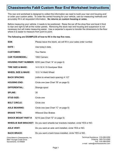
<strong>Chassisworks</strong> Fab9 <strong>Custom</strong> Rear End <strong>Worksheet</strong> InstructionsThis rear end worksheet is designed to collect the information we need to build your rear end housing and/or order your custom axles. To order the correct housing for your vehicle, use our measuring methods andaccurately fill in all requested information. No returns on custom housing or axles.Before measuring your vehicle, it needs to be positioned. Raise the car off the shop floor and level it frontto rear and right to left at the rocker panels. Removing the stock rear end housing and suspension is notnecessary but will make measuring easier. Use a carpenter’s square to transfer the dimensions to the floorwhere it is easier to measure from point to point.The following are EXAMPLES of how to fill in the top five rows.SO#:DATE :CUSTOMER:CAR YEAR/MODEL:Please leave this blank, we will fill in your sales order number.Use today’s date.Your Name1992 CamaroHOUSING PART NUMBER: 8250 (see Chart “A” on page 4)TIRE SIZE & MAKE:WHEEL SIZE & MAKE:14 X 32 X 15 Goodyear Slick15 X 14 Weld WheelBACK SPACING: (refers to wheel back spacing) 4 1/2”HOUSING END: Circle one (see Chart “B” on page 5)DIFFERENTIAL:Strange spoolSPLINE: 35STUD SIZE:BOLT CIRCLE:Circle oneCircle oneAXLE BEARING: Circle one (see Chart “C” on page 5)BRAKE TYPE:Wilwood Disc BrakesSHOCK MOUNT PART #: 6216 (see Chart “D” on page 5)WHEELIE BAR BRACKET: Do you want wheelie bar brackets installed, circle YES or NO.AXLE VENT:BACK BRACE:<strong>Chris</strong> Alston’s <strong>Chassisworks</strong>, Inc.8661 Younger Creek DriveSacramento, CA 95828Do you want an axle vent installed, circle YES or NO.Do you want a back brace installed, circle YES or NO.Technical Assistance: 916-388-0288Ordering: 800-722-2269Fax: 916-388-0295e-mail: sales@cachassisworks.comPage 1
The following are descriptions of the lettered blanks.“A” Width of the car from inside quarter panel lip to inside quarter panel lip.“B” Outside width of frame rails. NOTE: When using a <strong>Chassisworks</strong> Eliminator II chassis or rear frame kitthis is the outside width of the 4-link brackets.“C” Distance from wheel mounting surface to inside tire sidewall.“D” Overall width of tire mounted on the wheel from sidewall to sidewall.“E” Pinion offset is the relationship of the pinion centerline to the centerline of the chassis. Available offsets tothe passenger side are 0, 1/2”, 1”.“F” Axle flange offset is the distance from the housing end to the axle flange. Refer to Chart “B” on page 5.“G” Tire clearance from inside sidewall to frame rail. Should be 1” to 1-1/2” for a race car, or 1-1/2” to 2” for astreet car.“H” Wheel well width from frame rail to inner quarter panel lip.“I” Tire clearance from outside sidewall to quarter panel. Should be 1” to 1-1/2” for a race car, or 1-1/2” to 2”for a street car. Additional clearance may be required to remove the tires. Also, check the clearance at the topof the quarter panel and rear window.“J” This is the thickness of the disc brake hat or brake drum. Most steel brake drums are 1/8” thick. Mostaftermarket disc brake hats are 1/4” thick. Wilwood Early Big Ford hats are 1/2” thick.“K” Rear end width from axle flange to axle flange without disc brake hat or brake drum installed.“L” Rear end width from housing end to housing end. Available in 1/4 inch increments from 23” to 62”.“M” Width of the housing end can be found in Chart “B” on page 5. <strong>Chassisworks</strong> race style housing endswithout factory seal (Part nos. 8002, 8003, 8005, 8007, 8008) are 1” thick. Part no. 8004 and Strange floaterspindle are 1-1/8” thick. All ends with factory seal provision (Part nos. 8000, 8001, 8006) are 2” thick. Any otherhousing ends will need to be measured.“N” Length of passenger side axle tube from pinion centerline to end of tube, not including the housing end.“O” Length of driver side axle tube from pinion centerline to end of tube, not including the housing end.“P” Outside width of suspension brackets. For <strong>Chassisworks</strong> rear frame kits this will be the same as the“B” dimension. All other frames will need to be measured. Bracket widths are only available in 1/2 inchincrements from 17” to 42”.For <strong>Chassisworks</strong> billet canted 4-bar frame kits #7154, the “P” dimension will be the outside width of the lowercontrol arm brackets. This will always be the “B” dimension plus 1” for this frame.<strong>Chris</strong> Alston’s <strong>Chassisworks</strong>, Inc.8661 Younger Creek DriveSacramento, CA 95828Technical Assistance: 916-388-0288Ordering: 800-722-2269Fax: 916-388-0295e-mail: sales@cachassisworks.comPage 2
“T” Outside width of the lower shock mount brackets. For <strong>Chassisworks</strong> 2x3” or 1-5/8” rearframes and chassis kits this will be the “P” dimension minus 8-1/4”. For Eliminator II 4-linksuspensions this dimension is not necessary because the shock mount is part of the 4-link bracket.For <strong>Chassisworks</strong> billet canted 4-bar frame kit, the “T” dimension will be the inside width measured to the inneredge of the shock brackets. This will always be “B” dimension minus 10”.“U” Diameter of the axle pilot for your brake drum or disc brake rotor hat.Note: For housings with leaf spring mounting pads installed the two dimensions below “V” and “W”) will beneeded.“V” Center to center dimension of the leaf spring mounting pads.“W” Angle formed by the housing face and the bottom of the leaf spring mounting pad. Looking at thehousing from drivers side, an angle of less than 90 degrees indicates the front of the leaf spring pad is down.An angle greater than 90 degrees indicates the front of the leaf spring pad is up. Leaf spring mounting pad iswelded below the axle tube.CALCULATE THE REMAINING INFORMATION USING THESE FORMULAS.Symbol Key: + plus - minus × multiply ÷ divideAfter measuring the body for the “A” dimension, measure the tire for “C” and “D” dimensions. Decide howmuch tire clearance you need and enter “G” and “I” dimensions.1. Determine the “B” dimension by using this formula: A-(2×(D+G+I))=B2. Calculate for “H” using the formula: (A-B) ÷ 2=H.To double check the above, H-D should equal G+I. If all of these are correct, continue on. If not, go back andcheck all the above before going any further.3. Calculate the axle flange to flange “K” dimension using this formula: (2×C)+(2×G)+B-(2×J)=K4. Calculate “L” using the formula: K-(2×F)=L.Once you have determined the “L” dimension it must be rounded up or down to the nearest 1/4 inch. This slightchange in the overall rear end width is less than the decreased clearance caused by the tire side wall run out,this change will not cause a problem.5. The “F” dimension is determined by the type of housing ends used. Chart “B” shows some of the morecommon housing end dimensions. If you are using something other than the ones listed, you will need tomeasure for “F” using your stock rear end with the axle installed.6. Calculate “N” using the formula: (L÷2)-E-M=N7. Calculate “O” using the formula: (L÷2)+E-M=O If the pinion is centered, “N” and “O” will be equal.Your rear end worksheet should now be complete. Sign it and fax it to us at (916) 388-0295 or mail it to<strong>Chassisworks</strong> at 8661 Younger Creek Drive, Sacramento, CA 95828.If you have any additional questions, contact <strong>Chassisworks</strong>’ Technical Department at (916) 388-0288.<strong>Chris</strong> Alston’s <strong>Chassisworks</strong>, Inc.8661 Younger Creek DriveSacramento, CA 95828Technical Assistance: 916-388-0288Ordering: 800-722-2269Fax: 916-388-0295e-mail: sales@cachassisworks.comPage 3Rev 0805
Housing Part Number ChartChart “A”Part # Description8250 Fab9 Assembly no brackets, mild steel construction, 3” tubes8251 Fab9 Assembly no brackets, 4130 steel construction, 3” tubes8252Fab9 Assembly standard 4-link for spherical rod ends, 7/8” inside width with 3/4” holes, mild steelconstruction, 3” tubes8253Fab9 Assembly standard 4-link for spherical rod ends, 7/8” inside with 3/4” holes, 4130 steelconstruction, 3” tubes and 4130 brackets8254Fab9 Assembly standard 4-link for spherical rod ends, 7/8” inside with 3/4” holes, 4130 steelconstruction, 3-1/4” tubes and 4130 brackets8255Fab9 Assembly pro street 4-link for urethane rod ends, 1-5/8” inside width with 1/2” holes, mild steelconstruction, 3” tubes8256Fab9 Assembly pro street 4-link for urethane rod ends, 1-5/8” inside width with 1/2” holes, 4130 steelconstruction, 3” tubes and 4130 brackets8257 Fab9 Assembly standard ladder bars, 7/8” inside width with 1/2” holes, mild steel construction, 3” tubes8258Fab9 Assembly standard ladder bars, 7/8” inside width with 1/2” holes, 4130 steel construction, 3”tubes, and 4130 brackets8259Fab9 Assembly standard ladder bars, 7/8” inside width with 1/2” holes, 4130 steel construction, 3-1/4”tubes, and 4130 brackets8260 Fab9 Assembly pro street ladder bars, 1-1/4” inside width with 1/2” holes, mild steel construction, 3” tubes8261Fab9 Assembly Eliminator II 4-link for spherical rod ends, 7/8” inside width with 1/2” holes, includesintegral adjustable shock mount, mild steel construction, 3” tubes8262Fab9 Assembly Eliminator II 4-link for spherical rod ends, 7/8” inside width with 1/2” holes, includesintegral adjustable shock mount, 4130 steel construction, 3” tubes, and 4130 brackets8263Fab9 Assembly Avenger 4-link for spherical rod ends, 7/8” inside width with 1/2” holes, includesintegral adjustable shock mount, 4130 steel construction, 3-1/4” tubes, and 4130 brackets8264Fab9 Assembly pro street Eliminator II 4-link for urethane rod ends, 1-5/8” inside width with 1/2” holes,includes integral adjustable shock mount, mild steel construction, 3” tubes8265Fab9 Assembly pro street Eliminator II 4-link for urethane rod ends, 1-5/8” inside width with 1/2” holes,includes integral adjustable shock mount, 4130 steel construction, 3” tubes and 4130 brackets8266Fab9 Assembly with leaf spring pads (Chrysler style) 2-1/2” pad width and 1-7/32” hole, mild steelconstruction, 3” tubes8267Fab9 Assembly with leaf spring pads (Chrysler style) 2-1/2” pad width and 1-7/32” hole, 4130 steelconstruction, 3” tubes, and mild steel spring pads8268Fab9 Assembly with 4-bar and integral shock mount for urethane rod ends, 1-5/8” inside width with1/2” holes, mild steel construction, 3” tubes, mild steel brackets8269 Fab9 Assembly no brackets, 4130 steel construction, 3-1/4” tubes8270Fab9 Assembly billet aluminum parallel 4-link with swivel eyes, 2-1/8" inside width with 1/2" holesincludes adjustable shock mount, mild steel construction, 3" tubes8271Fab9 Assembly billet aluminum parallel 4-link with swivel eyes, 2-1/8" inside width with 1/2" holesincludes adjustable shock mount, 4130 steel construction, 3" tubes8272Fab9 Assembly billet canted 4-bar with swivel eyes, 2-1/8" inside width with 1/2" holes, includesadjustable shock mount, mild steel construction, 3" tubes8273Fab9 Assembly billet canted 4-bar with swivel eyes, 2-1/8" inside width with 1/2" holes, includesadjustable shock mount, 4130 steel construction, 3" tubesPage 4
Housing End ChartChart “B”Part # Housing End Type F Dimension M Dimension8000 Early Big Ford With Seal 2-3/8” 2”8001 Late Big Ford With Seal 2-1/2” 2”8002 Early Big Ford - Drag Race Style 2-3/8” 1”8003 Olds - Drag Race Style 2-3/4” 1”8004 Mopar/Dana - Drag Race Style 2-1/2” 1-1/8”8005 Small Ford - Drag Race Style 2-5/8” 1”8006 12-Bolt Chevy Style With Seal 2-3/4” 2”8007 Late Big Ford - Drag Race Style 2-1/2” 1”8008 Symmetrical 3” Lamb - Drag Race Style 2-3/4” 1”8009 Big GM - Seal Style For 3.150 Bearing 2-3/4” 2”8010 Ford 8.8 - Drag Race Style For 3.150 Bearing 2-1/2” 1”Strange Strange Floater Spindle, * J = 0 on Floater Spindle 4-1/2” 1-1/8”Axle Bearing ChartChart “C”Part # Bearing Description Bearing OD Bearing IDA1013 Timken Unit Axle Bearing With External Seal 3.150 1.562A1019 Race Axle Bearing With O-Ring 3.150 1.772A1021 Race Axle Bearing With O-Ring 3.150 1.562A1022 Race Mopar Axle Bearing (Non-Adjustable) 2.875 1.562A1023 Mustang Axle Bearing 2.835 1.562Shock Mount Part Number ChartChart “D”Part # Description6216 Adjustable Lower Coil Over Mount With Backbrace6224 Adjustable Lower Coil Over Mount No Backbrace6225 Adjustable Coil Spring Assembly With Backbrace6223 Adjustable Coil Spring Assembly No Backbrace6227 Eliminator II Straight Shock Mount6247 Eliminator II 6 Degree Shock Mount6281 Adjustable Lower Coil Over Mount For 4-Link Bracket Mount6284 Adjustable Coil Spring Assembly For 4-Link Bracket MountPage 5
CHRIS ALSTON'S<strong>Chassisworks</strong>THE HOME OF HIGHER TECHNOLOGY<strong>Custom</strong> Fab9 <strong>Worksheet</strong>S/O # DATE CUSTOMER CAR YEAR / MODELHOUSING PART NUMBER TIRE SIZE WHEEL SIZE BACK SPACINGHOUSING ENDS8000 8001 8002 8003 8004 8005 8006 8007 8008 8009 8010DIFFERENTIAL SPLINESTUD SIZEBOLT CIRCLEAXLE BEARING1/2" 5/8"5 on 4-1/2" 5 on 4-3/4" 5 on 5"A1013 A1019 A1021 A1022A1023BRAKE TYPE SHOCK MOUNT PART # WHEELIE BAR BRACKETS AXLE VENT BACK BRACEYES NO YES NO YES NOA B C D EF G H I JK L M N OP T U V WHFENDER LIPABB / 2GIFRAME CENTERLINE4 1/8"PTEFRAMEDCMFUJPASSENGER SIDEPINION CENTERLINEI HAVE PROVIDED THE ABOVE SPECIFICATIONS FORMY CUSTOM REAR END AND I ACCEPT FULLRESPONSIBILITY FOR THEM.NDRIVERS SIDESHOCK MOUNTOLKSIGNATURE REQUIREDPage 6Rev 0104


