SERVICE BULLETIN - Elbit Systems of America
SERVICE BULLETIN - Elbit Systems of America
SERVICE BULLETIN - Elbit Systems of America
Create successful ePaper yourself
Turn your PDF publications into a flip-book with our unique Google optimized e-Paper software.
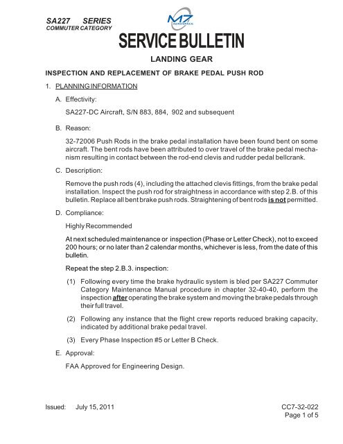
SA227SERIESCOMMUTER CATEGORYB. Inspection<strong>SERVICE</strong> <strong>BULLETIN</strong>(1) Determine which <strong>of</strong> the two clevis types are installed at the lower end. Theproduction (All aircraft listed in Step 1.A.) clevis is P/N MS27975-1. ServiceBulletin CC7-32-013, issued May 2002, required a replacement <strong>of</strong> this clevis withP/N YE-2 clevis. The two clevis types can be distinguished by their differentappearance and dimensions. Figure 2 illustrates the differences. The clevis at theupper end is also P/N MS27975-1 and does not get replaced. It can be used forcomparison to the lower clevis to confirm lower clevis type.(2) Inspect each push rod for bending. Observed occurances have typically beenrelatively sharp bends immediately above the lower clevis. Use a flat surface to rollthe rod to check for bending.(3) If the rod is bent, inspect the lower clevis for any damage associated with contactand interference. Damage may include cracking, gouging, and corrosion.C. Replacement/Installation(1) Replace any bents rods (replacement P/N 32-72006-009).(2) Replace lower clevis P/N MS27975-1 with clevis P/N YE-2 (if not previouslyaccomplished per Service Bulletin CC7-32-013).(3) If there are any contact indications (see Figure 2) on the YE-2 lower clevis (step2.B.(3)), replace the clevis if any following are true:(a) Indentations in the clevis are more than 0.050" deep.(b) Indentations have sharp internal features (rather than gently rounded).(c) The clevis is cracked.(4) Reassemble the push rod assemblies and install using previously removed clevispins (removed in step 2.A.(2)) and new cotter pins (P/N MS24665-132). Ensurelength <strong>of</strong> assembly matches previously installed rod end at each location. Alternatively,install brake push rod assemblies to dimensions shown in Figure 1.(5) Ensure that brake/rudder pedals have full freedom <strong>of</strong> movement. Clear anybinding as required.(6) Reinstall all items removed for access in step 2.A.(1).D. Restore aircraft to serviceable condition.E. Complete maintenance entry per 14 CFR 43.9.Issued: July 15, 2011 CC7-32-022Page 3 <strong>of</strong> 5
SA227SERIESCOMMUTER CATEGORY<strong>SERVICE</strong> <strong>BULLETIN</strong>F. Complete and return Service Bulletin compliance form to M7 Aerospace TechnicalPublications.Brake Pedal PushRod AssemblyRemove cotter pin andclevis pin top and bottomFIGURE 1Issued: July 15, 2011 CC7-32-022Page 4 <strong>of</strong> 5
SA227SERIESCOMMUTER CATEGORY<strong>SERVICE</strong> <strong>BULLETIN</strong>2.001.88YE-2 ClevisMS27975-1 ClevisInspect these locationsfor contact indicationsFIGURE 2Issued: July 15, 2011 CC7-32-022Page 5 <strong>of</strong> 5


