AN/PRC-117F(C) Multiband Multimission Radio Applications ...
AN/PRC-117F(C) Multiband Multimission Radio Applications ...
AN/PRC-117F(C) Multiband Multimission Radio Applications ...
- No tags were found...

Create successful ePaper yourself
Turn your PDF publications into a flip-book with our unique Google optimized e-Paper software.
17<strong>AN</strong>/<strong>PRC</strong>-<strong>117F</strong>(C) <strong>Multiband</strong> <strong>Radio</strong>High-Speed Data ModemSynchronous and Asynchronous high speed Trellis CodeModulation (TCM) provides 48/64 kbps data speed over Lineof-Sight(LOS) nets. The option supports still frame image orreal time video transmission and large file applications. Themodem can be used in conjunction with encryption, providingsecure high-speed data capability. The interface supportsMIL-STD 188-114A protocol using RS232E and RS422 levels.Situational Awareness (SA)The SA function of the radio can send and receive SA datawithin each transmission in most voice modes and a limitednumber of data modes. The Over the Air (OTA) format isfully compatible with the SINCGARS SIP SA format and canoperate with the ITT RT-1523E radio. This information is onlysent securely and cannot be sent as plain text to prevent sensitiveinformation intercept. Receiving radios can detect theSA information at the front of voice transmissions and willexport the information to an external device (PC) over theestablished PPP link. The data that is exported is fully compatiblewith C2PC systems and can be displayed using thisapplication.Optional FeaturesThese optional features must be ordered withnew <strong>AN</strong>/<strong>PRC</strong>-<strong>117F</strong>(C) radios. For software upgradesto existing radios, please refer to the Software Updatesection.10513-8141-01 Embedded IPThe Embedded Internet Protocol (IP) capability of the<strong>AN</strong>/<strong>PRC</strong>-<strong>117F</strong>(C) enables high-performance tactical IPnetworking over UHF tactical satellite communicationschannels and for Line-of-Sight communications throughsimple and flexible system configurations.10513-8142-01 Wireless CloningThis option provides radio-to-radio preset cloning of all110 radio nets over-the-air (OTA). No external cables areneeded. A unique user-defined TR<strong>AN</strong>SEC key andfrequency provide enhanced security by encrypting thedata sent over the air.Note: Only black data is clonedThe <strong>AN</strong>/<strong>PRC</strong>-<strong>117F</strong>(C) includes:■ R/T-1796(P) Manpack <strong>Radio</strong>■ Battery Box 10513-4800-02■ Manual 10515-0109-4100■ Quick Reference Guide 10515-0109-4000■ Handset 10075-1399■ VHF Blade Antenna 10012-0202■ VHF Blade Flexible Adapter A3140084-2■ VHF/UHF Flex Antenna 10369-0205■ Antenna Bag CW-503/<strong>PRC</strong>-25■ 6-foot KDU extension cable 10511-0704-12■ Data/Remote Cable 10513-0730-A2■ PPP/HPW Cable 10513-0710-A006■ RF-6760W-HPW Software on CD-ROM■ <strong>Radio</strong> Programming Application RF-6550M CD-ROM■ Remote Control Cable 10513-0740-A0064
17Software Upgrade Kits<strong>AN</strong>/<strong>PRC</strong>-<strong>117F</strong>(C) and VRC-103(V)Software Upgrade KitsExisting customers of the Advanced <strong>Multiband</strong><strong>Multimission</strong> Tactical <strong>Radio</strong> System can upgrade thefeatures in their fielded radios to the latest capabilities.All features are suitable for either the <strong>AN</strong>/<strong>PRC</strong>-<strong>117F</strong>(C)or the <strong>AN</strong>/VRC-103. Except as noted, these upgrades areprovided as software only and can be performed in anylocation where the proper tools can be used. The basicupgrade kit consists of a CD-ROM that contains theprogramming application wizard that guides the operatorthrough the process. Using the remote control cablesupplied with each radio and a Windows-compatiblepersonal computer, a radio can be upgraded in severalminutes. Please contact Harris for detailed informationregarding programming compatibility and radioconfigurations.10513-8121-01MIL-STD-188-181B UpgradeThe MIL-STD-188-181B software only upgrade providesthe latest high-speed SATCOM data capability for the<strong>AN</strong>/<strong>PRC</strong>-<strong>117F</strong>(C). All data rates in both 5 kHz and25 kHz UHF SATCOM channels are supported.10513-8122-01SINCGARS ESIP and Mode 2/3 Fill UpgradeThe SINCGARS ESIP upgrade provides additional datacapability for the <strong>AN</strong>/<strong>PRC</strong>-<strong>117F</strong>(C) in SINCGARS VHFfrequency operation, including full Tactical Internetcapability when used in conjunction with an externaldata device. Complete interoperability with SINCGARSESIP radios is assured. In addition, enhanced mode 2/3fill operation for combined COMSEC/TR<strong>AN</strong>SEC fill issupported. This upgrade requires hardware modificationsthat must be performed at Harris.10513-8123-01MIL-STD-188-182A and 183A DAMA Upgrade10513-8124-01Embedded IP UpgradeThe Embedded IP software upgrade can be used withradios that contain ICP software version 1.8 or later.The embedded Internet Protocol (IP) capability of the<strong>AN</strong>/<strong>PRC</strong>-<strong>117F</strong>(C) enables high-performance tacticalnetworking over UHF tactical SATCOM channels and forLine-of-Sight communications through simple andflexible system configurations. Embedment of the IPcapability into the <strong>AN</strong>/<strong>PRC</strong>-<strong>117F</strong>(C) radio providesunsurpassed performance, capitalizing on the existingHPW high-speed waveform technologies in the radioand eliminates the need for external front-end IPdevices. Because they both use the same channel accesstechnology, IP networks can share channels with HPWnetworks. The <strong>AN</strong>/<strong>PRC</strong>-<strong>117F</strong>(C) network parameters canbe configured through the radio front panel, viaremote control, or via the RPA.10513-8124-02Embedded IP with Hardware Upgrade<strong>AN</strong>/<strong>PRC</strong>-<strong>117F</strong>(C) radios that contain ICP software version1.73 or earlier require a hardware upgrade that mustbe performed at Harris to obtain the Embedded IP softwareupgrade. The embedded Internet Protocol (IP)capability of the <strong>AN</strong>/<strong>PRC</strong>-<strong>117F</strong>(C) enables high-performancetactical networking over UHF tactical SATCOMchannels and for Line-of-Sight communications throughsimple and flexible system configurations. Embedmentof the IP capability into the <strong>AN</strong>/<strong>PRC</strong>-<strong>117F</strong>(C) radio providesunsurpassed performance capitalizing on theexisting HPW high-speed waveform technologies in theradio and eliminates the need for external front-end IPdevices. Because they both use the same channel accesstechnology, IP networks can share channels with HPWnetworks. The <strong>AN</strong>/<strong>PRC</strong>-<strong>117F</strong>(C) network parameters canbe configured through the radio front panel, via remotecontrol, or via the RPA.The MIL-STD-188-182A and -183A software onlyupgrade provides the latest Demand Assigned MultipleAccess SATCOM capability for the <strong>AN</strong>/<strong>PRC</strong>-<strong>117F</strong>(C). Alldata rates in both 5 kHz and 25 kHz UHF SATCOMchannels are supported.6
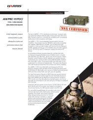
17Vehicular Adapter/AmplifiersVEHICULAR ADAPTER/AMPLIFIERS<strong>AN</strong>/VRC-103(V)1Vehicular Adapter/Power Amplifier<strong>AN</strong>/VRC-103(V)2Vehicular Adapter/Power Amplifier with VHF and UHFCollocation FilterThe <strong>AN</strong>/VRC-103(V)1 provides a vehicular mounting andpower amplification option for the <strong>AN</strong>/<strong>PRC</strong>-<strong>117F</strong>(C). Theamplifier provides a 50 watt output in FM mode from30 to 512 MHz, and 50 watts PEP in AM mode from 90to 512 MHz. Integrated into the amplifier is a hoppingcollocation filter for 30 to 90 MHz VHF and a SATCOMcollocation filter to provide enhance collocationperformance in demanding RF environments.The VRC-103 has four antenna parts. One is dedicated toSATCOM only, while the other three are frequencyprogrammable. The <strong>AN</strong>/VRC-103(V)1 operates from a 28VDC source. The <strong>AN</strong>/VRC-103(V)1 includes an <strong>AN</strong>/<strong>PRC</strong>-<strong>117F</strong>(C) radio, the AM-7588 power amplifier, a shockmount, operator’s guide, and cables to connect theradio to the amplifier. In addition, the necessaryaccessories to allow manpack operation using the<strong>AN</strong>/<strong>PRC</strong>-<strong>117F</strong>(C) as a jerk-and-run configuration areincluded. Interconnecting cables from the VRC-103(V)1 to the antenna or to the vehicle powersystem are not included.For connection to a vehicle power supply, use the10570-0720-01/-02 or the 12013-0716-A025 VehiclePower Cables. See the Accessories section.The <strong>AN</strong>/VRC-103(V)1 can be operated from an AC sourceusing the RF-5051PS-125C or a RF-5055PS Power Supplyand a 10570-0716-A006/-A025 cable. See theAccessories section.The <strong>AN</strong>/VRC-103(V)2 provides a vehicular mounting andpower amplification option for the <strong>AN</strong>/<strong>PRC</strong>-<strong>117F</strong>(C). Theamplifier provides a 50 watt output in FM mode from30 to 512 MHz, and 50 watts PEP in AM mode from 90to 512 MHz. Integrated into the amplifier is a hoppingcollocation filter for 30 to 90 MHz VHF, a SATCOMcollocation filter, and a UHF collocation filter to provideenhance collocation performance in demanding RFenvironments. The VRC-103 has four antenna parts. Oneis dedicated to SATCOM only, while the other three arefrequency programmable. The <strong>AN</strong>/VRC-103(V)2 operatesfrom a 28 VDC source. The <strong>AN</strong>/VRC-103(V)2 includes an<strong>AN</strong>/ <strong>PRC</strong>-<strong>117F</strong>(C) radio, the AM-7588A power amplifier,a shock mount, operator’s guide and cables to connectthe radio to the amplifier. In addition, the necessaryaccessories to allow manpack operation using the<strong>AN</strong>/<strong>PRC</strong>-<strong>117F</strong>(C) as a jerk-and-run configuration areincluded. Interconnecting cables from the VRC-103(V)2 to the antenna or to the vehicle powersystem are not included.For connection to a vehicle power supply, use the10570-0720-01/-02 or the 12013-0716-A025 VehiclePower Cables. See the Accessories section.The <strong>AN</strong>/VRC-103(V)2 can be operated from an AC sourceusing the RF-5051PS-125C or a RF-5055PS Power Supplyand a 10570-0716-A006/-A025 cable. See theAccessories section.7
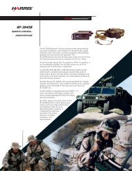
9System Interconnect<strong>AN</strong>/VRC-103 System Interconnect Diagram<strong>AN</strong>/VRC-103(V) System<strong>AN</strong>/VRC-103 (Front)J4CoaxJ7To Antenna(RF-390-ATXXX)CoaxTo SatelliteAntennaTo +28 VDC10570-0720-01Vehicle DC Power Cableor10570-0716-A006ToRF-5051PS-125C<strong>AN</strong>/VRC-103 (Rear)
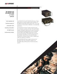
10Typical Configuration<strong>AN</strong>/VRC-103(V) System50 watt <strong>Multiband</strong> Vehicular System10181-5180-01Speaker10535-0707-A020Speaker Audio Cable10369-7211-25RF Cable Assy11080-3934-A015RF Cable AssyRF-390-AT003<strong>Multiband</strong> Whip Antenna10535-0706-A009Speaker Power Cable+28 VDC12005-0710-A29RF Cable AssyTo Vehicle Battery+28 VDC10570-0720-01Vehicle DC Power CableAM-7588 Power AmplifierPARTS LISTAM-7588Power Amplifier10570-0720-01 DC Power Cable10369-7211-25 RF Cable to RF-390RF-292Antenna MountRF-390-AT003<strong>Multiband</strong> Whip Antenna11080-3934-A015 RF-Cable to SOTM Antenna12006-9001-01 SATCOM Antenna (Bolt-on)10181-5180-01 Speaker10535-0707-A020 Speaker Audio Cable10535-0706-A009 Speaker Power Cable10511-0704-040 20 ft. KDU Extension Cable11080-6500-01 General Installation Kit11080-3900-11 SOTM Installation Kit12005-0710-A29 RF Cable Assy.12005-0710-B28 RF Cable Assy.10400-1136-A18 Ground Strap12005-1010-01 PA Adapter Unit12005-1920-01 AM-7588 Shock Tray Assembly12005-0710-B28RF Cable Assy.J2J3to Rear of<strong>AN</strong>/VRC-10312006-9001-01X-Wing SATCOM Antenna(Bolt on)or12006-9002-01X-Wing SATCOM Antenna(Magnet Mount)
11Typical ConfigurationTypical <strong>Multiband</strong> Vehicular SystemLine-of-Sight or SATCOM 20 watts<strong>AN</strong>/<strong>PRC</strong>-<strong>117F</strong>(C)<strong>Radio</strong> TransceiverRF-5851-AD001DC Mount AdapterRF-5870-VM001Mounting RackTo R/T J8Antenna Port20 ft. DC Power Cable12027-0205-A020To Adapter J1DC InputConnectorto Vehicle Power+28 VDCRF-5870-VM002Optional Mount Locking Kit(Not Shown)RF-390-AT00330-512 MHz<strong>Multiband</strong> Whip AntennaorX-Wing SATCOM Antenna12006-9001-01 (Bolt-on) or12006-9002-01 (Magnet Mount)11080-3934-A015 Coax CablePARTS LISTSATCOM<strong>AN</strong>/<strong>PRC</strong>-<strong>117F</strong>(C) <strong>Radio</strong> TransceiverRF-5851-AD001 12 VDC Adapter UnitRF-5870-VM001 Mounting RackRF-5870-VM002 Locking Mechanism12027-0205-A020 DC Power Cable 20 ft.PARTS LISTLine of Sight10369-7211-XXX Coaxial Cable (XXX = length in feet)11080-3934-A015 15 ft. Coax CableRF-390-AT003<strong>Multiband</strong> AntennaRF-292Antenna Mount12006-9001-01 X-Wing SAT Antenna (Bolt-on)12006-9002-01 X-Wing SAT Antenna (Magnet Mount)Note: For dual <strong>Multiband</strong> and SATCOM operation, manual switchingof J8 COAX cable is required.
17Antennasis usable up to 108 MHz. The system comes packaged ina canvas bag containing the antenna, a 3-foot mast, an80-foot coax cable with BNC connectors, ground stakes,a mounting base, guy assemblies, and a hammer.12006-9000-01High-Gain, Foldable SATCOM AntennaRF-291-AT001Tactical VHF High/UHF Omnidirectional Antenna,100 to 512 MHzThe RF-291 is an omni-directional transportable disconeantenna designed for use from 100 to 512 MHz,though it is usable up to 1,000 MHz. The 12-poundantenna is easily deployed on the sectional 8.5-m mast.Antenna, mast, guy-lines, a 15-m coax cable with BNCconnectors, and ground stakes all stow in a canvas bagfor transportability. The antenna is deployable in lessthan 15 minutes.SATCOM <strong>AN</strong>TENNASThis SATCOM antenna is a high gain, crossed yagiantenna for applications that require more gain in atactical package. This antenna provides +9.0 to 15 dBicgain with right hand polarization. The antenna weighs35 pounds. and can be broken down and transported inthe carrying bag provided.12006-9001-01X-WING SATCOM Antenna – Bolt MountRF-3080-AT001SATCOM Antenna - 240 to 400 MHzThe X-WING SATCOM antenna allows bolt on forpermanent installation onto vehicles, shelters and othermetal objects. The rugged design allows the antenna tobe used for SATCOM-On-The-Move (SOTM) operations.12006-9002-01X-WING SATCOM Antenna – Magnet MountThe antenna is a rapid deploy, high gain, crossed yagiantenna for SATCOM communications. It folds downto a compact 18.5 x 6 x 6 inch package and is 40 x 24 x24 inches when deployed. This antenna provides +7.0 to11 dBic gain with right hand polarization. The 3 dBbeamwidth is 85 in. The RF-3080-AT001 includes thecrossed dipole driven elements, a set of reflectors, twodirector extension kits, tripod, a coaxial cable with BNCconnectors, carrying case, and instructions. Deploymenttime is less than one minute.The X-WING SATCOM antenna has magnetic mountsallowing temporary installations onto vehicles, shelters,and other metal objects. The rugged design andmagnet mounts are strong enough to allow theantenna to be used for SATCOM-On-The-Move (SOTM)operations.13
17AntennasVEHICLE <strong>AN</strong>TENNASRF-387-AT001VHF Low-Band Whip Antenna 30 to 108 MHz –Center-FedRF-390-AT003RF-390-AT004RF-390-AT005RF-390-AT006Single Type N portCARC Green 383Single Type N portCARC TanSingle BNC portCARC Green 383Single BNC portCARC TanRF-392-AT001Tripod Mount for RF-390-AT00x AntennaThe RF-387-AT001 is a vehicular center-fed whipantenna with a flexible spring feed-through mountingbase. This antenna does not need a good ground plane.Length is 120-inches nominal whip height, 131-inchesincluding mounting base. The antenna mounts directlyto an RF-292 Mounting Base, which should be orderedseparately. RF connector is a BNC female connector onunderside of the base.RF-390-AT00xVHF/UHF Vehicular Whip Antenna 30 to 512 MHz –End-FedThe RF-390-AT00x multiband vehicular whip antenna isan end-fed vertical whip for use from 30 to 512 MHz.The exceptional bandwidth is obtained fromdistributive passive components along the antenna’slength. Antenna length is 110 inches. The RF-390-AT001has equivalent gain to other narrowband antennas. Thisantenna is the ideal choice for multiband radiosbecause it reduces the vertical signature by replacingthree antennas with a single antenna. The antennacomes with single or dual port to be compatible withboth its <strong>AN</strong>/<strong>PRC</strong>-<strong>117F</strong>(C) and the vehicular adapters. Thefeed-through spring base mounts directly to theRF-292 Universal Antenna Mount, which should beordered separately.The RF-390-AT00x antenna is available in differentcolors and different connectors:This tripod mount allows the use of the RF-390-AT00xVehicular Whip in a tactical application. The mountconsists of three legs and a center base for attachingthe RF-390 antenna. The three legs also act as a groundplane for the antenna. The tripod stands atapproximately seven feet and can be broken down andtransported in the carry bag provided. The RF-390Antenna is not included.RF-394VHF High-Band Vertical Antenna, 116 to 174 MHz –Center-FedThe RF-394 is a military-grade, center-fed, broadbanddipole antenna covering the 116 to 174 MHz frequencyrange (70 watts max). This 42-inch (1.1-m) antennainstalls on the standard mounting brackets found onmost military vehicles or ships or the RF-292 UniversalAntenna Mount, which should be ordered separately.The unit includes the antenna and its mountinghardware. RF connector is BNC female.RF-390-AT001RF-390-AT002Dual BNC portCARC Green 383Dual BNC portCARC Tan14
17AntennasRF-397UHF Vertical Antenna, 225 to 420 MHz – Center-FedThe RF-397 is a military-grade, center-fed, broadbanddipole antenna covering the 225 to 420 MHz frequencyrange (60 watts). This 33.5-inch (0.9-m) antenna andspring mount installs on the standard mountingbrackets found on most military vehicles or ships or theRF-292 Universal Antenna Mount, which should beordered separately. The unit includes the antenna andmounting hardware. RF connector is type N female.for vehicular mounting or the RF-1584 Antenna MastMount for mast mounting. The RF-292 and RF-1584mounts are ordered separately. RF connector isBNC female.<strong>AN</strong>TENNA ACCESSORIESRF-292Universal Antenna MountRF-398-01VHF Low-Band Vertical Antenna, 30 to 90 MHz – End-FedThe RF-292 is used to mount antennas to a vehicle,shelter, etc. Mounting hardware is included. Color:Olive Drab. Order the RF-292-01 for CARC Green 383,RF-292(S) for CARC Forest Green, RF-292(S)1 forCARC Tan.The RF-398-01 is a vertically polarized, end-fedmonopole antenna useable from 30 to 90 MHz (70watts max). The low profile, EMP protected, vehicularantenna is designed for installation where shortantenna length (75 inches) or low detectability isdesired. The feed-through spring mounts directly to anRF-292 Universal Antenna Mount, which should beordered separately. A tie-down is included. RFconnector is BNC female.RF-398-03VHF Low-Band Vertical Antenna, 30 to 108 MHz –Center-FedRF-1584Mounting Mast for Vehicular AntennasA rugged aluminum bracket for 1- to 2-inch diametermasts. Designed for mast-mounting antennas such asthe RF-387, RF-394, the RF-397, or the RF-398-02.Includes a mount and mast mounting hardware.10564-3070-01Diplexer AssemblyThe RF-398-03 is a center-fed dipole, vertically polarizedwhip antenna useable from 30 to 108 MHz (100 wattsmaximum). The EMP protected, broadband antenna isdesigned for permanent mounting on vehicles, shelters,towers, etc. The RF-398-03 does not require a goodground plane for optimum performance. Therefore, it isideal for tower or rooftop installations where goodground plane is not available. The unit consists of twofiberglass-radiating sections and a mount with a flexiblespring, and includes the antenna sections, a base, tiedownkit, and mounting hardware. The antennamounts directly to an RF-292 Universal Antenna MountThe 10564-3070-01 Diplexer Assembly combines the twoantenna ports on the <strong>AN</strong>/<strong>PRC</strong>-<strong>117F</strong>(C) manpack into asingle antenna port that covers the entire 30 to 512MHz frequency range. The antenna connection to theDiplexer is a BNC connector. The assembly is attachedto the <strong>AN</strong>/<strong>PRC</strong>-<strong>117F</strong>(C) by using the threads on one ofthe antenna connectors. Two short coax cables areincluded to connect the Diplexer Assembly to the<strong>AN</strong>/<strong>PRC</strong>-<strong>117F</strong>(C).15
17CablesDATA <strong>AN</strong>D REMOTE CABLES10511-0707-A006Generic Audio/Data Cable, Pigtail TerminationA generic Audio/Data Cable that is unterminated on theopposite end. Length is 6 feet.15013-0710-A006High-Performance Waveform (HPW) Cable – J3This cable is an asynchronous, PPP cable for use withthe HPW and IP functions on the <strong>AN</strong>/<strong>PRC</strong>-<strong>117F</strong>(C). Itconnects to the front panel J3 Data and a COM port ona computer using a 9-pin D style connector. Length is6 feet.10535-0780-A006Synchronous/Asynchronous Data Cable – J3This cable provides a synchronous or asynchronousRS-232 data interface to the radio. It can be used withHUITS over an <strong>AN</strong>/<strong>PRC</strong>-<strong>117F</strong>(C). The data terminalconnection end utilizes a 25-pin (DB-25) connector.Length is 6 feet.10513-0730-A1/-A2Data/Remote Control Cable – J3This cable provides both a synchronous/asynchronousdata interface and RS-232 remote control interface. Thisis a Y cable that connects to the front panel Dataconnector, J3. This cable can be used with the RF-6550F<strong>Radio</strong> Programming Application. Length of the 10513-0730-A1 is 6 feet, and the 10513-0730-A2 is 10 feet. One10513-0730-A2 is supplied with each <strong>AN</strong>/<strong>PRC</strong>-<strong>117F</strong>(C)manpack.10513-0740-A006Remote Control and Programming Cable – J6This cable provides both RS-232 remote control andprogramming interface to the radio via the front panelAccessory connector, J6. This cable can be used with theRF-6550F <strong>Radio</strong> Programming Application.Length is 6 feet.10513-0750-A006Remote Control and Programming Cable – J3This cable provides both RS-232 remote control andprogramming interface to the radio via the front panelData connector, J3. This cable can be used with theRF-6550F <strong>Radio</strong> Programming Application. Length is6 feet.10535-0760-A006Remote Control and Programming Cable – J9This cable provides both RS-232 remote control andprogramming interface to the radio via the rear panelconnector, J9. This cable can be used with the RF-6550F<strong>Radio</strong> Programming Application. Length is 6 feet.10518-1694-A006Data/Remote Control Y Cable for use withRF-5800R-RC200This cable provides both an synchronous/asynchronousdata interface and RS-232 remote control interface tothe RF-5800R when used with the <strong>AN</strong>/<strong>PRC</strong>-<strong>117F</strong>(C). Thisis a Y cable that connects to the front panel J3connector. The opposite end utilizes a 25-pin D styleconnector for data and a 9-pin D style connector forremote control. Length is 6 feet.NOTE: This cable can only be used on the RF-5800RRemote Control. It will not work connected directly tothe <strong>AN</strong>/<strong>PRC</strong>-<strong>117F</strong>(C) manpack. A 10518-1694-A006 cablecomes with each RF-5800R-RC200CLONING CABLES12013-0720-A006Clone Cable - J6Cable for cloning of one radio’s programming (preset,nets, etc.) to another radio using the J6 (Blue Dot) frontpanel connector. Length is 6 feet.10513-0700-A006Clone Cable - J9Cable for cloning of one radio’s programming (preset,nets, etc.) to another radio using the J9 rear panelconnector. Length is 6 feet.RETR<strong>AN</strong>S CABLES12005-0717-A012Retransmission CableInterconnects two <strong>AN</strong>/<strong>PRC</strong>-<strong>117F</strong>(C) radio units via J3Data Connector to provide retransmission capabilitywith 12 feet of separation.10511-0717-01Retransmission CableInterconnects two <strong>AN</strong>/<strong>PRC</strong>-<strong>117F</strong>(C) radio units via J3Data Connector to provide retransmission capabilitywith 50 feet of separation.16
17CablesVEHICLE POWER CABLES10570-0720-01/-02<strong>AN</strong>/VRC-103(V) to Vehicle DC Power Cable KitThis cable connects an <strong>AN</strong>/VRC-103(V) Vehicular Adapteror AM-7588/A Amplifier to a 28 VDC power source or 28VDC vehicle supply. Includes fuses, fuse holder, and splitbolts to connect to existing power cables from vehiclebattery. Length of the 10570-0720-01 is 21 feet and the10570-0720-02 is 35 feet.12013-0716-A025<strong>AN</strong>/VRC-103(V) to Vehicle DC Power CableThis cable connects an <strong>AN</strong>/VRC-103(V) Vehicular Adapteror AM-7588/A Amplifier to a 28 VDC power source or 28VDC vehicle supply. The cable has preinstalled fuseholder and lugs. Length is 25 feet.POWER SUPPLY CABLES10570-0716-A006/-A025<strong>AN</strong>/VRC-103(V) to Power Supply CableThis cable connects an <strong>AN</strong>/VRC-103(V) Vehicular Adapteror AM-7588/A Amplifier to a RF-5051PS-125C PowerSupply, RF-5055PS AC/DC Supply or the RF-5052PS 12/24VDC Converter. Length of the 10570-0716-A006 is 6 feetand the 10570-0716-A025 is 25 feet.10570-0717-A003/-A006/-A025<strong>AN</strong>/VRC-103(V) to RF-5056PS CableThis cable connects an <strong>AN</strong>/VRC-103(V) Vehicular Adapteror AM-7588/A Amplifier to a RF-5056PS 12/24 DC/DCConverter. Length of the 10570-0717-A003 is 3 feet, the10570-0717-A006 is 6 feet and the 10570-0717-A025 is25 feet.10181-9831-009AC Power Cable - RF-5051PS-125CThis cable connects the RF-5051PS-125C to a standardUS-style AC outlet. Length is 9 feet.12027-0205-A020DC Power Cable - RF-5851-AD001The cable connects the RF-5851-AD001 to DC power.Length is 20 feet.10373-0030DC Power Cable - RF-5056PSThis cable connects the RF-5056PS DC/DC Converter tothe vehicle DC power source. Opposite end isunterminated. Length is 15 feet.PLGR/DAGR and GPS CABLES12005-0730-A006PLGR/DAGR Interface CableInterface cable to connect a PLGR to the radio via thefront panel J2 Connector. Length is 6 feet.12005-0740-A009NMEA Interface CableInterface cable to connect a NMEA compatible GPSreceiver to the radio via the front panel J2 connector.GPS end is a 9-pin D style male connector. Length is9 feet.KDU EXTENSION CABLES10511-0704-012KDU Extension Cable – 6 feet10511-0704-150KDU Extension Cable – 75 feetThis cable allows the user to operate the KDU whenremoved from the front panel of the radio.H<strong>AN</strong>DSET EXTENSION CABLES11042-0104-A0xxHandset Extension CableThis cable extends the distance of the attached cord onthe handset. Specify length in feet (xxx = length).Available lengths are 12 foot (–A012), 15 foot (-A015) or33 feet (- A033).17
17CablesJ55-0155-515Backshell for the J22-0126-026 connector.M39012/20-0101Right-angle male BNC connectors used to interconnectthe <strong>AN</strong>/<strong>PRC</strong>-<strong>117F</strong>(C) J5 and J8 antenna connectors tothe J2 VHF and J3 UHF input connectors on the<strong>AN</strong>/VRC-103(V) or AM-7588. This connector can be usedwith RG-58 or RG-223 coax.M55181/1-03Mating connector for the J1 DC POWER connector onthe <strong>AN</strong>/VRC-103(V) or AM-7588.COAX ADAPTERSUG-201A/UBNC female to N male coax adapterUG-349A/VBNC male to N female coax adapter19
17AccessoriesBATTERIESRF-5058-CH0066-Bay Battery Charger/Conditioner10075-1345-01 (BB-590/U)Rechargeable Nickel-Cadmium BatteryThe 10075-1345-01 (BB-590/U) is a rechargeable nickelcadmiumbattery that works well up to 50°C.BB-390A/URechargeable Nickel Metal-Hydride BatteryThe BB-390A/U is a rechargeable, nickel-metal hydridebattery that provides about 60% more capacity than aBB-590/U. Not recommended for use above 60°C.BA-5590/UNon-Rechargeable, Disposable Lithium BatteryThe BB-5590/U provides approximately three times theoperation life of the BB-590/U Rechargeable Nickel-Cadmium Battery. The BA-5590/U cannot be recharged,and is recommended for use in high temperatureapplications when temperatures exceed 55°C.BB-2590/U TypeRechargeable Lithium Ion BatteryThe BB-2590-type battery is a very high capacity,rechargeable, Lithium Ion battery that provides up to300% the energy density and 250% of the capacity ofthe BB-590/U. It is the same physical size, but is about20% lighter than the BB-390 and BB-590 batteries. Thebattery has a built-in battery life indicator. Use with theRF-5058-CH002 or RF-5058-CH006 battery chargers.The RF-5058-CH00X Battery Charger/Conditioner familyincludes 2-bay and 6-bay versions that will charge andcondition BB-590/U NiCad, BB-390/U NiMH, andBB-2590/U Type Li Ion batteries. The charger units areidentical except for physical size and weight and thenumber of batteries that can be simultaneouslyhandled. A mixed combination of up to two (CH002unit) or six batteries (CH006 unit) of these types can besimultaneously charged and/or conditioned. Indicatorsare provided to display the charge or conditioningstatus of each battery. The charging and conditioningcycles are automatic and will shut off when chargingis completed or under faulty battery conditions.Typical charging times for fully discharged batteriesvary with battery capacity, temperature, and batteryage, but are typically 2.5 hours for BB-590, 4 hours forBB-390, and 6 hours for BB-2590 type batteries. TheCharger/Conditioner is packaged in a waterproof casefor transport and operation. The system operates on 95to 260 VACS, 47 to 440 Hz, or 12 to 36 VDC autoranging.An instruction manual and a detachable DC powercable with alligator clips are included. Also includes adetachable AC cable with US NEMA 5-15P male on oneend and IEC 60320 female on the other.RF-5059-CH002NiMH/NiCad Battery Charger/DischargerBATTERY CHARGERSRF-5058-CH0022-Bay Battery Charger/ConditionerThe RF-5059-CH002 is a quick-charger system for 10075-1345-01 (BB-590/U) and BB-390A/U batteries. It is poweredby AC (95 to 265 volt) or DC (10 to 36 volt) power.AC and DC Input Cables should be ordered separately:10488-1386-01 AC cable, US (8 ft)10488-1387-01 AC cable, Continental Europe (2.5 m)10488-1388-A008 AC cable, UK (8 ft)10488-1385-A005 DC cable, Alligator clip tocharger (5 ft)20
17AccessoriesPOWER SUPPLIESRF-5052PS12/24 VDC ConverterRF-5051PS-125CPower SupplyThe RF-5051PS-125C provides power for the<strong>AN</strong>/VRC-103(V) or AM-7588/A Amplifier in a basestation, shipboard, or transportable operation. DCoutput is 28 VDC nominal at 30 amps. Input is 15 or 230VAC, 47 to 400 Hz. Requires 10181-9831-009 AC PowerCable (included).RF-5055PSAC/DC Power SupplyThe converter provides 26.5 volts DC at 17 continuousamps and 20 amps peak from a 12 volt DC source. Itpermits the operation of the <strong>AN</strong>/VRC-103(V) orAM-7588/A Amplifier in vehicles with 12 volt electricalsystems. It is designed for mounting in enginecompartments or other harsh environments. Theconverter includes a 15-foot DC input fused cable.BATTERY ELIMINATOR/ DC POWERADAPTERRF-5850-PS001Battery Eliminator – <strong>AN</strong>/<strong>PRC</strong>-<strong>117F</strong>(C)The RF-5055PS provides power for the <strong>AN</strong>/VRC-103(V)or AM-7588 Amplifier in a low-profile package. Thepower supply accepts 115 or 230 VAC and supplies26.4 VDC at 18 amps. When used with the RF-5056PSDC/DC Converter, the RF-5055PS will supply power tothe auxiliary power input of the RF-5056PS to conservevehicular battery life when AC power is available. A9-foot AC power cable is included.RF-5056PSDC/DC ConverterThe Battery Eliminator is used in place of the batterybox to provide operation of the <strong>AN</strong>/<strong>PRC</strong>-<strong>117F</strong>(C) from85 to 270 VAC, 47 to 440 Hz, or 9 to 36 VDC. The powersupply contains a battery to permit radio operation forshort time periods without external power. The batteryis recharged when external power is reapplied. The unitis supplied with both a DC power cable and an ACpower cable with a US-style plug attached. It can beused with the RF-5870-VM001 Shock Mount in vehicleapplications.RF-5910-PS003Battery Eliminator – <strong>AN</strong>/<strong>PRC</strong>-<strong>117F</strong>(C)The RF-5056 DC/DC converter provides a regulated26.5 VDC at 20 amps peak when supplied with a12 VDC, 24 VDC or 28 VDC from a vehicle DC powersystem. In 150 watt systems, the duty cycle is restrictedto 20%. This DC/DC Converter will also accept anauxiliary power input from a RF-5055PS AC/DC PowerSupply: when power is present at the auxiliary input,the RF-5056 converter shuts down to conserve thevehicle’s battery life. The low-profile design allowsmounting under the RF-5055PS sharing the same shocktray. The RF-5056 will also mount on the RF-5071VSM-03Shock Mount for use in severe shock applications. Nocables or mating connectors are provided. Use the10373-0030 DC Power Cable for connection to thevehicle DC Power (order separately).The Battery Eliminator is used in place of the batterybox to provide operation of the <strong>AN</strong>/<strong>PRC</strong>-<strong>117F</strong>(C) from95 to 270 VAC at 47 to 440 Hz, and 11 to 36 VDC. TheBattery Eliminator contains a Li Ion battery to permitradio operation for short periods without externalpower. The battery is recharged when external power isreapplied. The unit is supplied with both a DC powercable and an AC power cable with a US-style plugattached. It cn be used with the RF-5870-VM001 ShockMount in vehicle applications.21
17AccessoriesRF-5850-PS002Battery Eliminator – RF-5800RREMOTE CONTROLRF-5800R-RC101Remote Control SystemThe RF-5850-PS002 Battery Eliminator is used in place ofthe battery box to provide operation of the RF-5800RRemote Control from 85 to 270 VA, 47 to 440 Hz, or 9 to36 VDC. The unit is supplied with both a DC powercable and an AC power cable with US-style plugattached.RF-5910-PS004Battery Eliminator – RF-5800RThe Battery Eliminator is used in place of the batterybox to provide operation of the RF-5800R RemoteControl from 95 to 270 VAC to 440 HZ, and 11 to 36VDC. The Battery Eliminator contains a lead acid battery(BB-490) to permit radio operation for short periodswithout external power. The battery is recharged whenexternal power is reapplied. The unit is supplied withboth a DC power cable and an AC power cable with aUS-style plug attached.The RF-5800R-RC101 provides full remote control ofthe <strong>AN</strong>/<strong>PRC</strong>-<strong>117F</strong>(C) up to a distance of 3.5 km overstandard field wire. Full remote control of transmitand receive audio, data and control (using the KeypadDisplay Unit) of the manpack is possible from theremote site. All functions controlled by the KDU areavailable from the Remote Control. The system supportsthe full range of data applications for the <strong>AN</strong>/<strong>PRC</strong>-<strong>117F</strong>(C) including the RF-6550M <strong>Radio</strong> ProgrammingApplication and the RF-6760W Wireless MessagingTerminal. See the RF-5800R-RC201 for use with HPW.The RF-5800R-RC101 includes a Local Control Unit(LCU), a Remote Control Unit (RCU), a handset, aninterconnect cable from the LCU to the manpack,manual, operator cards, and carrying bag.RF-5800R-RC111Remote Control System with High Speed InterfaceRF-5851-AD001DC Power AdapterThe DC Power Adapter is used in place of the batterybox to provide operation of the <strong>AN</strong>/<strong>PRC</strong>-<strong>117F</strong>(C) from22 to 32 VDC. The adapter provides protection fromovervoltage, undervoltage ripple, etc. and is designedto meet MIL-STD-1275. The 12027-0205-A020 (20 foot)DC Power Cable should be ordered separately. It can beused with the RF-5870-VM001 Shock Mount in vehicleapplications.The RF-5800R-RC111 provides full remote control ofthe <strong>AN</strong>/<strong>PRC</strong>-<strong>117F</strong>(C) up to a distance of 3.5 km overstandard field wire and also includes a RS-449 interface.Full remote control of transmit and receive audio, dataand control (using the Keypad Display Unit) of themanpack is possible form the remote site. All functionscontrolled by the KDU are available from the RemoteControl. The system supports the full range of dataapplications for the <strong>AN</strong>/<strong>PRC</strong>-<strong>117F</strong>(C) including the RF-6550M <strong>Radio</strong> Programming Application and the RF-6760W Wireless Messaging Terminal. See the RF-5800R-RC211 for use with HPW. The RF-5800R-RC111 includes aLocal Control Unit (LCU), a Remote Control Unit (RCU),two high speed interfaces with cables, a handset, and ainterconnect cable from the LCU to the manpack,manual, operator cards, and carrying bag.RF-5800R-RC201Remote Control System - HPWThis is the same as the RF-5800R-RC101 except itincludes cables that allow operation with HPW.22
17AccessoriesRF-5800R-RC211Remote Control System with High Speed Interface –HPWThis is the same as the RF-5800R-RC111 except itincludes cables that allow operation with HPW.RF-5982-SA001Amplifier Speaker12027-0050-075Short Distance Remoting KitThe short distance remoting kit allows remote audioand control of the <strong>AN</strong>/<strong>PRC</strong>-<strong>117F</strong>(C) up to a distance of75 feet. The 10181-5180-01 Amplified Speaker is usedfor audio and handset remoting. The kit includes threecables: a 10535-0707-075 for audio, a 10535- 0706-075for speaker power, and a 10511-0704-150 KDUextension cable. The speaker requires an external26 VDC power source.AMPLIFIED SPEAKERS10181-5180-01Tactical Amplifier SpeakerAmplifies the headset audio for vehicular and otherapplications. A handset can be connected to thespeaker as well. The speaker features individual handsetand volumes, plus muting of the speaker when thehandset is keyed. It requires external 26 VDC power.Two cables are required (ordered separately).1. Speaker power cables:10570-3572-A0xx*10570-3574-A0xx*10570-3577-A0xx*2. Audio cables:Speaker to RF-5910-PS003 orPS004 Battery Eliminator cableSpeaker to RF-5051PS-125CPower SupplySpeaker to RF-5850-PS001Battery Eliminator cable10570-3573-A0xx*Speaker to <strong>Radio</strong> cableAmplifies the headset audio output for vehicular andother applications. The speaker features dual 6-pinhandset/headset connectors, individual handset/headsetand speaker volume controls, individualhandset/headset and speaker power switches, and avehicular mounting bolt. It requires external 26 VDCpower. Two cables are required (ordered separately).1. Speaker power cables:* All these cables are available in 4 lenghts: -A006=6feet, -A010=10 feet, -A015=15 feet, and -A020=20 feet.10570-3500-22Tactical Amplifier Speaker10535-0706-A00910535-0706-A07510535-0708-A00910535-0708-A07511068-0018-A0092. Audio cable:9-foot speaker to4pin power connector75-foot speaker to4-pin power connector9-foot speaker tounterminated leads75-foot speaker tounterminated leads9-foot speaker toRF-5850-PS001 BatteryEliminatorThis speaker connects to the J3 Data Connector on the<strong>AN</strong>/<strong>PRC</strong>-<strong>117F</strong>(C). It is powered off the radio’s battery. Itcan be used with the <strong>AN</strong>/VRC-103(V) or AM-7588 /Aamplifiers. Speaker must be disconnected if the dataconnector is required for other use.10535-0707-A009Audio cable that connects tothe <strong>PRC</strong>-<strong>117F</strong>(C) audioconnector J1.23
17AccessoriesBACKPACKSHEADSETS10512-0465-01FALCON II Backpack Carrying BagRF-3020-HS001/HS002Lightweight HeadsetsDesigned for short duration, dismounted missions. ThisOlive Drab-colored bag has pouches for accessories,antennas, and two additional batteries. The bag hasholes in the top for deployment of the antennas, theKeypad Display Unit Extension Cable, the handset cable,and other accessory cables while the bag is closed.10530-0460-01Backpack Carrying BagThis Olive Drab-colored bag is heavily padded anddesigned for use in airborne jump applications. It hasHERCULON reinforced areas and adjustable web to setthe carrying depth of the radio. It has room to storecables and two spare batteries. It is designed to fitinside a larger ALICE rucksack.H<strong>AN</strong>DSETSThe RF-3020-HS001 headset is a lightweight tacticalheadset with a single earphone, a gooseneck boommountedmicrophone, and a push-to-talk switch with aclothing clip for attachment. The RF-3020-HS002(shown) is identical to the RF-3020-HS001, but has asecond, silent push-to-talk button in sniper switchfashion. The headsets are rugged, submersible, anddesigned to meet tactical environmental requirements.HUB BATTERYB41-0010-004Hold Up Battery (HUB)Replacement Hold Up Battery for the <strong>AN</strong>/<strong>PRC</strong>-<strong>117F</strong>(C)radio. NSN 6135-01-525-9943KDU WRIST STRAP10075-1399Lightweight Handset - H-250/U (modified)RF-5931-CA001 (10512-0470-01)KDU PouchThe 10075-1399 is a high-grade, lightweight MILhandset for use with the FALCON II tactical radiosystems. One handset is supplied with each radio.This assembly provides a method to mount theremovable Keypad Display Unit (KDU) from the radio tothe left or right forearm using adjustable Velcrofasteners for size adjustment.24
17AccessoriesSOFTWARE APPLICATIONSRF-6550M<strong>Radio</strong> Programming Application (RPA)software runs on PCs and Pocket PC-based PDAs.Requires IP option in <strong>AN</strong>/<strong>PRC</strong>-<strong>117F</strong>(C) Manpack.SHOCK MOUNTSRF-5870-VM001Adjustable Shock MountThis software application allows the user to enterfrequency, mode, and other parameters into aWindows-based computer program and save it to a file.The program also downloads the operating parameterinto a radio using a 10513-0740-A006 AsynchronousData (PPP) cable. The computer file can program all theradios in a network. The RF-6550M RPA and 10513-0740-A006 cables are provided with each<strong>AN</strong>/<strong>PRC</strong>-<strong>117F</strong>(C) manpack.This shock mount allows installation of the<strong>AN</strong>/<strong>PRC</strong>-<strong>117F</strong>(C) Manpack into vehicular, shelter, orother applications that require shock isolation. Themount adjusts to allow the battery box, theRF-5850-PS001, or the RF-5851-AD001 to be used withthe manpack.RF-6760WWireless Message Terminal SoftwareRF-5870-VM002Security LockThis kit attaches to the RF-5870-VM001 to preventunauthorized removal of the radio from the shockmount. The kit requires the use of a padlock, which isnot included.When installed on a Harris-supplied or customersuppliedcomputer, the RF-6760W Wireless MessagingTerminal (WMT) software provides a transparentdelivery of e-mails, images and files over VHF or UHF.Operating like a standard PC with e-mail, the RF-6760Wallows the use of a SMTP/POP3 compliant e-mail client,such as Microsoft ® Outlook or Outlook Express. The RF-6760W can also be connected to an Ethernet TCP/IP areanetwork and can operate as a wireless messaginggateway. The package includes Harris Imager, a digitalimaging application.RF-6705Tactical IP ChatThis software application allows the user to exchangetext messages and files among field and networkeddata terminals. It uses either ARQ or broadcast datatransfer among members of an IP subnetwork. TheRF-5071VSM-03Shock Mount – RF-5051PS-125CThis shock mount allows installation of theRF-5051PS-125C Power Supply into vehicular, shelter orother applications that require shock isolation.12005-1920-01Shock Mount for <strong>AN</strong>/VRC-103(V)/AM-7588/AThis shock mount allows installation of the <strong>AN</strong>/VRC-103(V) Vehicular Adapter or AM-7588/A PowerAmplifier into vehicular, shelter, or other applicationsthat require shock isolation.Note: this mount is supplied with each <strong>AN</strong>/VRC-103(V)or AM-7588/A.25
17AccessoriesMOUNTS10564-6045-02Rack Mount KitThis Rack Mount Kit allows installation of the<strong>AN</strong>/<strong>PRC</strong>-<strong>117F</strong>(C) radio into a standard 19-inch wide x24-inch deep rack. The kit consists of a metal shelf andhardware for installation into the rack. It also includesa RF-5870-VM001 Shock Mount to mount the<strong>AN</strong>/<strong>PRC</strong>-<strong>117F</strong>(C) manpack on the metal shelf. Wheninstalled, the shelf and radio are stationary and do notextend on rack slides.11071-0900-04KDU Gimbaled MountThe 11071-0900-04 KDU Gimbaled Mount is used forremote mounting of the Keypad Display Unit (KDU)from the <strong>AN</strong>/<strong>PRC</strong>-<strong>117F</strong>(C). The mount can be used invehicles or on a desktop. The KDU is easily unlatchedfrom the radio and latched to the Gimbaled Mount forinstallation. It is just as easily reattached to the radio forjerk-and-run operation. The Gimbaled Mount can beused with the 10511-0704-012 6-foot KDU ExtensionCable. Three 10-32 x 0.75 inch hex mounting bolts, withwashers and locking nuts, and five black cable ties areincluded to facilitate installation. KDU and cables arenot included.10564-2400-01Manpack Transit Case – with Remote Speaker/KDUMountThis transit case provides an easily transportable, watertightcase for the <strong>AN</strong>/<strong>PRC</strong>-<strong>117F</strong>(C) manpack and itsaccessories. It includes a RF-5870-VM001 Shock Tray formounting the manpack and the standard battery box.The tray also accommodates the RF-5851-AD001 DCFilter or the RF-5850-PS001 Battery Eliminator, whichare purchased separately. An accessory bag is attachedto the back cover to hold the antennas, cables, andhandset. The <strong>AN</strong>/<strong>PRC</strong>-<strong>117F</strong>(C) is not included and mustbe purchased separately.A removable mount holds the 10181-5180-01 Speaker,the KDU, and a handset bracket allowing the radio tobe operated remotely from a distance up to nine feetaway. The 10181-5180-01 Speaker is not included andmust be purchased separately. Three cables arerequired, which must be purchased separately:1. 10535-0707-A009 9-foot audio2. 10511-0704-020 10-foot KDU extension cable3. 11068-0018-A009 9-foot DC power cable if usingthe RF-5850-PS001or10535-0708-A009 9-foot DC power cablewith unterminated leads26
17Accessories10564-2400-02Manpack Transit CaseThis transit case provides an easily transportable, watertightcase for the <strong>AN</strong>/<strong>PRC</strong>-<strong>117F</strong>(C) manpack and itsaccessories. It includes a RF-5870-VM001 shock tray formounting the manpack and the standard battery box.The tray also accommodates the RF-5851-AD001 DCFilter or the RF-5850-PS001 Battery Eliminator, whichare purchased separately. An accessory bag is attachedto the back cover to hold the antennas, cables, andhandset. The <strong>AN</strong>/<strong>PRC</strong>-<strong>117F</strong>(C) is not included and mustbe purchased separately.10564-3460-01Amplifier Transit CaseThis transit case provides an easily transportable, watertightcase for the <strong>AN</strong>/VRC-103(V) system. It consists oftwo transit cases, the 10564-3440-01 which houses theamplifier, and the 10564-3450-01 which houses theRF5051PS-125C Power Supply and the RF-5982-SA001Amplified Speaker. The amplifier and power supply aremounted on shock trays. A 10570-0716-A006 DC powercable (6 foot) that connects the amplifier to the powersupply is included. A 10570-3573-A006 (6 foot) cable toconnect the speaker to the radio, and a 10570-3574-A006 (6 foot) cable to connect the speaker to the powersupply are also included. The <strong>AN</strong>/VRC-103(V), <strong>AN</strong>/<strong>PRC</strong>-<strong>117F</strong>(C), RF-5051PS-125C and RF-5982-SA001 are notincluded and must be purchased separately.INSTALLATION KITS11080-6500-01<strong>AN</strong>/VRC-103(V)/AM-7558/A Installation KitThis kit contains the mounting hardware necessary tomount a <strong>AN</strong>/VRC-103(V) and RF-292 antenna mountinto a HMMWV. Kit includes bolts, nuts, grommets, etc.It does not include the amplifier shock tray, RF-292mount or any other metal work.27
17GlossaryADF – Audio/Data/Fill. KDU display item referring to theJ1 port on the front of the radio. This is an auto-sensingport that automatically configures the radio for voice ordata depending on what is connected (i.e., a handset ordata device).<strong>AN</strong>DVT – Advanced Narrowband Digital Voice Terminal.A COMSEC mode used in 5 kHz Narrowband SATCOMand DAMA. Compatible with the KY-99, KY-99A, andKY-100 COMSEC encryption devices.HPW – High-Performance Waveform. Satellitewaveform that can be used on both wideband andnarrowband UHF satellites. HPW offers high speed,reliable, error- free delivery of data.HUB – Hold Up Battery. 3.6 VDC commercially availablelithium battery (SAFT P/N LS14250, Tadiran P/N TL-2150,Harris P/N B41-0010-003, NSN 6135-01-435-4921; sizeAA). It is recommended to replace the HUB annually.HUB voltage level can be tested by conducting a BIT.COMSEC – Communications Security.CTCSS or CDCSS – Continuous Tone (Digital) CodedSquelch Subsystem. Sub-audible tones used to preventor deny access into LMR repeaters and handheld radios(i.e., FRS radios).DAMA – Demand Assigned Multiple Access. SATCOMcommunications mode of operation that uses a TDMAliketechnique to provide time-shared SATCOMchannels.dBw – Decibel. Unit used to measure RF signal strengthwith reference to 1 watt. (i.e., 1 watt = 0 dB).ECCM – Electronic Counter/Counter Measures. Refers tofrequency hopping capabilities (i.e., SINCGARS andHAVEQUICK I/II).ESIP – Enhanced SINCGARS Improvement Program.Added additional data capabilities to the existingSINCGARS mode. Features available for 30 – 87.975 MHzLOS and SINCGARS frequency hopping.FASCINATOR – Type-1 COMSEC mode used by someMotorola SABER II handheld radios.GPS – Global Positioning System. Satellite system that isused to obtain positioning and time information.Typically used with the radio to load TOD for frequencyhopping or HPW.HALF-DUPLEX – Refers to presets that use differentfrequencies for transmit and receive (i.e., SATCOM).HAVEQUICK – A frequency hopping mode used by theUS Air Force in the UHF range.INFOSEC – Information Security. This refers to the circuitboard in the radio that performs all crypto-related tasks.INC – Internet Controller. Equipment that providesSINCGARS capable radios an interface to battlefield IPconnectivity; acts as a router to gain access to theTactical Internet (TI) to use applications like FBCB2.IP – Internet Protocol. The <strong>AN</strong>/<strong>PRC</strong>-<strong>117F</strong>(C) supports TCPand UDP transport protocols.KDU – Keypad Display Unit. Removable radio interfacecontrol unit.KG-84 – COMSEC mode used for data traffic (i.e., HPW,TCM).KYV-5 – COMSEC mode used for SINCGARS ESIP EDMdata traffic.LOS – Line-Of-Sight. LOS refers to fixed frequency(simplex) presets.MELP – Mixed-Excitation Linear Predictive coding. Voiceencoding technique used for narrowband SATCOM andHF communications.MIL-STD – Military Standard.MIL-STD-188-181B – The Military Standard thatdescribes non-DAMA SATCOM, including the CPM datacapabilities. Referred to as MS181 in the radio (asopposed to HPW).MIL-STD-188-182A – The Military Standard thatdescribes 5 kHz DAMA SATCOM.28
17GlossaryMIL-STD-188-183A – The Military Standard thatdescribes 25 kHz DAMA SATCOM.TCM – Trellis Code Modulation. Technique used for highspeed LOS data operations (48 and 64 kbps).MIL-STD-188-184 – The Military Standard that describesa data protocol to be used over non-DAMA SATCOM(typically used by Viasat® Data Controllers such as theVDC-400).NMEA – National Marine Electronics Association 0183Interface Standard. Defines the interface to connect toa commercial GPS device (i.e., Garmin 12 Series).OTAR – Over The Air Rekey. Used to transmit/receiveCOMSEC variables from one radio to another.PLGR – Precision Lightweight GPS Receiver. Anothername for the <strong>AN</strong>/PSN-11, which is the GPS device usedby DoD.PPP – Point-To-Point Protocol. An industry standardprotocol that provides a method for transmittingdatagrams (IP traffic – TCP/IP and UDP) over serial pointto-pointlinks.TR<strong>AN</strong>SEC – Transmission Security.Type-1 – NSA-approved encryption algorithms used bythe DoD, capable of handling classified information.UHF – Ultra High Frequency. 225 MHz to 512 MHz in the<strong>AN</strong>/<strong>PRC</strong>-<strong>117F</strong>(C).VAU – Vehicular Adapter Unit (i.e., <strong>AN</strong>/VRC-103).VHF-HI – Very High Frequency – High Range. 90 MHz to225 MHz in the <strong>AN</strong>/<strong>PRC</strong>-<strong>117F</strong>(C).VHF-LO – Very High Frequency – Low Range. 30 MHz to90 MHz in the <strong>AN</strong>/<strong>PRC</strong>-<strong>117F</strong>(C).WMT – Wireless Messaging Terminal. Refers to thesoftware application RF-6760W, which is used alongwith Microsoft® Outlook for HPW messaging.RS-232 – Data protocol for unbalanced data interfaces.RS-422 – Data protocol for balanced data interfaces.SA – Situational Awareness. Mode used to send andreceive positional information.SARK – Saville Automatic ReKey. Another name forOTAR.SAT – Satellite.SATCOM – Satellite Communications.SIMPLEX – Refers to presets that use the samefrequency for both transmit and receive.SINCGARS – Single Channel Ground and Airborne <strong>Radio</strong>System. VHF-Low ground-to-ground frequency hoppingmode used by the U.S. Army.TACSAT – Tactical Satellite.29
Notes30
assuredcommunications ®RF Communications Division | 1680 University Avenue | Rochester, NY USA 14610 | Telephone 585-244-5830| www.harris.com | 1-800-4-HARRIS ext. 3515© Copyright 2007 Harris Corporation 5/07 AP2005-2A