High Speed Digital - SMTA
High Speed Digital - SMTA
High Speed Digital - SMTA

Create successful ePaper yourself
Turn your PDF publications into a flip-book with our unique Google optimized e-Paper software.
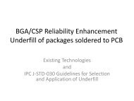
Market SegmentationIPInfrastructureComputingTest &Measurement<strong>High</strong> ReliabilityMobile Infrastructureupgrades, data center buildouts,and mobile appsdriving demand in NetworkInfrastructure expansionDemand for IntelArchitecture based serversdriving market, growth inUnix and Mainframe serversdown
PRODUCT REQUIREMENTS
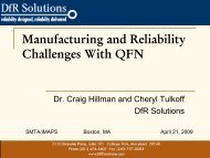
Relative PriceMid-Loss Lead-Free AssemblyEutectic 220°C Mixed Mode 245°C 260°C Lead-FreeComp #3 w/Low Dk GlassComp #4Comp #3Comp #2Theta(MCL-HE-679G)LegacyModifiedEpoxy0.78 mmWall-to Wall Space≤ 0.48 mmWall-to-Wall Space
Relative PriceMid-Loss CAF ResistanceGeneration 1 Generation 2 Generation 3Comp #3 w/Low Dk GlassComp #4Comp #3Comp #2Theta(MCL-HE-679G)LegacyModifiedEpoxy0.94 mmWall-to Wall Space0.78 mmWall-to Wall Space≤ 0.48 mmWall-to-Wall Space
Product Line PropertiesMid Loss Low Loss Ultra-Low LossPropertiesUnitsTheta(MCL-HE-679G)(MCL-FX-2)Under DevelopmentMaterial Type Halogen-Free Mid-Loss Low LossUltra LowLoss LamUltra LowLoss Bond PlyDk @ 1GHz 3.90 – 4.10 3.30 - 3.40 3.02 2.94Df @ 1GHz 0.008 – 0.010 0.002 - 0.003 0.0016 0.003Tg (TMA) °C 180 – 190 175 – 185 - 170Tg (DMA) °C 210 – 220 210 - 220CTE Z (< Tg) ppm/°C 35 - 45 48 - 55 58 50CTE Z (> Tg) ppm/°C 190 – 220 80 – 130UL Flammability UL-94 V-0 V-0 V-0 -IPC4101C Slash Sheet /127, /128/, /130 /102
Performance by Product LineMid Loss Low Loss Ultra-Low LossPerformMetricDescriptionTheta(MCL-HE-679G)MCL-FX-2Under DevelopmentHalogen-Free Mid-LossLow LossUltra Low LossLaminateBond-plyLow lossLead-FreeAssemblyCAF(Server)CAF(NetworkInfrastructure)InterconnectStress Test (IST) 2J-STD-020D(6x260°C)Precon:6x260°C15V, 600hr65°C/85%RHPrecon:6x260°C100V, 1000hr65°C/85%RH3.2mm, 18LPrecon:6x260°C10x +10x +0.48mm 1 Min - 0.48mm 1 - -600hr +600hr +Min - 0.48mm 1 Min - 0.48mm 1 - -In ProcessMin - 0.40mm 11000 Cycles(20°C – 150°C)In ProcessMin - 0.40mm 1In ProcessMin - 0.40mm 1In ProcessMin - 0.40mm 1HDI (1+n+1), 18L,Interconnect(IST) 3 Precon: 6x260°CStress Test2.l6mm<strong>High</strong>lyAcceleratedThermal Shock(HATS)HDI (3+n+3)12L, 1.65mmPrecon: 6x260°C1000 Cycles +(20°C – 150°C)100 Cycles(20°C -190°C)>500 Cycles(-40°C to +150°C)TBD
Product Line PropertiesMid Loss Low Loss Ultra-Low LossPropertyUnitsTheta(MCL-HE-679G)MCL-FX-2Under DevelopmentMaterial Type Halogen-Free Mid-Loss Low LossUltra Low LossLaminateUltra LowLoss BPAvailable CuTypeSTD, VLPSTD, VLP,Profile FreeRolled AnnealedElectrodeposited,Resistive Foils-Available CuThicknessmicrons 12, 18, 35, 70,105,140 12,18,35,70,105 18, 35 -Glass Types1037,1078,1080,3313,2116, 1501,76291037, 1078,1080,3313,21163313, 2116 unreinforcedSpread GlassTypes 1037, 1078, 3313 1037, 1078, 3313 - -
Spread Glass vs. Non-Spread106 (non-spread)1037 (spread) 1080 (non-spread) 1078 (spread)GlassGlass TypeFabric Count(warp x fill)/inchYarn Diameter(um)Thickness(mm)Products1037 Spread 70 x 73 4.57 0.028 Theta, FX-2106 Non-Spread 56 x 56 5.33 0.033 RO4450F1080 Non-Spread 60 x 47 5.33 0.053RO4450B,RO4350B1078 Spread 54 x 54 5.33 0.043 Theta, FX-2
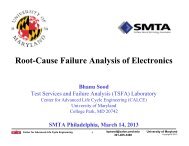
CAF Failure Mode• Dendritic failures in the bond-plylayers, particularly in the 106bondply• “Triple Point” failures occur in theinterstitial space between theindividual filaments, likely causedby a capillary void duringimpregnation process• 106 glass tightly bound anddifficult to “wet” with resin andsusceptible to capillary voids• Capillary voids trap moisture andionic contaminants leading to CAFformation106 Glass BundlesOrthogonal View of GlassbundlesGlass FilamentCapillary Void17
18Spread vs Non-Spread106 Glass (40X) 1037 Glass (50X)Glass weaves such as 1037, 1067, 1078 offer advantages over traditional weavessuch as 106 during prepreg impregnation by minimizing the occurrence of capillaryvoids1037 Glass 106 Glass
CAF Test Results (Two Glass Suppliers)Glass Supplier “A”Glass Supplier “B”No Failures!Hollow Fiber in GlassCapillary Void
A-Type Glass Failure AnalysisOrthogonal Hollow-FiberRogers Confidential
Theta(MCL-HE-679G)
PRODUCT OVERVIEW
Product OverviewFeaturesHalogen FreeBroad Range of ThicknessesLow Insertion LossCAF ResistantLow Z-Axis CTE<strong>High</strong> Tg / Lead Free Process CompatibleBenefits• Meets Future EnvironmentalConcerns• Design Flexibility• Signal Integrity• Long Term MLB Reliability• Superior Thermal / MechanicalReliability• <strong>High</strong> Temperature ProcessingCapability• Ease of Fabrication• Meets Environmental Concerns
Product Line PropertiesMid Loss Low Loss Ultra-Low LossPropertiesUnitsTheta(MCL-HE-679G)(MCL-FX-2)Under DevelopmentMaterial Type Halogen-Free Mid-Loss Low LossUltra LowLoss LamUltra LowLoss Bond PlyDk @ 1GHz 3.90 – 4.10 3.30 - 3.40 3.02 2.94Df @ 1GHz 0.008 – 0.010 0.002 - 0.003 0.0016 0.003Tg (TMA) °C 180 – 190 175 – 185 - 170Tg (DMA) °C 210 – 220 210 - 220CTE Z (< Tg) ppm/°C 35 - 45 48 - 55 58 50CTE Z (> Tg) ppm/°C 190 – 220 80 – 130UL Flammability UL-94 V-0 V-0 V-0 -IPC4101C Slash Sheet /127, /128/, /130 /102
Transmission Line Characterization3-Layer Stripline Structure0.008” Core/0.008” PP½ oz STD “Shiny” Cu50 Ω Strip-line#4 #3 #2PhenolicTheta electrical performance comparable to best-in-class mid loss products
伝 送 損 失 (dB/m)Transmission Line Characterization vs. Cu Foils-10HE-679G+HVLP foil-30HE-679G+LP foilHE-679 G+RT foilD-4+Std foilHE-679 G+Std foil-500 2 4 6 8 10・Loss of HE-679G using VLP or RT is the 周 波 same 数 (GHz) as that of D-4 material using Std.・The reduction of transmission loss is possible by using HVLP.
Laminate Electrical Properties
Prepreg/Bondply Electrical Properties
APPLICATIONS
Tested Applications• 26-Layer, Server CAF/Pb-Free Reflow Test Vehicle– 260C, 10x Reflow, CAF Test Vehicle (0.8, 1.0 mm pitch)• 18-Layer, 3+N+3 IST Coupon (Advanced Technology ProductDesigns)– 260C x 9, 100% pass 1000 cycles @ 150C• 28-Layer Carrier Class Router OEM Test Vehicle– Internal 2 oz plane layers, 1mm pitch BGA, 10x 260C Reflow, 2 week35C/85%RH precondition• 12-Layer 3+N+3 stacked microvia Design– Stacked microvias, 4x lamination, blind/buried vias• 18-Layer 1+N+1 Blind-Buried Microvia Test Vehicle– 10x 260C reflow, 10x no bake solder floats, 6x260C precon + IST 1000Cycle @150C + IST 100 Cycle @190C
26-Layer PCB TV26-Layer Server Class Line Card TV26-Layer Test Vehicle• 26 Layer PCB• 0.130” Thick• 0.010” (0.30mm) Smallest Hole• 0.8, 1.0 mm Pitch• 0.019” Web Thickness• 13:1 Aspect RatioJEDEC 260C Reflow ProfileHorizontal Section 10x Reflow
CAF CouponWall to Wall Spacing0.48mm0.68mm0.53mm0.74mmTheta passed all 4 conditions shown above thru 600 hours (for Servers and Storage)testing at Endicott Interconnect Labs following IBM test requirements
18-Layer, 3+N+3 IST OEM Coupon (AdvancedTechnology Product Designs)Thermal Analysis Unit ResultsT G (TMA) °C 175.49x260C IST @ 150C CTF 1000
Carrier Class Router• 28L, 0.145” Thick• 2 oz plane layers• Passed Test parameters– 260̊C, 10x Reflow CSAM– 35̊C /85%RH 2 week precon– CAF (1000hr,1.0mm BGA)– HATSThermal Analysis Unit ResultsT G (TMA) °C 185. 4CTE Z (TMA), pre-Tg ppm/°C 55.02CTE Z (TMA), post-Tg ppm/°C 260.4CTE Z (TMA), 50 – 260C % 2.63%T260 min >30 min
Eye Brow Crack Test VehicleThermal Analysis Unit ResultsT G (TMA) °C 175.31CTE Z (TMA), pre-Tg ppm/°C 57.47CTE Z (TMA), post-Tg ppm/°C 294.8CTE Z (TMA), 50 – 260C % 3.18%T260 min 45.9 minTheta passes 6x solder floats 288C (no preconditioning) without anyevidence of eyebrow cracks, competitive materials fail even with prebakes
3+N+3 Liquid-Liquid Thermal Shock (B)Thermal Analysis Unit ResultsT G (TMA) °C 171.70CTE Z (TMA), pre-Tg ppm/°C 55.8CTE Z (TMA), post-Tg ppm/°C 278.6CTE Z (TMA), 50 – 260C % 3.096%T260 min 16.33
1+N+1 Blind-Buried Stacked Microvia TV• 18 Layers• Thickness: 0.085” (2.16mm)• 2 lamination cycles• Stacked via over Buried Via• Passed Test Parameters:– IST coupons (150C + 190C)– 10x 260̊C JEDEC LFA Reflow18-Layer, 0.085” (2.16mm) thicknessThermal Analysis Unit ResultsT G (TMA) °C 174.42IST @ 150C +IST @190CLead-Free AssemblyJEDEC STDCTF 1000+/100+# of Pass 10X+Solder Floats (no bake) # of Pass 10X
FABRICATION
Processing• Prepreg Shelf-Life/Storage• Lamination• Drilling• Desmear
Precautions in handlingPrepreg Shelf-Life/Storage• The shelf life of prepreg is 3 months after the date ofshipping with controlled condition in the moisture barrierpacking (aluminum laminated bag).• Storage Recommendations: 20+/-5 o C(68+/-9 o F),
Lamination Process of HE-679GLamination Cycle• The press cycle should be adjusted in order to attain a Tg of175 o C(347 o F) or more (by TMA)• The product temperature should reach 190 o C(374 o F). Theminimum requirement should be that the producttemperature exceeds 180 o C(356 o F) for more than 80minutes. (Must ; ref. Fig.)• Product Heating Rate; 2.5-5.0 o C /min at 60-130 o C• Apply Full Pressure (2.5-4.0 MPa) before product reaches110 o C
Products Temperature ( o C)Lamination Process of HE-679GPressure (MPa)Lamination Cycle200Vaccuum Condition: under 4.0mmHg190℃12Keep more than 180 o C(356 o F),more than 80min. in products11101509810050Apply Full Pressure below 110̊Cheating rate: 3-4 o C/min.(6-7 o F)(80 o C~130 o C(176-266 o F))Product pressure: 3MPa(427psi)7654320.4-0.7MP(50-85psi) for 27min.10 Press timing: 110-130 o C(230-266 o F)00 30 60 90 120 150 180 210 240Time (min.)Fig. Recommended press condition
Desmearing processDesmearProcessChemicalsTemp.( o C)Duration (Min.)Swelling Swelling dip Securiganth P 70 2.5 – 5Etching Concentrate Compact CP 70 5 – 7Neutralization Securiganth P-500 40 5Theta desmear rate is faster than FR-4 in permanganate processMaterial Sample:50mm X 50mm (withoutcopper), N=5Chemistry:Rohm and Haas
Desmear: Plasma vs. PermanganatePlasma penetration intoglass bundlesPermanganate results invirtually no wicking
FX-2
PRODUCT OVERVIEW
Product OverviewFeatures<strong>High</strong> Tg (175 – 185C)/ Lead Free ProcessCompatibleLow Insertion Loss (50% lower than FR-4)Dk – 3.4; Df – 0.0026 (1 GHz)CAF ResistantLow Z-Axis CTE – 45 ppm/C ( 10 GbpsLong Term MLB ReliabilitySuperior Thermal / MechanicalReliability
Product Line-Up of MCL-FX-2Laminate Electrical PropertiesActualCode name Copper foilRCEstimated DkEstimated DfConstructionthickness(um)(wt%)- (inch) (mm) (inch) 1 GHz 3 GHz 5 GHz 10 GHz 1 GHz 3 GHz 5 GHz 10 GHz0.05 0.002 1037 x 1 71(69- 73) 0.050 0.0020 3.24 3.24 3.23 3.22 0.0023 0.0028 0.0036 0.0044Y0.05 0.002 1067 x 1 63(61- 65) 0.050 0.0020 3.43 3.42 3.41 3.39 0.0024 0.0034 0.0042 0.0053M0.06 0.002 1078 x 1 54(52- 56) 0.057 0.0022 3.44 3.43 3.42 3.41 0.0026 0.0036 0.0045 0.00550.06 0.002 Standard 1080 x 1 54(52- 56) 0.058 0.0023 3.44 3.43 3.42 3.41 0.0026 0.0036 0.0045 0.005512 (3/8oz.)M0.08 0.003 1078 x 1 64(62- 66) 0.076 0.0030 3.43 3.42 3.41 3.39 0.0024 0.0034 0.0042 0.005318 (0.5oz.)0.08 0.00335 (1oz.)1080 x 1 64(62- 66) 0.078 0.0031 3.43 3.42 3.41 3.39 0.0024 0.0034 0.0042 0.00530.1 0.004 70 (2oz.) 3313 x 1 54(52- 56) 0.100 0.0039 3.44 3.43 3.42 3.41 0.0026 0.0036 0.0045 0.00550.11 0.004 1037 x 2 71(69- 73) 0.100 0.0039 3.24 3.24 3.23 3.22 0.0023 0.0028 0.0036 0.0044Y0.11 0.004 1067 x 2 63(61- 65) 0.100 0.0039 3.43 3.42 3.41 3.39 0.0024 0.0034 0.0042 0.00530.13 0.005VLP2116 x 1 54(52- 56) 0.125 0.0049 3.44 3.43 3.42 3.41 0.0026 0.0036 0.0045 0.00550.2 0.008 12 (3/8oz.) 3313 x 2 54(52- 56) 0.200 0.0079 3.44 3.43 3.42 3.41 0.0026 0.0036 0.0045 0.00550.26 0.010 18 (0.5oz.) 2116 x 2 54(52- 56) 0.250 0.0098 3.44 3.43 3.42 3.41 0.0026 0.0036 0.0045 0.00550.4 0.01635 (1oz.)1501 x 2 54(52- 56) 0.397 0.0156 3.44 3.43 3.42 3.41 0.0026 0.0036 0.0045 0.00550.5 0.020 1501 x 2 + x 1 54(52- 56) 0.497 0.0196 3.44 3.43 3.42 3.41 0.0026 0.0036 0.0045 0.00550.6 0.024 profile free 1501 x 3 54(52- 56) 0.596 0.0235 3.44 3.43 3.42 3.41 0.0026 0.0036 0.0045 0.00550.8 0.032 12 (3/8oz.) 1501 x 4 54(52- 56) 0.794 0.0313 3.44 3.43 3.42 3.41 0.0026 0.0036 0.0045 0.00551.0 0.040 18 (0.5oz.) 1501 x 5 54(52- 56) 0.993 0.0391 3.44 3.43 3.42 3.41 0.0026 0.0036 0.0045 0.00551.2 0.04735 (1oz.)1501 x 6 54(52- 56) 1.191 0.0469 3.44 3.43 3.42 3.41 0.0026 0.0036 0.0045 0.00551.4 0.055 1501 x 7 54(52- 56) 1.390 0.0547 3.44 3.43 3.42 3.41 0.0026 0.0036 0.0045 0.00551.6 0.063 1501 x 8 54(52- 56) 1.588 0.0625 3.44 3.43 3.42 3.41 0.0026 0.0036 0.0045 0.0055*This line-up plan is as of Apr.’11. The line-up may be changed for some reasons.
Product Line-Up of GFA-2 (Prepreg)Prepreg Electrical PropertiesNominalthickness(mm)Glass StylePrepregType nameRC(wt%)After lam. Thickness Estimated Dk Estimated Df(mm) (inch) 1 GHz 3 GHz 5 GHz 10 GHz 1 GHz 3 GHz 5 GHz 10 GHz0.04 #1037 KZNC 69 - 73 0.050 0.0020 3.24 3.24 3.23 3.22 0.0023 0.0027 0.0036 0.0044#1067 KYMC 61 - 65 0.050 0.0020 3.43 3.42 3.41 3.39 0.0024 0.0034 0.0042 0.0053#1067 KYUC 71 - 75 0.072 0.0028 3.24 3.24 3.23 3.22 0.0023 0.0027 0.0036 0.00440.06 #1080 KUQC 62 - 66 0.078 0.0031 3.43 3.42 3.41 3.39 0.0024 0.0034 0.0042 0.0053#1080 KUMC 66 - 70 0.089 0.0035 3.35 3.34 3.33 3.31 0.0024 0.0028 0.0041 0.0052#1080 KUPC 70 - 74 0.104 0.0041 3.24 3.24 3.23 3.22 0.0023 0.0027 0.0036 0.0044#1078 KRQC 62 - 66 0.076 0.0030 3.43 3.42 3.41 3.39 0.0024 0.0034 0.0042 0.0053#1078 KRMC 66 - 70 0.087 0.0034 3.35 3.34 3.33 3.31 0.0024 0.0028 0.0041 0.00520.08 #3313 KGHB 54 - 58 0.106 0.0042 3.44 3.43 3.42 3.41 0.0026 0.0036 0.0045 0.0055#3313 KGKB 56 - 60 0.112 0.0044 3.43 3.43 3.42 3.41 0.0025 0.0032 0.0043 0.00540.1 #2116 KAGB 52 - 56 0.125 0.0049 3.44 3.43 3.42 3.41 0.0026 0.0036 0.0045 0.00550.15 #1501 KQGB 50 - 54 0.188 0.0074 3.48 3.47 3.46 3.45 0.0029 0.0040 0.0050 0.0061**The dielectric thickness after lamination is defined as the thickness of one sheet of prepreg when theresin flow is within 0%. This value changes according to the press condition and inner-layer pattern.***This line-up plan is as of Apr.’11. The line-up may be changed for some reasons.
Transmisson Loss (dB/m)FX-2 Transmission Loss (Various copper)Transmission Line Characterization vs. Cu Foils0-20FX-2+HVLP foilD-6+HVLP foil-40FX-2+LP foil-60FX-2+RT foil0 5 10 15 20Frequency (GHz)FX-2+Std foil・Loss of FX-2 using VLP or RT is the same as that of D-6 material using HVLP.・The reduction of transmission loss is possible by using HVLP.
SPP methodShort Pulse Propagation (SPP) Method, Dk/DfEvaluation BoardSMASPP2z Test VehicleEvaluation Line: Single end strip lineConstruction3cmPulse wave analysis Equipment9.8cm12345678FillFillFillFill1/2oz Cu (STD)1x2116 54% resin1/2oz Cu (PF)Core1x1078, 72% resin1/2oz Cu (PF)1x1078, 72% resin1/2oz Cu (VLP)Core1x2116 54% resin1/2oz Cu (VLP)1x2116 54% resin1/2oz Cu (VLP)Core1x2116 54% resin1/2oz Cu (VLP)1x2116 54% resin1/2oz Cu (STD)<strong>High</strong> RC(S3)Low RC(S6)
SPP Extracted Dk/DfShort Pulse Propagation (SPP) Method, Dk/DfFX-2Block Frequency Dk Df1GHz 3.118 0.00503GHz 3.106 0.005310GHz 3.095 0.005320GHz 3.087 0.00641GHz 3.482 0.00543GHz 3.469 0.005810GHz 3.454 0.006220GHz 3.444 0.0074S3(Resin rich)S6(Resin poor)HE-679GBlock Frequency Dk DfS3(Resin rich)S6(Resin poor)1GHz 3.675 0.01483GHz 3.634 0.016110GHz 3.588 0.016520GHz 3.562 0.01691GHz 3.950 0.01153GHz 3.917 0.012410GHz 3.880 0.012520GHz 3.858 0.0134
Heat resistance of high layer count board26-Layer Lead-Free TVLayer counts : 26 layer boardTotal thickness : 4.1mmAfter reflow 260degC 10sec x 6 timesDia.0.25mm Dia.0.30mmPrecondition:E-0.5/110 C-24/85/85%RHReflow260degC X 10 timesNo blister & No delaminationobserved
CAF CouponWall to Wall Spacing0.48mm0.68mm0.53mm0.74mmFX-2 passed all 4 conditions shown above thru 600 hours (for Servers and Storage)testing following IBM test requirements
Thermal AnalysisTest Description Unit Method ResultsFX-2 Cycle 1 Cycle 2T G (TMA) °C IPC TM 650 2.4.41 191.15 193.7CTE Z (TMA), pre-Tg ppm/°C IPC TM 650 2.4.41 73.26 72.21CTE Z (TMA), post-Tg ppm/°C IPC TM 650 2.4.41 130.6 127.8CTE Z (TMA), 50 – 260C % IPC TM 650 2.4.41 2.177 2.126T260 (with external copper) min IPC TM 650 2.4.24.1 Pass PassT288 (with external copper) min IPC TM 650 2.4.24.1 12.39 10.64
Ultra-Low Loss <strong>High</strong> <strong>Speed</strong> <strong>Digital</strong>Material System
Emerging Market Needs• We are seeing an emerging market opportunity forinterconnects at speeds of 25 Gb/s and higher withinterconnect lengths up to 30”– <strong>High</strong> <strong>Speed</strong> Computing– SANS– IP Routers / Switches– ATE– Optical Networks– Backplanes and large system cards12/5/2012 Rogers Proprietary 57
12/5/2012 Rogers Proprietary 58Emerging Market Needs• No existing material system available todaymeets all needs- Electrical modeling indicates a need for- Dk