SW500 Serial Protocol.pdf - PASCO Scientific
SW500 Serial Protocol.pdf - PASCO Scientific
SW500 Serial Protocol.pdf - PASCO Scientific
Create successful ePaper yourself
Turn your PDF publications into a flip-book with our unique Google optimized e-Paper software.
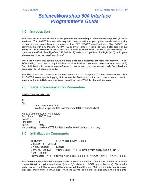
<strong>PASCO</strong> scientific <strong>SW500</strong> <strong>Protocol</strong> Rev 2.0 18.11.03ScienceWorkshop 500 InterfaceProgrammer’s Guide1.0 IntroductionThe following is a specification of the protocol for controlling a ScienceWorkshop 500 (<strong>SW500</strong>)interface. The <strong>SW500</strong> is a versatile acquisition device with multiple input channels and samplingmodes, whose data interface conforms to the IEEE RS-232 specifications. The <strong>SW500</strong> cancommunicate with any Macintosh, IBM-PC, or other computer equipped with a standard RS-232interface. All commands to the <strong>SW500</strong> are 1 byte op-codes with 0 or more operand bytes. Allbytes are specified Most-Significant-Bit-Left (bit 7) and Least-Significant Bit-Right (bit 0). All signedintegers are in two’s-compliment format.When the <strong>SW500</strong> first powers up, it executes boot code in permanent read-only memory. In thisROM mode, it can accept only identification, download, and execute commands (see section 2).Once initialized with downloadable software, it then executes the downloaded code from RAM andcan accept its full command suite.The <strong>SW500</strong> can also collect data when not connected to a computer. The host computer can placethe <strong>SW500</strong> into a special logging state where the front panel button can then be used to controllogging in the field. Data can later be retrieved from the <strong>SW500</strong> by the host computer.2.0 <strong>Serial</strong> Communication ParametersRS-232 Data Signals UsedTxRxCTS(from Host to interface)Interface suspends data transfer when CTS is raised by host.RS-232 Communication ParametersBaud Rate: 19,200 baudData Bits: 8Stop Bits: 1Parity: noneHandshaking: hardware/CTS for data transfer from interface to host only3.0 Initialization CommandsIdentify (RAM or ROM mode)Command: 0 x 01Operand(s): noneReturn Data: “<strong>SW500</strong>i__” + 4-Byte Version Code (if inROM mode)“<strong>SW500</strong>i__” + 4-Byte Version Code + “RAM” (if in RAM mode)This command identifies the interface model number and version. The model number must be theconstant 8-byte string indicated above (where “_” indicates an ASCII space character). The versioncode may vary with the revision of the unit, but will be of the form “1.0_”. If the interface is alreadyinitialized and running in RAM mode, then the Identify command will also return three flag bytes1 of 10
<strong>PASCO</strong> scientific <strong>SW500</strong> <strong>Protocol</strong> Rev 2.0 18.11.03after the version code. These bytes must be “RAM”. If the “RAM” flag bytes are not returned, thenthe interface is running in ROM mode and requires download and execute commands.Download (ROM mode only)Command: 0 x 02Operand(s): Download RecordReturn Data: Checksum ByteThis command downloads one code/data record to be loaded into RAM on the interface. Theformat of a download record mirrors the Motorola S-Record format:Bytes Description1 Number of bytes (address,code/data,checksum) to follow (255 maximum).3 Initial address for code/data bytes (unsigned integer).n Code/Data bytes1 Checksum byteThe download records for the <strong>SW500</strong> reside in the file “<strong>SW500</strong>RAM.S28”, available from <strong>PASCO</strong>scientific (www.pasco.com). Each field in the download record is the binary equivalent of the hexvalues in an ASCII Motorola S-Record. (Only records beginning with the characters “S2” need to beconverted to binary and downloaded.) One download command is issued for each “S2” S-Record ina download module. The <strong>SW500</strong> computes a checksum on the address and code/data bytes of therecord as they are received. The resulting checksum byte is returned to acknowledge receipt of therecord. Any difference between the returned checksum byte and the downloaded checksum byteindicates that the record should be re-sent or that an unreliable serial connection exists. AnExecute command may only be issued once all “S2” records from <strong>SW500</strong>RAM.S28 have beendownloaded and acknowledged. The Download command will be ignored when the interface isrunning in RAM mode.Execute (ROM mode only )Command: 0X03Operand(s): noneReturn Data: Acknowledge BytesExecute the downloaded RAM code in the interface. (This places the interface into RAM mode.)Appropriate Download commands must have been issued prior to this command. The Executecommand will be ignored when the interface is running in RAM mode.Reset (RAM mode only)Command: 0x4Operand(s): noneReturn Data: noneReset the entire interface to power-on state. All download code, buffered data, and mode settingsare cleared. After this command, the interface will be running in ROM mode.4.0 Sampling Setup Commands (RAM mode only)2 of 10
<strong>PASCO</strong> scientific <strong>SW500</strong> <strong>Protocol</strong> Rev 2.0 18.11.03Log State RetrieveCommand: 0x16Operands: noneReturn Data: Number of Bytes (unsigned short)State BytesThis command returns log mode state data to the host from a specific RAM area. The maximumnumber of bytes that can be retrieved is 3072. The number and order of bytes retrieved are exactlyas stored with the last Log State Store command.5.0 Sampling Control CommandsStart SamplingCommand: 0x21Operands: noneReturn Data: sample data records (see format below)This command starts continuous sampling based on the current sampling configuration. Buffer iscleared first. While sampling progresses, no other command which returns data should be issued;as the returned data would be interspersed with data bytes form the buffer. Sampling produces anumber of different types of data records. These are variable-length records whose type isindicated by the upper nibble of the first data byte. The following are descriptions of the recordtypes:Clocked Sample RecordThis information is generated at the clocked sample period defined in the Rate Select command:0x1d(d= digital channel states 1,2. Bit 0=ch1, Bit 1=ch2)Analog Channel A Sample (2 bytes, signed, representing +/- 10v or +/- 1V w/gain)Analog Channel B Sample (2 bytes, signed, representing +/- 10v or +/- 1V w/gain)Analog Channel C Sample (2 bytes, signed, representing +/- 10v)Digital Channel 1 Count (2 bytes, unsigned, representing number of falling edges)Digital Channel 2 Count (2 bytes, unsigned, representing number of falling edges)The digital states are always included in an analog sample record. If a particular analog inputchannel is not selected, then the bytes for that sample are omitted, and the order remains thesame. If a particular digital channel is not selected for counting, then the bytes for that sample areomitted, and the order remains the same. When a digital counter value is reported, then thecounter is cleared. Thus the count is a count of falling edges detected in the last clock period.To convert from raw analog samples to voltage, multiply by 10 and divide by 32767.Digital Event RecordThis information is generated each time a change in the state of any event-selected digital I/Ochannel is detected:0x2dtime of event(d=digital channel states 1,2. Bit 0=ch1, Bit 1=ch2)(4 bytes, unsigned: sample periods since last Start Sampling)Pause RecordThis information is generated each time a pause command is received. This record flags wherepause commands are received in the data stream:0x405 of 10
<strong>PASCO</strong> scientific <strong>SW500</strong> <strong>Protocol</strong> Rev 2.0 18.11.03Motion Timer RecordThis information is generated at the period defined in the Rate Select command when the motiontimer is selected:0x50timer valuetime of echo(2 bytes, unsigned: µsec between pin and echo)(4-bytes, unsigned: sample periods since last Start Sampling)Sample State RecordThis information is generated in response to a Check Sample State command, or to report a bufferevent such as the buffer becoming full, the trigger event being reached, or a data run ending:0x6s (s=state flags)bit 0=Interface has detected the trigger condition.bit 1=Interface buffer has become full, and sampling has stopped automaticallybit 2=Interface is waiting for a trigger condition to begin samplingbit 3=Interface has ended a recorded data run.6 of 10
<strong>PASCO</strong> scientific <strong>SW500</strong> <strong>Protocol</strong> Rev 2.0 18.11.03Trigger Time Offset RecordThis information is generated when a trigger condition is reached. This will be the first record sentfrom the interface prior to the pre-trigger data. The time stamp offset in this record should be usedto adjust all other time stamps that follow (in Digital Event and Motion Timer records) in a givenrecorded run. This will stamp the pre-trigger data with negative times, with time = 0 being the triggerpoint.0xF0time stamp offset (4-bytes, unsigned:sample periods since last Start Sampling)Stop SamplingCommand: 0x22Operands: noneReturn Data: noneThis command stops all sampling and digital pinging. Sampling options are preserved. Buffercontents will be preserved and transferred. Note that sampling can stop automatically if the bufferbecomes full, in which case a Sample State Record will appear at the end of the sample data.Pause SamplingCommand: 0x23Operands: noneReturn Data: noneThis command pauses all sampling and digital pinging. The buffer is cleared. A pause eventrecord is added to the buffer. Has no effect if not started sampling. Clocked samples, eventreporting, motion sensor pinging, and sample time accumulation are suspended.Resume SamplingCommand: 0x24Operands: noneReturn Data: noneThis command resumes sampling and digital pinging after a pause. Data is written to the bufferfollowing the pause record. This command should only be used after sampling and pausing.Reset BufferCommand: 0x25Operands: noneReturn Data: noneThis command resets the buffer to an empty state.Check Buffer StateCommand: 0x26Operands: noneReturn Data: number of data bytes in buffer (2 bytesunsigned)Number of logged data runs in buffer (1 byte unsigned)This command returns the number of data bytes and number of logged runs in the buffer. Databytes may be left in the buffer after sampling has been stopped. They are not transferred to thehost unless the host issues a Read Buffer command after stopping sampling. Multiple data runsare accumulated in the buffer by log commands issued by the user via the front panel button on theinterface.7 of 10
<strong>PASCO</strong> scientific <strong>SW500</strong> <strong>Protocol</strong> Rev 2.0 18.11.03One-Shot SampleCommand: 0x27Operands: noneReturn Data: 1 Clocked Sample Record and (optionally) 1Motion Timer Record.This command performs a single sample of each selected analog channel and digital counter. Alsoperforms one ping-echo timing of a motion sensor if selected. The selections in the last InputSelect command are used for one-shot sampling. If no analog channels or digital counters areselected, then a one-byte clocked sample record is generated containing only the digital states. Ifthe motion timer is not selected, then no motion timer record is generated. See the Start Samplingcommand for a description of the Clocked Sample Record and Motion Timer Record.Write DigitalCommand: 0x28Operands: Operand Byte 1bit 0-3 Unusedbit 4 Digital Channel 1 Databit 5 Digital Channel 2 Databit 6 Digital Channel 1 Output Enable (0=enable)bit 7 Digital Channel 2 Output Enable (0=enable)Return Data: noneThis command sets the digital channel data bits and output enabling state. The data bits will bestored, but not output if the output enable bit for a channel is set to 1. If output is disabled for achannel, the channel is an input.Read BufferCommand: 0x29Operands: noneReturn Data: sample data records (see format in Start Sampling)This command causes any data bytes in the buffer to be transmitted to the host and immediatelycleared from the interface. Data bytes may remain in the interface buffer after a Stop Samplingcommand is issued. The Check Buffer State command reports how many data bytes are available.Data bytes will also be in the buffer when the interface has been used for logging away from thecomputer. In this later case, the Read Buffer Block command can provide a more reliable transfer ofa large amount of logged data.Check Sample StateCommand: 0x2AOperands: noneReturn Data: sample state record (see format in Start Sampling)This command causes a sample state record to be inserted into the data stream. This command isuseful for checking the interface state during prolonged waits for digital events, or very slow-clockedsamples.8 of 10
<strong>PASCO</strong> scientific <strong>SW500</strong> <strong>Protocol</strong> Rev 2.0 18.11.03Enable Data LoggingCommand: 0x2BOperands: noneReturn Data: noneThis command causes the interface to enter low-power sleep mode in preparation for disconnectionof power and data cables, and eventual data logging. In this mode, the front-panel button isenabled so that the user may start and stop data logging recording to create multiple data runs.Data transmission to the host is disabled.Disable Data LoggingCommand: 0x2COperands: noneReturn Data: noneThis command causes the interface to wake up from low-power sleep mode after data logging. Thefront-panel button is disabled. The Check Buffer State command can be used to determine if (andhow much) log data is in the interface. The Read Buffer or Read Buffer Block command will causethe interface to transmit the buffer data.Read Buffer BlockCommand: 0x2DOperands: Operand Bytes 1-2 Start Position (unsigned )Operand Bytes 3-4 End Position (unsigned)Return Data: sample data record bytes + 1 byte checksumThis command causes a range of data bytes from the buffer (specified by the start and endposition) to be transmitted to the host. The data remains in the buffer on the interface. A startposition of 0 indicates the first byte in the buffer. The Check Buffer State command is used todetermine the maximum end position. To read the entire buffer, request blocks with successivestart/end positions (512 byte blocks are recommended). Note that a data record may be splitbetween successive block reads. Each block will be followed by a single checksum byte (anunsigned byte which is the sum of all unsigned data bytes). If a computed checksum does notmatch the transmitted checksum, then a block may be re-requested any number of times. Once alldata blocks have been successfully read, the buffer can be cleared with a Reset Buffer command.6.0 Command Sequence ExamplesDetecting and Downloading- Send Identify command- Wait for all returned data bytes- Verify the interface model number and that the interface is in ROM mode(if already in RAM mode, then downloading is not necessary)- Read lines from the file <strong>SW500</strong>RAM.S28, convert to binary and send a Downloadcommand for each line- After each Download command, wait for a checksum byte and verify it- After all download commands, send an Execute command- Send Identify command again, wait for returned data bytes and verify RAM modeContinuous Sampling- Send Trigger Select command (to set or clear a trigger)- Send Input Select command- Send Rate Select command (use large buffer)- Set Rotary Motion Resolution (if using an RMS)- Send Start Sampling command9 of 10
<strong>PASCO</strong> scientific <strong>SW500</strong> <strong>Protocol</strong> Rev 2.0 18.11.03- Periodically read and decode sample data records from the serial port. (Note that a sampledata record may be split between two serial port reads on the host computer. Save a partialrecord from the end of one serial port read and add it to the beginning of the next serial portread. The expected length of each record type can be computed based on the selectedchannels.)- Send Stop Sampling command.Burst (Scope) Sampling- Send Trigger Select command (to set or clear a trigger)- Send Input Select command (select analog channels only)- Send Rate Select command(clock period should = 1, use small buffer)- Send Start Sampling command.For higher sample rates (10 KHz and higher) it is likely that the interface will fill the smallbuffer and automatically stop sampling (indicated by a Sample State record at the end ofthe data).- Read and decode sample data from the serial port until either a Sample State recordindicates that sampling stopped automatically, or the desired number of samples has beenread.- If sampling did not stop automatically, send a Stop Sampling command.- Repeat all of the above steps for additional scope traces.10 of 10


