
You also want an ePaper? Increase the reach of your titles
YUMPU automatically turns print PDFs into web optimized ePapers that Google loves.
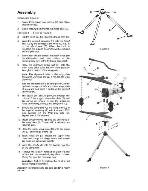
AssemblyReferring to Figure 3:1. Screw three tripod pole bases (M) onto threetripod poles (L).2. Screw tripod poles (M) into the tripod seat (D).For steps 3 – 13 refer to Figure 4.3. Pull the knob (D 1 , Fig. 3) on the tripod seat and4. Insert the support assembly (F) onto the tripodseat (D) by first pulling out the knob (D 1 , Fig. 3)on the tripod seat (D). When the knob isreleased, the support assembly will be securedto the tripod seat.5. Screw four double-ended threaded studs (M)(short-threaded end) into bottom of thehousing base (C 1 ) of the hydraulic pump unit.6. Place the hydraulic pump unit (C) onto thelower wing plate such that the studs protrudethrough the bottom of the wing plate.Note: The alignment holes in the wing plateand pump unit must line up. If not, flip the wingplate over.7. With the assistance of a second person, lift thehydraulic pump unit (C) and lower wing plate(J) as a unit and place it on top of the supportassembly (F).8. The studs (M) should protrude through thebottom of the support assembly plate (F) andthe spring pin should fit into the alignmentholes of the wing plate (J) and pump unit (C).9. Secure the pump unit (C) and wing plate (J) tothe support assembly (F) with four each M12lock washers (N) and M12 hex nuts (O).Tighten with a 7/8" wrench.10. Mount swage blocks (E) onto the end-holes ofthe wing plate (J). These will be adjusted asrequired later.11. Place the upper wing plate (H) onto the pumpunit (C) and swage blocks (E).12. Insert hinge pin (G) though the upper wingplate and pump unit hinge holes and securethe hinge pin with cotter pin (R).13. Insert the handle (K) into the handle cap (C 2 )on the pump unit.14. Remove the factory installed oil plug (P) andreplace with the vented oil plug (P) and rubberO-ring (Q) from the hardware bag.Important: Failure to replace the oil plug willcause improper operation.Assembly is complete and the pipe bender is readyfor use.D D 1LFigure 3Figure 4M7