Manual - JET Tools
Manual - JET Tools
Manual - JET Tools

Create successful ePaper yourself
Turn your PDF publications into a flip-book with our unique Google optimized e-Paper software.
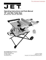
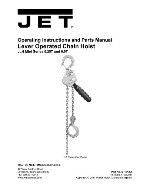
Operating Instructions and Parts <strong>Manual</strong>Lever Operated Chain HoistJLH Mini Series 0.25T and 0.5T1/4 Ton model shownWALTER MEIER (Manufacturing) Inc.427 New Sanford RoadLaVergne, Tennessee 37086 Part No. M-181205Ph.: 800-274-6848 Revision A 06/2011www.waltermeier.comCopyright © 2011 Walter Meier (Manufacturing) Inc.
Warranty and ServiceWalter Meier (Manufacturing) Inc., warrants every product it sells. If one of our tools needs service or repair, one ofour Authorized Service Centers located throughout the United States can give you quick service. In most cases, anyof these Walter Meier Authorized Service Centers can authorize warranty repair, assist you in obtaining parts, orperform routine maintenance and major repair on your <strong>JET</strong>® tools. For the name of an Authorized Service Center inyour area call 1-800-274-6848.MORE INFORMATIONWalter Meier is consistently adding new products to the line. For complete, up-to-date product information, check withyour local Walter Meier distributor, or visit waltermeier.com.WARRANTY<strong>JET</strong> products carry a limited warranty which varies in duration based upon the product (MW = Metalworking, WW =Woodworking).WHAT IS COVERED?This warranty covers any defects in workmanship or materials subject to the exceptions stated below. Cutting tools,abrasives and other consumables are excluded from warranty coverage.WHO IS COVERED?This warranty covers only the initial purchaser of the product.WHAT IS THE PERIOD OF COVERAGE?The general <strong>JET</strong> warranty lasts for the time period specified in the product literature of each product.WHAT IS NOT COVERED?Five Year Warranties do not cover woodworking (WW) products used for commercial, industrial or educationalpurposes. Woodworking products with Five Year Warranties that are used for commercial, industrial or educationpurposes revert to a One Year Warranty. This warranty does not cover defects due directly or indirectly to misuse,abuse, negligence or accidents, normal wear-and-tear, improper repair or alterations, or lack of maintenance.HOW TO GET SERVICEThe product or part must be returned for examination, postage prepaid, to a location designated by us. For the nameof the location nearest you, please call 1-800-274-6848.You must provide proof of initial purchase date and an explanation of the complaint must accompany themerchandise. If our inspection discloses a defect, we will repair or replace the product, or refund the purchase price,at our option. We will return the repaired product or replacement at our expense unless it is determined by us thatthere is no defect, or that the defect resulted from causes not within the scope of our warranty in which case we will,at your direction, dispose of or return the product. In the event you choose to have the product returned, you will beresponsible for the shipping and handling costs of the return.HOW STATE LAW APPLIESThis warranty gives you specific legal rights; you may also have other rights which vary from state to state.LIMITATIONS ON THIS WARRANTYWALTER MEIER (MANUFACTURING) INC., LIMITS ALL IMPLIED WARRANTIES TO THE PERIOD OF THELIMITED WARRANTY FOR EACH PRODUCT. EXCEPT AS STATED HEREIN, ANY IMPLIED WARRANTIES ORMERCHANTABILITY AND FITNESS ARE EXCLUDED. SOME STATES DO NOT ALLOW LIMITATIONS ON HOWLONG THE IMPLIED WARRANTY LASTS, SO THE ABOVE LIMITATION MAY NOT APPLY TO YOU.WALTER MEIER SHALL IN NO EVENT BE LIABLE FOR DEATH, INJURIES TO PERSONS OR PROPERTY, ORFOR INCIDENTAL, CONTINGENT, SPECIAL, OR CONSEQUENTIAL DAMAGES ARISING FROM THE USE OFOUR PRODUCTS. SOME STATES DO NOT ALLOW THE EXCLUSION OR LIMITATION OF INCIDENTAL ORCONSEQUENTIAL DAMAGES, SO THE ABOVE LIMITATION OR EXCLUSION MAY NOT APPLY TO YOU.Walter Meier sells through distributors only. The specifications in Walter Meier catalogs are given as generalinformation and are not binding. Members of Walter Meier reserve the right to effect at any time, without prior notice,those alterations to parts, fittings, and accessory equipment which they may deem necessary for any reasonwhatsoever. <strong>JET</strong>® branded products are not sold in Canada by Walter Meier.2
Table of ContentsWarranty and Service..........................................................................................................................2Table of Contents ...............................................................................................................................3Warning .............................................................................................................................................4Introduction ........................................................................................................................................5Specifications (JLH-25/50) ..................................................................................................................6Unpacking ..........................................................................................................................................7Contents of the Carton .....................................................................................................................7Installation..........................................................................................................................................7Pre-Operation Inspection.....................................................................................................................7Inspecting the Load Chain................................................................................................................7Inspecting Hooks .............................................................................................................................8Other Inspections ............................................................................................................................8Operation ...........................................................................................................................................9Precautions................................................................................................................................... 10Maintenance .................................................................................................................................... 11Allowable Limits for Load Chain and Hooks ........................................................................................ 11Load Chain ................................................................................................................................... 11Hooks (Top and Bottom) ................................................................................................................ 11Troubleshooting ................................................................................................................................ 12Replacement Parts ........................................................................................................................... 12JLH Series Lever Hoists (JLH-25/50) .............................................................................................. 13Parts List: JLH-25 (0.25 Ton) ......................................................................................................... 14Parts List: JLH-50 (0.5 Ton) ........................................................................................................... 153
Warning1. Read and understand the entire owner’s manual before attempting operation. Failure to comply withinstructions and warnings may cause serious injury.2. This lever hoist is designed and intended for use by properly trained and experienced personnel only.If you are not familiar with the proper and safe operation of a lever hoist, do not use until propertraining and knowledge have been obtained.3. Do not use this lever hoist for other than its intended use. If used for other purposes, Walter Meier(Manufacturing) Inc., disclaims any real or implied warranty and holds itself harmless from any injurythat may result from that use.4. Do not use lever hoist to lift, support or transport people; or to lift or support loads over people.5. Do not exceed the rated capacity of the hoist.6. Do not attempt to extend the lever handle using a “cheater pipe” or any other such device.7. Do not strike the lever handle with a hammer or any other object.8. Do not use the chain as a sling. This may cause damage to the chain.9. Always inspect the lever hoist for damage prior to use. If hoist is damaged, do not use until it hasbeen repaired or replaced.10. Do not use more than one lever hoist to lift or move a load. If this is unavoidable, each hoist musthave the same capacity as the load to be moved.11. Never allow chain to “set” over sharp edges. All pulls or lifts must be made with straight chain that isfree of obstacles.12. If the lever handle is difficult to operate, then the load exceeds the capacity of the hoist. Reduce loador select a hoist of larger capacity.13. Do not use hoist if the chain is twisted, kinked or damaged.14. Do not operate hoist unless load is centered between top and bottom hooks.15. On hoists with the overload warning lever, do not use this device to measure load weight.16. Always take time to study the job to be performed and choose the safest method. Do not placeyourself or other people in an unsafe position.17. Always maintain your balance and firm footing when operating the lever hoist.18. Leave all internal maintenance and inspections to a qualified Walter Meier Service Center.19. Do not attempt to lengthen or repair load chain.20. Replace chain with factory replacement chain only. Do not use any other type of chain.21. If welding near the hoist, do not allow the chain or hook to be touched by a live electrode. Preventweld splatter upon the chain.22. Never use the hoist if either hook is stretched, deformed, or has a broken or missing safety latch.Always replace the safety latch and/or the hook before placing the hoist back in service.23. Be sure supporting structures and load-attaching devices used in conjunction with this lever hoistprovide an adequate safety factor to handle the rated load plus the weight of the equipment. If indoubt, consult a qualified structural engineer.24. Understand and follow all procedures as set forth in American National Standards titled “PerformanceStandard for <strong>Manual</strong>ly Lever Operated Chain Hoists.” ANSI/ASME HST-3M. This standard isavailable through the American Society of Mechanical Engineers, Three Park Ave., New York, NY10016, or visit www.ASME.org25. Keep visitors a safe distance from the work area. Keep children away.4
IntroductionThis manual is provided by Walter Meier (Manufacturing) Inc., covering the safe operation andmaintenance procedures for the <strong>JET</strong> JLH Mini Series Lever Hoists. This manual contains instructions oninstallation, safety precautions, general operating procedures, maintenance instructions and partsbreakdown. This tool has been designed and constructed to provide years of trouble free operation ifused in accordance with instructions set forth in this manual. If there are any questions or comments,please contact either your local supplier or Walter Meier. Walter Meier can also be reached at our website: www.waltermeier.com.Record your purchase information here for quick reference:Model No.: Stock No.: Serial No.:Purchased From:Date Purchased:5
Specifications (JLH-25/50)StockNumberDescriptionRatedCapcty.(ton)StandardLift(ft.)Min.Distancebetweenhooks (in.)“A”No.offallsLoadChainDiameter(mm)Lift perfull turn(in.)Lbs.Pullto LiftcapacityLeverLength(in.)“B”(in.)“C”Overallwidth(in.)“D”HookThroatOpening(in.)“E”NetWeight(lbs)181205 JLH-25-5 0.25 5 1.40 1 3.2 0.42 44.97 5.71 2.68 3.43 0.83 3.53181210 JLH-25-10 0.25 10 1.40 1 3.2 0.42 44.97 5.71 2.68 3.43 0.83 4.41181215 JLH-25-15 0.25 15 1.40 1 3.2 0.42 44.97 5.71 2.68 3.43 0.83 5.29181505 JLH-50-5 0.5 5 1.65 1 4.3 0.33 54.01 6.30 3.19 3.96 0.96 5.51181510 JLH-50-10 0.5 10 1.65 1 4.3 0.33 54.01 6.30 3.19 3.96 0.96 7.05181515 JLH-50-15 0.5 15 1.65 1 4.3 0.33 54.01 6.30 3.19 3.96 0.96 8.60NOTE: The above stock numbers are representative; chain is available in other lengths. Specify length whenordering.6
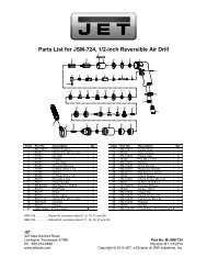
UnpackingOpen carton and check for shipping damage.Report any damage immediately to yourdistributor and shipping agent. Do not discardany shipping material until the Lever Hoist isassembled and running properly. Read thisentire instruction manual thoroughly for set-up,maintenance and safety instructions.Contents of the Carton1 Lever Hoist1 Owner's <strong>Manual</strong>1 Warranty CardInstallationSupport for the hoist may be hook, clevis pin,trolley, or beam clamp. Whatever method ofsuspension is chosen, the support componentsmust be rated equal to, or greater than thecapacity of the lever hoist. Supporting structures(such as I-Beams, etc.) should be installed byproperly licensed professional installers.Pre-Operation InspectionFigure 1Features and terminologyInspecting the Load Chain1. A chain stop must be attached to thesecond-to-last link on the slack end of thechain. See Figure 2.Do not operate the hoist witha twisted, kinked or damaged chain. Do notsplice the chain.2. Check that the chain does not twist along itslength from hoist to hook. If twist is presenton units with multiple falls, the hook must bepassed back through the chain loop toremove all twist in the chain.3. Replace the chain if links are stretched toolong or seriously worn on the surface,especially at the points where links contacteach other. See “Allowable Limits” on page12 for measuring chain elongation.4. Do not use a chain that is seriously rustedor cracked.5. Periodically apply a light coat of 30W oil tothe chain. This will create easier operationand prolong the chain’s life. For optimumresults, clean the chain with an acid-freesolution before oiling.Figure 27
The load chain supplied withyour <strong>JET</strong> lever hoist is designed,manufactured, and tested for proper fit anddurability. If chain should ever needreplacing, for your own safety use factoryreplacement chain only. Use of other thanfactory replacement chain may causeserious injury and/or damage to the leverhoist.Never extend load chain by welding a secondpiece to the original.Inspecting HooksIt is important to check top and bottom hooks forproper opening and other signs of deformationor damage. Replace a hook immediately if anyof the following problems are identified:• The safety latch no longer contacts the hookopening.• The vertical angle at the neck of the hookreaches 10° (see Figure 3).• Chemical corrosion or cracks on the hook.• Excessive wear on the inside surface.• The throat opening has enlarged. (See page12 for the maximum allowable limits for thethroat opening.)Do not attempt repair of ahook by heat treating, bending or attachinganything by welding. Such procedures willweaken and may cause failure of the hook.Figure 3Other Inspections1. Check for appropriate clicking sounds: Withthe selector lever in UP position, there willbe a clicking sound when the lever handle isrotated in either direction. When the selectorlever is in DOWN position, there will be aclicking sound only when the lever handle isratcheted back into position but not as theload is lowered. If these sounds are notpresent, or if irregular clicking noisesdevelop, do not use the hoist – have itinspected and repaired by an authorizedservice center.2. If the lever hoist has not been used for anextended period of time, check for properoperation before putting into service.3. The brake mechanism must be kept cleanand free from dirt, water, and oil. Neverallow oil to penetrate the brakingmechanism. The brake should not slip whileusing the hoist.8
OperationThe JLH Mini Lever Hoist may be used either invertical position as a hoist; or in angled orhorizontal position as a puller. Below is thegeneral procedure for operating the hoist:1. Set the top hook securely.2. Correctly center the load on the bottomhook (Figure 4). Incorrect loading isdangerous to the operator, the lever hoist,and the load.• Never load the hook in front of the safetylatch (A, Figure 5).• Never load the hook tip (B, Figure 5).• Never load the hook off the centerline (C,Figure 5).• Never load the hook sideways (D, Figure5).3. Rotate the handwheel clockwise whilesimultaneously pulling down on the loadchain. The handwheel will snap back intoplace, re-engaging the gear.4. Move selector switch to the UP position.Ratchet the lever to raise or pull the load.Do not overload the lever hoist.Do not touch the handwheelwhile lifting or lowering. Do not operatefreewheel mode while there is a load on thehoist.5. To release or lower the load, turn selectorswitch on the handle to the DOWN positionand ratchet the handle.NOTE: If the chain is pulled too suddenly in freewheelmode, the brake may set preventingfurther pulling. Re-set the hoist by repeatingstep number 3 above, and then set the hoistback into freewheel mode to continue theoperation.Avoid lifting one load with two hoists. If this isunavoidable, apply equal weight to both hoistsand use hoists with the proper lift capacity.Capacity of each hoist must be equal to thetotal load to be lifted.Figure 4Figure 59
Precautions• During lifting operations, do not stand underthe load.• Do not use any extension on the leverhandle. Do not use your foot to applypressure to the lever handle.• Prevent the chain from dragging over sharpedges or corners. This will cause links toweaken, bend, or break.• When connecting to a wire rope sling, thelever hoist must be applied along a straightline parallel to the surface on which it isresting. See Figure 6.• When lifting loads, hook the load with slings.Do not use the lever hoist chain as asling (Figure 7).• Both ends of a sling or rope must becompletely on the inside of the safety latchbefore pulling or lifting the load. Do not putone end on the inside of the latch and leavethe other end on the hook end outside thelatch.Figure 6Figure 710
MaintenanceThe lever hoist should be stored in a clean, dryenvironment. Clean and oil the hoist beforestorage.Hoists that are installed out-of-doors should becovered or brought inside when not in use.Periodically apply a light coat of 30W oil to theload chain. Also lubricate the safety latches andthe bearings in the hooks.Allowable Limits for LoadChain and HooksLoad ChainCarefully inspect the entire load chain. Asillustrated in Figure 8, measure five consecutivelinks with calipers to find the length, Comparethe results with the table in Figure 8. Checkevery three feet and especially where excessivewear is indicated. Any load chain that showsnoticeable deformation or heat influence mustbe replaced with a new one.HoistCapacity5 Links Normal(mm)5 Links LimitReplace if ≥0.25 ton 45 46.30.5 ton 60 61.8Figure 8Never extend load chain bywelding a second piece to the original.Hooks (Top and Bottom)Replace the hook when the distance betweenindicator points – “A” in Figure 9 – is wider thanthe limits given in the table.Never heat treat the hook or attach anything tothe hook by welding.HoistCapacity“A” DimensionNormal(mm)“A” DimensionReplace if ≥0.25 ton 35.5 37.30.5 ton 41 43.1Figure 911
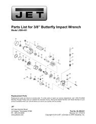
TroubleshootingThe numbers in parentheses refer to the parts breakdown on the following page.Trouble Probable Cause Remedy*Hoist will not lift (noclicking sound).Load slips or driftswhile being lowered.Hoist will not lowerload.Hoist will notfreewheel.Pawl (#21) not engaging ratchet disc(#24); possible dirt or foreign material.Pawl spring (#20) is damaged.Selector switch spring is loose ordamaged.Dirt/corrosion/foreign material in hoistcomponents.Brake is slipping. Brake seat (#23) isworn from long-term use, or isdamaged from overloading or misuse.The brake has caught. (Hoist was leftunder load condition for extendedperiod, or was shock-loaded whileoperating.)Brake components are corroded ordamaged.Brake has caught because load chainwas pulled too hard.Clean and lubricate pawl/ratchet discassemblies.Replace pawl spring.Tighten or replace selector switchspring.Inspect and correct problem. Keephoist clean and lubricated.Replace disc hub. Do not overloadhoist.Place selector lever in DOWNposition and pull hard on the leverhandle to re-set the brake. Resumeoperation.Replace components as needed;keep hoist clean and lubricated.Reset by rotating handwheelclockwise while pulling down on loadchain. Return hoist to freewheel modeand continue. Pull load chain lessforcibly.* Any disassembly or repair of the lever hoist should be performed by properly trained personnel. CallWalter Meier (Manufacturing) Inc., or go to waltermeier.com to find an authorized Service Center nearestyou.Replacement PartsReplacement parts are listed on the following pages. To order parts or reach our service department, call1-800-274-6848, Monday through Friday (see our website for business hours, www.waltermeier.com).Having the Model Number and Serial Number of your machine available when you call will allow us toserve you quickly and accurately.12
JLH Series Lever Hoists (JLH-25/50)13
Parts List: JLH-25 (0.25 Ton)Parts listed under each assembly are parts that make up that assembly.Index No. Part No. Description Size Qty1 .............. JLH25-1 ..................Top Hook Assembly ............................................................................ 1........ ...............................Top Hook ........................................................................................... 1........ ...............................Safety Latch Kit .................................................................................. 1........ ...............................Top Hook Holder ................................................................................ 12 .............. JLH25-2 ..................Safety Latch Kit .................................................................................. 2........ ...............................Safety Latch ....................................................................................... 2........ ...............................Double Spring .................................................................................... 2........ ...............................Socket Cap Screw .............................................................................. 2........ ...............................Lock Nut ............................................................................................ 23 .............. JLH25-3 ..................Top Hook Shaft .................................................................................. 14 .............. JLH25-4 ..................Bottom Hook Assembly ....................................................................... 1........ ...............................Bottom Hook ...................................................................................... 1........ ...............................Bottom Hook Holder............................................................................ 1........ ...............................Safety Latch Kit .................................................................................. 17 .............. JLH25-6 ..................Gear Cover Set .................................................................................. 18 .............. JLH25-8 ..................Reinforced Plate ................................................................................. 19 .............. JLH25-9 ..................Load Gear .......................................................................................... 210 ............ JLH25-10 ................Pinion Shaft........................................................................................ 111 ............ JLH25-11 ................Gear Side Plate .................................................................................. 112 ............ JLH25-12 ................Chain Stripper .................................................................................... 113 ............ JLH25-13 ................Stay Bolt ............................................................................................ 215 ............ JLH25-15 ................Load Sheave Assembly....................................................................... 118 ............ JLH25-18 ................Chain Guide ....................................................................................... 219 ............ JLH25-19 ................Lever Side Plate Assembly .................................................................. 1........ ...............................Lever Side Plate ................................................................................. 1........ ...............................Pawl Pin............................................................................................. 220 ............ JLH25-20 ................Pawl Spring (0.25,0.5 ton) ................................................................... 221 ............ JLH25-21 ................Pawl (0.25,0.5 ton).............................................................................. 222 ............ JLH25-22 ................Snap Ring (0.25,0.5 ton) ...................................6mm .......................... 223 ............ JLH25-23 ................Brake Seat ......................................................................................... 124 ............ JLH25-24 ................Ratchet Disc ....................................................................................... 125 ............ JLH25-25 ................Friction Disc ....................................................................................... 226 ............ JLH25-26 ................Twisting Spring ................................................................................... 127 ............ JLH25-27 ................Brake Plate ........................................................................................ 128 ............ JLH25-28 ................Bushing.............................................................................................. 129 ............ JLH25-29 ................Stop Knob .......................................................................................... 130 ............ JLH25-30 ................Brake Cover ....................................................................................... 131 ............ JLH25-31 ................Socket Head Screw and Spring Washer .............M5x42 and 5mm ......... 333 ............ JLH25-33 ................Snap Ring ........................................................9mm .......................... 134 ............ JLH25-34 ................Change Over Gear ............................................................................. 135 ............ JLH25-35 ................Lever Handle Assembly ...................................................................... 1........ ...............................Lever Handle ...................................................................................... 1........ ...............................Selector Level .................................................................................... 1........ ...............................Change Over Pawl.............................................................................. 1........ ...............................Snap Ring ........................................................6mm .......................... 1........ ...............................Roller ...............................................................Ø5mm........................ 1........ ...............................Change Over Spring ........................................................................... 114
Index No. Part No. Description Size Qty36 ............ JLH25-36 ................Snap Ring ........................................................22mm ........................ 137 ............ JLH25-37 ................Handwheel ......................................................................................... 138 ............ JLH25-38 ................Snap Ring ........................................................7mm .......................... 140 ............ JLH25-40 ................Rubber Grip ....................................................................................... 141 ............ JLH25-41 ................Bolt and Locking Nut (0.25,0.5 ton) ....................M3.5 .......................... 148 ............ JLH25-48 ................Load Chain – specify length ..............................3.2x9 mm ................... 149 ............ JLH25-49 ................End Chain Ring .................................................................................. 1Note: All parts mentioned as assembly are sold as an assembly only.When ordering replacement chain (#48), specify length.Parts List: JLH-50 (0.5 Ton)Parts listed under each assembly are parts that make up that assembly.Index No. Part No. Description Size Qty1 .............. JLH50-1 ..................Top Hook Assembly ............................................................................ 1........ ...............................Top Hook ........................................................................................... 1........ ...............................Safety Latch Kit .................................................................................. 1........ ...............................Top Hook Holder ................................................................................ 12 .............. JLH50-2 ..................Safety Latch Kit .................................................................................. 1........ ...............................Safety Latch ....................................................................................... 2........ ...............................Double Spring .................................................................................... 2........ ...............................Socket Cap Screw .............................................................................. 2........ ...............................Lock Nut ............................................................................................ 23 .............. JLH50-3 ..................Top Hook Shaft .................................................................................. 14 .............. JLH50-4 ..................Bottom Hook Assembly ....................................................................... 1........ ...............................Bottom Hook ...................................................................................... 1........ ...............................Bottom Hook Holder............................................................................ 1........ ...............................Safety Latch Kit .................................................................................. 15 .............. JLH50-5 ..................Chain Pin & Lock Nut .......................................................................... 17 .............. JLH50-7 ..................Gear Cover Set .................................................................................. 18 .............. JLH50-8 ..................Reinforced Plate ................................................................................. 19 .............. JLH50-9 ..................Load Gear .......................................................................................... 210 ............ JLH50-10 ................Pinion Shaft........................................................................................ 111 ............ JLH50-11 ................Gear Side Plate .................................................................................. 112 ............ JLH50-12 ................Chain Stripper .................................................................................... 113 ............ JLH50-13 ................Stay Bolt ............................................................................................ 214 ............ JLH50-14 ................Pin ..................................................................................................... 116 ............ JLH50-16 ................Load Sprocket .................................................................................... 117 ............ JLH50-17 ................Load Gear .......................................................................................... 118 ............ JLH50-18 ................Chain Guide ....................................................................................... 219 ............ JLH50-19 ................Lever Side Plate Assembly .................................................................. 1........ ...............................Lever Side Plate ................................................................................. 1........ ...............................Pawl Pin............................................................................................. 220 ............ JLH25-50 ................Pawl Spring (0.25,0.5 ton) ................................................................... 221 ............ JLH25-21 ................Pawl (0.25,0.5 ton).............................................................................. 215
Index No. Part No. Description Size Qty22 ............ JLH25-22 ................Snap Ring (0.25,0.5 ton) ...................................6mm .......................... 223 ............ JLH50-23 ................Brake Seat ......................................................................................... 124 ............ JLH50-24 ................Ratchet Disc ....................................................................................... 125 ............ JLH50-25 ................Friction Disc ....................................................................................... 226 ............ JLH50-26 ................Twisting Spring ................................................................................... 127 ............ JLH50-27 ................Brake Plate ........................................................................................ 128 ............ JLH50-28 ................Bushing.............................................................................................. 129 ............ JLH50-29 ................Stop Knob .......................................................................................... 130 ............ JLH50-30 ................Brake Cover ....................................................................................... 131 ............ JLH50-31 ................Socket Head Screw & Spring Washer ................M6x45 & 6mm ............ 334 ............ JLH50-34 ................Change Over Gear ............................................................................. 135 ............ JLH50-35 ................Lever Handle Assembly ...................................................................... 1........ ...............................Lever Handle ...................................................................................... 1........ ...............................Selector Lever .................................................................................... 1........ ...............................Change Over Pawl.............................................................................. 1........ ...............................Snap Ring ........................................................6mm .......................... 1........ ...............................Roller ...............................................................Ø5mm........................ 1........ ...............................Change Over Spring ........................................................................... 136 ............ JLH50-36 ................Snap Ring ........................................................25mm ........................ 137 ............ JLH50-37 ................Handwheel ......................................................................................... 138 ............ JLH50-38 ................Snap Ring ........................................................7mm .......................... 140 ............ JLH50-40 ................Rubber Grip ....................................................................................... 141 ............ JLH25-41 ................Bolt & Locking Nut (0.25, 0.5 ton) ......................M3.5 .......................... 148 ............ JLH50-48 ................Load Chain – specify length ..............................4.3x12mm .................. 149 ............ JLH50-49 ................End Chain Ring .................................................................................. 1Note: All parts mentioned as assembly are sold as an assembly only.When ordering replacement chain (#48), specify length.16