identifying natural gas leaks to the atmosphere with optical imaging
identifying natural gas leaks to the atmosphere with optical imaging
identifying natural gas leaks to the atmosphere with optical imaging

You also want an ePaper? Increase the reach of your titles
YUMPU automatically turns print PDFs into web optimized ePapers that Google loves.
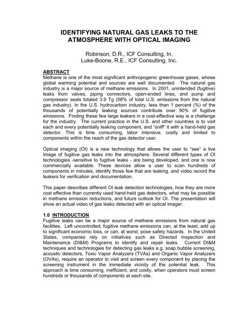
IDENTIFYING NATURAL GAS LEAKS TO THEATMOSPHERE WITH OPTICAL IMAGINGRobinson, D.R., ICF Consulting, In.Luke-Boone, R.E., ICF Consulting, Inc.ABSTRACTMethane is one of <strong>the</strong> most significant anthropogenic greenhouse <strong>gas</strong>es, whoseglobal warming potential and sources are well documented. The <strong>natural</strong> <strong>gas</strong>industry is a major source of methane emissions. In 2001, unintended (fugitive)<strong>leaks</strong> from valves, piping connec<strong>to</strong>rs, open-ended lines, and pump andcompressor seals <strong>to</strong>taled 3.9 Tg (58% of <strong>to</strong>tal U.S. emissions from <strong>the</strong> <strong>natural</strong><strong>gas</strong> industry). In <strong>the</strong> U.S. hydrocarbon industry, less than 1 percent (%) of <strong>the</strong>thousands of potentially leaking sources contribute over 90% of fugitiveemissions. Finding <strong>the</strong>se few large leakers in a cost-effective way is a challengefor <strong>the</strong> industry. The current practice in <strong>the</strong> U.S. and o<strong>the</strong>r countries is <strong>to</strong> visiteach and every potentially leaking component, and “sniff” it <strong>with</strong> a hand-held <strong>gas</strong>detec<strong>to</strong>r. This is time consuming, labor intensive, costly and limited <strong>to</strong>components <strong>with</strong>in <strong>the</strong> reach of <strong>the</strong> <strong>gas</strong> detec<strong>to</strong>r user.Optical <strong>imaging</strong> (OI) is a new technology that allows <strong>the</strong> user <strong>to</strong> “see” a liveimage of fugitive <strong>gas</strong> <strong>leaks</strong> in<strong>to</strong> <strong>the</strong> <strong>atmosphere</strong>. Several different types of OItechnologies -sensitive <strong>to</strong> fugitive <strong>leaks</strong> - are being developed, and one is nowcommercially available. These devices allow a user <strong>to</strong> scan hundreds ofcomponents in minutes, identify those few that are leaking, and video record <strong>the</strong>leakers for verification and documentation.This paper describes different OI leak detection technologies, how <strong>the</strong>y are morecost effective than currently used hand-held <strong>gas</strong> detec<strong>to</strong>rs, what may be possiblein methane emission reductions, and future outlook for OI. The presentation willshow an actual video of <strong>gas</strong> <strong>leaks</strong> detected <strong>with</strong> an <strong>optical</strong> imager.1.0 INTRODUCTIONFugitive <strong>leaks</strong> can be a major source of methane emissions from <strong>natural</strong> <strong>gas</strong>facilities. Left uncontrolled, fugitive methane emissions can, at <strong>the</strong> least, add up<strong>to</strong> significant economic loss, or can, at worst, pose safety hazards. In <strong>the</strong> UnitedStates, companies rely on initiatives such as Directed Inspection andMaintenance (DI&M) Programs <strong>to</strong> identify and repair <strong>leaks</strong>. Current DI&Mtechniques and technologies for detecting <strong>gas</strong> <strong>leaks</strong> e.g. soap bubble screening,acoustic detec<strong>to</strong>rs, Toxic Vapor Analyzers (TVAs) and Organic Vapor Analyzers(OVAs), require an opera<strong>to</strong>r <strong>to</strong> visit and screen every component by placing <strong>the</strong>screening instrument in <strong>the</strong> immediate vicinity of <strong>the</strong> potential leak. Thisapproach is time consuming, inefficient, and costly, when opera<strong>to</strong>rs must screenhundreds or thousands of components at each site.
Emerging <strong>optical</strong> <strong>imaging</strong> (OI) technologies may enable industry <strong>to</strong> reduce <strong>the</strong>time, labor and costs required <strong>to</strong> find and repair fugitive <strong>leaks</strong>. Remote sensing<strong>with</strong> OI technologies allows an opera<strong>to</strong>r <strong>to</strong> scan areas containing tens <strong>to</strong>hundreds of potential <strong>leaks</strong>, thus eliminating <strong>the</strong> need <strong>to</strong> visit and manuallymeasure all potential leak sites. Leaks are identified immediately, allowingquicker repair, and ensuring efficient use of resources. Two emerging OItechnologies have sufficient sensitivity for methane fugitive leak screening:• An infrared laser camera based on Backscatter Absorption Gas Imaging(BAGI) techniques, and• An infrared camera based on Image Multi-Spectral Sensor (IMSS)technology.2.0 BAGI CAMERAThe BAGI camera developed by SandiaNational Labora<strong>to</strong>ry is suitable for detectingmethane. It was developed <strong>to</strong> detect fugitiveemissions of most organic compounds in <strong>the</strong>petroleum and <strong>natural</strong> <strong>gas</strong> industries. Thecurrent pro<strong>to</strong>type camera weighs approximately30 lbs and is about <strong>the</strong> size of a networktelevision camera. It consists of two systems:a camera and a power/control unit (Figure 1).The camera is powered from a backpack bornepower/control (Figure 2) that is connected <strong>to</strong>ei<strong>the</strong>r a 28V lithium-ion battery or a 110-volt, 60cps AC power chord through <strong>the</strong> unit’s 28-volt DC converter. In <strong>the</strong> currentpro<strong>to</strong>type, battery lifetime whileoperational is between 1 and 1½ hours;batteries recharge in twelve hours.Batteries can be changed <strong>with</strong>out shuttingdown <strong>the</strong> camera or greatly interruptingoperations.The imager can be operated in a shouldermountedor a tripod-mounted position. Azoom lens allows <strong>the</strong> opera<strong>to</strong>r <strong>to</strong> adjust<strong>the</strong> focal distance <strong>to</strong> obtain a better view.The opera<strong>to</strong>r can switch between <strong>the</strong>infrared view and visible light, and canrecord video of <strong>the</strong> image seen in <strong>the</strong>viewfinder in both views. The camera hassimple start-up procedures requiring 10 –15 minutes after <strong>the</strong> power is switched on.Shoulder-mounted cameraBackpack power/controlFig. 1. BAGI CameraFiberlasercameraBackpack<strong>with</strong>batteriesFig. 2. Screening <strong>with</strong> <strong>the</strong> BAGICamera
2.1 BACKSCATTER ABSORPTION GAS IMAGING (BAGI)Backscatter Absorption GasImaging (BAGI) produces a livevideo image by illuminating <strong>the</strong> viewBackscatteredlaser lightarea <strong>with</strong> laser light in <strong>the</strong> infraredfrequency range. The reflected(backscattered) laser light isdetected <strong>with</strong> a camera sensitive <strong>to</strong>that light. When <strong>the</strong> chosen laserwavelength is strongly absorbed by<strong>the</strong> <strong>gas</strong> of interest, a cloud of that<strong>gas</strong> does not provide muchbackscattered light compared <strong>to</strong> itssurroundings. Because of its IR lightabsorption, <strong>the</strong> <strong>gas</strong> is revealed as adark image on <strong>the</strong> camera. Figure 3shows how BAGI works.A video camera-type scanner bothsends out <strong>the</strong> laser beam and picksup <strong>the</strong> backscattered infrared light.The camera converts thisGas PlumeIncident infraredlaser lightIncident infraredlaser lightBackscatteredlaser lightIncident infraredlaser light absorbedby chemical plumeSource: As Adapted from McRae, Tom, GasVue: A RapidLeak Location Technology for Large VOC FugitiveEmissions. (Presentation at <strong>the</strong> CSI Petroleum RefiningSec<strong>to</strong>r Equipment Leaks Group, Washing<strong>to</strong>n, DC, Sept. 9,1997). U.S. Patent # 4,555,627Note: Although <strong>gas</strong> is shown in contact <strong>with</strong> <strong>the</strong> backgroundmaterial, it is not a requirement. The <strong>gas</strong> plume need onlybe between <strong>the</strong> background and <strong>the</strong> infrared camera.Fig. 3. BAGI Principlebackscattered infrared light <strong>to</strong> an electronic signal, which is displayed in real-timeas a black and white image on <strong>the</strong> viewfinder (<strong>the</strong> camera has an auxiliary output<strong>to</strong> a video moni<strong>to</strong>r). The same image will be seen whe<strong>the</strong>r <strong>the</strong> scanning is donein daylight or at night because <strong>the</strong> scanner is only sensitive <strong>to</strong> illumination comingfrom <strong>the</strong> infrared light source, not <strong>the</strong> sun. The visible-light view is an importantattribute for <strong>the</strong> opera<strong>to</strong>r <strong>to</strong> identify <strong>the</strong> leaking component and differentiatebetween steam plumes and <strong>gas</strong> plumes (see discussion of Atmospheric Windowbelow).Figure 4 shows a leaking flange detected by <strong>the</strong> BAGI camera at a refinery inTexas, shown in visible and infrared light. In <strong>the</strong> current state of development,Visible light view of leaking flangeInfrared view of leaking flangeflangeflangehydrocarbonplumeFig. 4. Visible and Infrared Views of Leaking Flange
<strong>the</strong> technology makes visible <strong>the</strong> size of a vapor cloud of hydrocarbons that areinvisible <strong>to</strong> <strong>the</strong> naked eye, but does not quantify <strong>the</strong> mass emissions rate of <strong>the</strong>leak cloud. A detailed technical description of BAGI technology is available in [1].2.2 BAGI PERFORMANCE PARAMETERSThree main parameters influence <strong>the</strong> performance of <strong>the</strong> BAGI technology:background, laser wavelength, and atmospheric window.BACKGROUND. For <strong>the</strong> technology <strong>to</strong> image a leak, <strong>the</strong>re must be a reflective,or backscattering surface close behind <strong>the</strong> leak. It is not possible <strong>to</strong> visualize a<strong>gas</strong> plume against <strong>the</strong> sky or a distant background <strong>with</strong> BAGI. It is, however,possible in many circumstances <strong>to</strong> image a leak against <strong>the</strong> component itself,<strong>with</strong> a distant or sky background appearing dark. The opera<strong>to</strong>r knows that <strong>the</strong>imager is beyond detection range when <strong>the</strong> camera no longer produces a brightimage of <strong>the</strong> components under inspection: <strong>the</strong> more distant <strong>the</strong> component orbackground, <strong>the</strong> darker <strong>the</strong> image. The opera<strong>to</strong>r would also visually check <strong>the</strong>equipment under inspection <strong>to</strong> determine whe<strong>the</strong>r <strong>the</strong>re is an adequatebackground surface behind <strong>the</strong> potentially leaking components.LASER WAVELENGTH. Gas leak detection sensitivity by OI depends moststrongly on <strong>the</strong> match between <strong>the</strong> laser wavelength and <strong>the</strong> wavelength ofstrongest absorption by <strong>the</strong> <strong>gas</strong> of interest. To produce a dark image of a <strong>gas</strong>cloud, <strong>the</strong> hydrocarbon must be capable of absorbing <strong>the</strong> laser light at <strong>the</strong> tunedwavelength.ATMOSPHERIC WINDOW. An “atmospheric window” is defined as a region of<strong>the</strong> spectrum where <strong>the</strong>re is minimal or no light absorption by oxygen, nitrogen,carbon dioxide, and water vapor that are normally present in air. The majoratmospheric windows in <strong>the</strong> infrared region are found in <strong>the</strong> 3 <strong>to</strong> 4.2 micron andin <strong>the</strong> 8 <strong>to</strong> 13 micron wavelength regions. A laser beam propagating through <strong>the</strong><strong>atmosphere</strong> at wavelengths <strong>with</strong>in <strong>the</strong>se atmospheric windows will experienceminimal attenuation.However, laser light <strong>with</strong>in <strong>the</strong>se IR wavelength windows may still be attenuatedby particulates in <strong>the</strong> air, including water droplets as in fog and steam.Consequently, plumes of <strong>the</strong>se particulates will appear as dark clouds in <strong>the</strong>BAGI image as do <strong>the</strong> fugitive <strong>gas</strong>es that absorb <strong>the</strong> laser light. Since <strong>the</strong>separticulate plumes are also visible <strong>to</strong> <strong>the</strong> naked eye (while <strong>the</strong> fugitive <strong>gas</strong>es arenot), BAGI opera<strong>to</strong>rs can easily distinguish between <strong>the</strong> two types of cloudimages.OTHER PERFORMANCE PARAMETERS. Wind speed, <strong>gas</strong> plume motion andviewing angle affect <strong>the</strong> fugitive <strong>gas</strong> cloud, and <strong>the</strong>reby, <strong>the</strong> detection sensitivity.The higher <strong>the</strong> wind speed, <strong>the</strong> more quickly <strong>the</strong> <strong>gas</strong> is dispersed as it leaves <strong>the</strong>leak source, and <strong>the</strong> less visible it becomes <strong>to</strong> <strong>the</strong> <strong>optical</strong> imager. However,some motion is beneficial for detecting a leak, as <strong>the</strong> human eye is particularly
sensitive <strong>to</strong> movement. A stationary <strong>gas</strong> cloud is very difficult <strong>to</strong> distinguishagainst a non-uniform background.Viewing angle and <strong>optical</strong> resolution also influences detection. While <strong>the</strong> best(most sensitive) viewing angle is when <strong>the</strong> <strong>gas</strong> comes directly <strong>to</strong>wards <strong>the</strong> BAGIcamera, this is not important if <strong>the</strong> camera has sufficient <strong>optical</strong> resolution <strong>to</strong>image <strong>the</strong> <strong>gas</strong> as it exits <strong>the</strong> leaking component. Consequently, <strong>the</strong> mostfavorable leak detection conditions are <strong>to</strong> view <strong>the</strong> leak source as close aspossible, under low (but not stagnant) wind speed conditions, and <strong>with</strong> sufficientimage resolution <strong>to</strong> see <strong>the</strong> escaping <strong>gas</strong> coming directly out of <strong>the</strong> leakingcomponent. Under <strong>the</strong>se conditions, and <strong>with</strong> a fairly uniform backgroundsurface, <strong>the</strong> BAGI technology is capable of visualizing smaller <strong>leaks</strong>.3.0 The IMSS Camera.Pacific Advanced Technology (PAT)developed an infrared camera based onImage Multi-spectral Sensor (IMSS)technology. The camera, originallydeveloped for leak detection at refineriesand chemical plants, can be adapted <strong>to</strong>methane detection at <strong>natural</strong> <strong>gas</strong> facilities.The current pro<strong>to</strong>type of <strong>the</strong> IMSS camera(Figure 5) weighs 12 lb (including battery)and is 12 (L) x 6 (W) x 8 (H) inches in sizeand is battery operated. The camera,which holds a patented IMSS lens, contains<strong>the</strong> battery power source and amicroprocessor <strong>to</strong> acquire and process <strong>the</strong>hyperspectral images.Like <strong>the</strong> BAGI technology, <strong>the</strong> IMSScamera does not quantify <strong>leaks</strong>. However,unlike BAGI, it can identify chemicalspecies <strong>with</strong>in a leak. It can be used in unmannedaerial vehicles and controlled fromremote locations. It can also detectchemical species from great distances,provided <strong>the</strong>re is sufficient quantity of <strong>the</strong>chemical and a significant difference in IRradiance between <strong>the</strong> plume andbackground. In one test, <strong>the</strong> camera wasable <strong>to</strong> screen a flare on an offshore oilplatform 10 miles away and provide aspectrum showing <strong>the</strong> composition of <strong>the</strong>hot combustion <strong>gas</strong>es. Figure 6 shows <strong>the</strong>IMSS camera in use at an oil refinery.Fig. 5. The IMSS CameraFig. 6. IMSS Camera in OilRefinery
3.1 THE IMSS PRINCIPLEImage Multi-spectral Sensing is based on <strong>the</strong> principal of diffractive optics. It is acombination of a diffractive <strong>imaging</strong> spectrometer and an adaptive tunable filter.The basic concept is shown in Figure 7.A basic monochrometer has an entrance and exit slit combined <strong>with</strong> a lightdispersingmedium such as a prism. In order <strong>to</strong> obtain high resolution, <strong>the</strong>entrance and exit slits mustbe very narrow, thusreducing <strong>the</strong> <strong>optical</strong>throughput of <strong>the</strong> system.The light is dispersedperpendicular <strong>to</strong> <strong>the</strong> axis of<strong>the</strong> exit slit and is spectrallyscanned across <strong>the</strong> slit.Fig. 7. IMSS PrincipleIn <strong>the</strong> IMSS approach, a diffractive element is used <strong>to</strong> perform both <strong>imaging</strong> anddispersion of light. The diffractive <strong>optical</strong> element disperses <strong>the</strong> light along <strong>the</strong><strong>optical</strong> axis and <strong>the</strong> detec<strong>to</strong>r array/lens focal length is scanned <strong>to</strong> produceimages of different IR “colors.” The advantage of this approach is that <strong>the</strong> entireinput aperture collects <strong>the</strong> light as opposed <strong>to</strong> <strong>the</strong> narrow entrance slit and thus<strong>the</strong> throughput is greater. The detec<strong>to</strong>r element acts as <strong>the</strong> exit slit and must bematched <strong>with</strong> <strong>the</strong> blur diameter of <strong>the</strong> diffractive lens. The disadvantage of thisapproach is that micro processing must be done in order <strong>to</strong> sharpen <strong>the</strong> image ofequipment and <strong>the</strong> chemical leak spectrum. A detailed description of <strong>the</strong> processis available in reference 2.Figure 8 shows an image of a valve leaking methane at 0.1 standard cubic feetper min (scfm). The test setup is shown on <strong>the</strong> left. Gas temperature was 63.2o F, air temperature 63.7 o F. Wind was 5 <strong>to</strong> 9 mph, gusting from <strong>the</strong> left [2].Fig. 8. IMSS Images of Valve Leaking Methane4.0 FUGITIVE METHANE REDUCTION OPPORTUNITYRecent studies in <strong>the</strong> U.S. have shown that <strong>the</strong>re are significant opportunities <strong>to</strong>reduce fugitive emissions at <strong>natural</strong> <strong>gas</strong> facilities. A recent study, co-sponsored
y U.S. EPA’s Natural Gas STAR Program, showed that <strong>the</strong> methane reductionpotential using DI&M at 13 U.S. transmission stations averages 70% based on apayback period of 1 year [3]. The <strong>to</strong>tal value of <strong>gas</strong> saved by implementing <strong>the</strong>serepairs was estimated at $765K/yr (<strong>gas</strong> valued $2/Mcf).Ano<strong>the</strong>r study at <strong>gas</strong> processing facilities found <strong>the</strong> fugitive methane emissionsreduction potential at four plants about 79% based on a payback period of up <strong>to</strong>4 years for all components [4]. If <strong>gas</strong> processing plant emission reductionopportunities <strong>with</strong> payout periods between 0.5 <strong>to</strong> 4 years are considered, <strong>the</strong>study estimated percent of <strong>to</strong>tal methane savings shown in Table 1.Table 1. Payback Period For DI&M ProgramPayback Period< 6 months < 1 year < 2 years < 4 yearsMethane Emission Reduction 71.9% 78.1% 79.2% 79.5%The study of <strong>gas</strong> processing plants achieved an average $20 in gross savings($13 in net savings after repair costs) per component for leak repairs <strong>with</strong> lessthan 1-year payback based on $4.50/ Mscf <strong>gas</strong> price.OI offers significant savings in labor costs compared <strong>with</strong> conventional methodsof leak screening. Table 2 compares screening a <strong>gas</strong> processing facility <strong>with</strong>25,000 components using <strong>the</strong> current practice (TVA or OVA hand-held <strong>gas</strong>detec<strong>to</strong>r) and alternatively using <strong>optical</strong> <strong>imaging</strong>.Table 2. Comparison of Screening Gas Plant <strong>with</strong> TVA/OVA or Optical ImagingCurrent TVA/OVA Optical ImagingLeak Detec<strong>to</strong>rAverage Screening Rate 700components/day35components/minTime Required <strong>to</strong> Screen Plant 35 days 12 hrTotal Labor Cost$12,250 $300(DI&M - $0.50/component)(1 OI Technician at $25/hr)Note: time and cost <strong>to</strong> tag and repair leaking components is <strong>the</strong> same regardlessof screening method and are excluded from <strong>the</strong>se estimates. Cost of purchasingan OI camera or TVA is also excluded.5.0 FUTURE OF OPTICAL IMAGINGOI is currently used in <strong>the</strong> U.S. <strong>to</strong> identify SF 6 at power facilities and has showngreat promise for fugitive emissions control at refineries and chemical plants.Several labora<strong>to</strong>ry and field tests have been completed and negotiations are
currently underway <strong>to</strong> begin long-term testing of <strong>the</strong> BAGI technology athydrocarbon facilities. The technology offers a means <strong>to</strong> overcome cost andefficiency issues at facilities where hundreds or thousands of components are <strong>to</strong>be moni<strong>to</strong>red. An important next-step in research is a means <strong>to</strong> quantify <strong>the</strong>mass rate of detected <strong>leaks</strong>. The future of <strong>optical</strong> <strong>imaging</strong> appears promising.As <strong>with</strong> o<strong>the</strong>r video technologies, more usage and time will lead <strong>to</strong> more efficientand less expensive methane leak detection and repair.REFERENCES[1] McRae, T. G. and Kulp, T. G., “Backscatter Absorption Gas Imaging: a NewTechnique for Gas Visualization” Applied Optics, 1993, Vol. 32, 4037-4050[2] Pacific Advanced Technology, “Sherlock Gas Leak Detection Camera,” SantaYnez, CA, 2003[3] U.S. EPA Natural Gas STAR Program, PRC International, Gas ResearchInstitute, “Cost Effective Leak Mitigation at Natural Gas TransmissionCompressor Stations,” 1999[4] U.S. EPA, Gas Technology Institute, Clears<strong>to</strong>ne Engineering, Inc.“Identification And Evaluation Of Opportunities To Reduce Methane Losses AtFour Gas Processing Plants (USEPA Grant No: 827754-01-0),” Washing<strong>to</strong>n,DC, March 2000