Contents 1 Introduction 2 Operator Interface and ... - NO access
Contents 1 Introduction 2 Operator Interface and ... - NO access
Contents 1 Introduction 2 Operator Interface and ... - NO access
- No tags were found...

You also want an ePaper? Increase the reach of your titles
YUMPU automatically turns print PDFs into web optimized ePapers that Google loves.
High Power Service Manual for VLT ® FC SeriesFrequency Converters<strong>Contents</strong><strong>Contents</strong>1 <strong>Introduction</strong> 11Purpose 11VLT FC Product Overview 11For Your Safety 11Electrostatic Discharge (ESD) 12Frame Size Definitions 12Tools Required 13General Torque Tightening Values 13Exploded Views 15Ratings Tables 182 <strong>Operator</strong> <strong>Interface</strong> <strong>and</strong> Frequency Converter Control 23<strong>Introduction</strong> 23User <strong>Interface</strong> 23Numeric Local Control Panel (NLCP) 29Tips <strong>and</strong> Tricks 29Status Messages 30Service Functions 35Frequency Converter Inputs <strong>and</strong> Outputs 36Input signals 37Output signals 37Control Terminals 38Control Terminal Functions 39Earthing Screened Cables 413 Internal Frequency Converter Operation 43General 43Description of Operation 43Logic Section 44Logic to Power <strong>Interface</strong> 45Power Section 46Sequence of Operation 47Rectifier Section 47Intermediate Section 49Inverter Section 51Brake Option 53Cooling Fans 54Fan Speed Control 54Load Sharing 55MG.90.L1.02 - VLT ® is a registered Danfoss trademark 1
<strong>Contents</strong>High Power Service Manual for VLT ® FC SeriesFrequency ConvertersSpecific Card Connections 554 Troubleshooting 57Troubleshooting Tips 57Exterior Fault Troubleshooting 57Fault Symptom Troubleshooting 57Visual Inspection 59Fault Symptoms 60No Display 60Intermittent Display 60Motor Will not Run 61Incorrect Motor Operation 62Warning/Alarm Messages 63Warning/Alarm Code List 63After Repair Tests 755 Frequency Converter <strong>and</strong> Motor Applications 77Torque Limit, Current Limit, <strong>and</strong> Unstable Motor Operation 77Overvoltage Trips 78Mains Phase Loss Trips 79Control Logic Problems 79Programming Problems 80Motor/Load Problems 80Internal Frequency Converter Problems 81Overtemperature Faults 81Current Sensor Faults 81Signal <strong>and</strong> Power Wiring Considerations for Frequency Converter ElectromagneticCompatibility 82Effect of EMI 82Sources of EMI 82EMI Propagation 83Preventive Measures 85Proper EMC Installation 866 Test Procedures 87<strong>Introduction</strong> 87Tools Required for Testing 88Signal Test Board 88Test Cables 89Static Test Procedures 90Soft Charge <strong>and</strong> Rectifier Circuits Test: D-frame Size 91Soft Charge Rectifier Test: D-frame Size 932 MG.90.L1.02 - VLT ® is a registered Danfoss trademark
<strong>Contents</strong>High Power Service Manual for VLT ® FC SeriesFrequency ConvertersSCR/Diode Module D2/D4 Units 136SCR/Diode Module D1/D3 Units 140Current Sensor 143Heatsink Fan Assembly 144AC Input Terminals 146IGBT Modules D2/D4 Units 147IGBT Modules D1/D3 Units 1508 E-Frame Sizes Disassembly <strong>and</strong> Assembly Instructions 153Electrostatic Discharge (ESD) 153Instructions 153Control Card <strong>and</strong> Control Card Mounting Plate 153Control Assembly Support Bracket 154Power Card 155Soft Charge Card 156Gate Drive Card 157Capacitor Banks 158Input Terminal Mounting Plate Assy Option 160Soft Charge Resistor 161SCR <strong>and</strong> Diode Modules 162Current Sensor 165Heatsink Fan Assembly 166AC Input, Motor, Load Sharing or Regen Terminals 167IGBT Modules 1689 Special Test Equipment 173Test Equipment 173Test Cables <strong>and</strong> SCR Shorting Plug Kit p/n 176F8439 173Signal Test Board (p/n 176F8437) 174Signal Test Board Pin Outs: Description <strong>and</strong> Voltage Levels 17410 Spare Parts List 177Spare Parts List 177General Notes 177Spare Parts Lists 17811 Block Diagrams 201Block Diagrams for D-Frames 201D1/D3 380–500 VAC 201D2/D4 380–500 VAC 203D1/D3 525–690 VAC 205D2/D4 525–690 VAC 2074 MG.90.L1.02 - VLT ® is a registered Danfoss trademark
High Power Service Manual for VLT ® FC SeriesFrequency Converters<strong>Contents</strong>Block Diagrams for E-Frames 208E1/E2 380–500 VAC 208E1/E2 525–690 VAC 209MG.90.L1.02 - VLT ® is a registered Danfoss trademark 5
<strong>Contents</strong>High Power Service Manual for VLT ® FC SeriesFrequency Converters<strong>Contents</strong> | IllustrationIllustration 1.1: Exploded view D3 Frame size, D1 frame is similar. 15Illustration 1.2: Exploded view D4 frame size, D2 frame is similar. 16Illustration 1.3: Exploded view E2 frame size, E1 frame is similar. 17Illustration 2.1: Control Terminals 36Illustration 2.2: Control Terminals Electrical Diagram 40Illustration 3.1: Control Card Logic 43Illustration 3.2: Logic Section 44Illustration 3.3: Typical Power Section 46Illustration 3.4: Rectifier circuit 48Illustration 3.5: Intermediate section 50Illustration 3.6: Output Voltage <strong>and</strong> Current Waveforms 51Illustration 3.7: Inverter section 52Illustration 3.8: Brake option 53Illustration 5.1: Frequency Converter Functionality Diagram 83Illustration 5.2: Earth Currents 83Illustration 5.3: Signal Conductor Currents 84Illustration 5.4: Alternate Signal Conductor Currents 84Illustration 5.5: Proper EMC Installation 86Illustration 6.1: Signal Test Board 88Illustration 6.2: SCR Shorting Plug 89Illustration 6.3: Two-Pin 89Illustration 6.4: Three-Pin 89Illustration 6.5: Power Card, <strong>and</strong> Mounting Plate 90Illustration 6.6: Soft Charge Card Fuses 91Illustration 6.7: Soft Charge Card Connectors 94Illustration 6.8: Soft Charge Card Fuse Location 95Illustration 6.9: Soft Charge Card Connectors 97Illustration 6.10: Fan Transformer <strong>and</strong> Fuse Location 102Illustration 6.11: Fan <strong>and</strong> DC Bus Fuse Locations 104Illustration 6.12: Drive Power Terminals ( 105Illustration 6.13: Normal AC Input Voltage Waveform 110Illustration 6.14: AC Input Current Waveform with Diode Bridge 110Illustration 6.15: Input Current Waveform with Phase Loss. 111Illustration 6.16: SCR Gate Signal 112Illustration 6.17: Gate Drive Card Test Connectors 115Illustration 6.18: Gate Signal Waveform from Gate Drive Card. IGBT Gate Signal measuredon the Gate Drive Card: 5 volts per division vertical scale, 50 microseconds per division timescale. Unit running at 30 Hz. 1156 MG.90.L1.02 - VLT ® is a registered Danfoss trademark
High Power Service Manual for VLT ® FC SeriesFrequency Converters<strong>Contents</strong>Illustration 6.19: Gate Signal Waveform from Signal Test Board. IGBT Gate Signal measuredwith the Signal Test Board: 2 volts per division vertical scale, 50 microseconds per divisiontime scale. Unit running at 30 Hertz. 116Illustration 7.1: Control Card Access 124Illustration 7.1: Power Card, <strong>and</strong> Mounting Plate 125Illustration 7.1: Soft Charge Card Assy 127Illustration 7.1: Gate Drive Card 128Illustration 7.1: D2/D4 129Illustration 7.1: D1/D3 130Illustration 7.1: D2/D4 131Illustration 7.1: D2/D4 132Illustration 7.1: D1/D3 133Illustration 7.1: D1/D3 134Illustration 7.1: Input Terminal Mounting Plate Assembly (no options shown) 135Illustration 7.1: D2/D4 136Illustration 7.1: D2/D4 137Illustration 7.1: D2/D4 139Illustration 7.1: D1/D3 140Illustration 7.1: D1/D3 141Illustration 7.1: D1/D3 142Illustration 7.1: Current Sensors 143Illustration 7.1: Fan Assembly (1 of 2) 144Illustration 7.1: Fan Assembly (2 of 2) 145Illustration 7.1: AC Input Terminals (no options shown) 146Illustration 7.1: D2/D4 147Illustration 7.1: D2/D4 148Illustration 7.1: D2/D4 149Illustration 7.1: D1/D3 150Illustration 7.1: D1/D3 151Illustration 8.1: Control Card Access 154Illustration 8.1: Power Card, <strong>and</strong> Mounting Plate 155Illustration 8.1: Soft Charge Card 156Illustration 8.1: Gate Drive Card. 157Illustration 8.1: Upper <strong>and</strong> Lower Capacitor Bank Assemblies 159Illustration 8.1: Input Terminal Mounting Plate Assy (shown with RFI <strong>and</strong> mains fuse options)160Illustration 8.1: Soft Charge Resistor 161Illustration 8.1: SCR <strong>and</strong> Diode Modules (1 of 3) 162Illustration 8.1: SCR <strong>and</strong> Diode Modules (2 of 3) 163Illustration 8.1: SCR <strong>and</strong> Diode Modules (3 of 3) 164Illustration 8.1: Current Sensors 165MG.90.L1.02 - VLT ® is a registered Danfoss trademark 7
<strong>Contents</strong>High Power Service Manual for VLT ® FC SeriesFrequency ConvertersIllustration 8.1: Fan Assembly 166Illustration 8.1: Terminal Blocks 167Illustration 8.1: IGBT Modules (1 of 4) 168Illustration 8.1: IGBT Modules (2 of 4) 169Illustration 8.1: IGBT Modules (3 of 4) 170Illustration 8.1: IGBT Modules (4 of 4) 171Illustration 9.1: SCR Shorting Plug 173Illustration 9.2: Two-pin 173Illustration 9.3: Three-pin 173Illustration 9.4: Signal Test Board 1748 MG.90.L1.02 - VLT ® is a registered Danfoss trademark
High Power Service Manual for VLT ® FC SeriesFrequency Converters<strong>Contents</strong><strong>Contents</strong> | TableTable 1.1: FC 102 <strong>and</strong> FC 202 380-480 VAC 12Table 1.2: FC 302 380-500 VAC 12Table 1.3: FC 102 <strong>and</strong> FC 202 525-690 VAC 13Table 1.4: AF-600 FP 525-600 VAC 0Table 1.5: FC 302 AF-650 GP 525-690 VAC 13Table 1.6: AF-650 GP 525-690 VAC 0Table 1.7: Torque Values Table 14Table 2.1: Tips <strong>and</strong> tricks 29Table 2.2: Control Terminals <strong>and</strong> Associated Parameter 39Table 2.3: Earthing Screened Cables 41Table 3.1: IGBT Thermal Sensor 54Table 3.2: Power Card Ambient Temperature Sensor 54Table 3.3: Control Card Thermal Sensor 55Table 4.1: Visual Inspection 59Table 4.2: Warning/alarm code list 63Table 4.3: Alarm/warning code list 64Table 6.1: Fan transformer resistance 103Table 6.2: Scaling Card Resistance Values 119Table 6.3: Scaling Card Resistance ValuesAF-600 FP only up to 600 V 0Table 10.1: Spare Parts List PCA3, PCA4, PCA5, PCA8 <strong>and</strong> PCA11 178Table 10.2: Spare Parts List Semiconductors, Resistors, Capacitors <strong>and</strong> Fans 179Table 10.3: Spare Parts List Fuses, Inductors & Current Sensors <strong>and</strong> Disconnects 180Table 10.4: Spare Parts List Cables 181Table 10.5: Spare Parts List Cables 182Table 10.6: Spare parts list: Terminals, Labels, Insulators 183Table 10.7: Spare parts lists: Bus Bars (tabel 1) 184Table 10.8: Spare parts list: Bus Bars (table 2) 185Table 10.9: Spare parts list: Enclosure 186Table 10.10: Spare Parts List PCA3-11 188Table 10.11: Spare Parts List Semiconductors, Resistors, Capacitors <strong>and</strong> Fans 189Table 10.12: Spare Parts List Fuses, Inductors & Current Sensors <strong>and</strong> Disconnects 190Table 10.13: Spare Parts List Cables 191Table 10.14: Spare Parts List terminals, Labels, Insulators 192Table 10.15: Spare Parts List Bus Bars 194Table 10.16: Spare Parts List Enclosure 195Table 10.17: Spare Parts List PCA, Semiconductors <strong>and</strong> Resistors 196Table 10.18: Spare Parts List Capacitors, Fans, Fuses <strong>and</strong> Inductors & Current Sensors197Table 10.19: Spare Parts List Disconnects <strong>and</strong> Cables 198MG.90.L1.02 - VLT ® is a registered Danfoss trademark 9
<strong>Contents</strong>High Power Service Manual for VLT ® FC SeriesFrequency ConvertersTable 10.20: Spare Parts List Terminals, Labels & Insulators 199Table 10.21: Spare Parts List Bus Bars <strong>and</strong> Enclosure 20010 MG.90.L1.02 - VLT ® is a registered Danfoss trademark
High Power Service Manual for VLT ® FC SeriesFrequency Converters1 <strong>Introduction</strong>1 <strong>Introduction</strong>11.1 PurposeThe purpose of this manual is to provide detailed technical information <strong>and</strong> instructions to enablea qualified technician to identify faults <strong>and</strong> perform repairs on FC series frequency converters inthe D <strong>and</strong> E frames.It provides the reader with a general view of the unit's main assemblies <strong>and</strong> a description of theinternal processing. With this information, technicians should have a better underst<strong>and</strong>ing of thefrequency converter's operation to assist in troubleshooting <strong>and</strong> repair.This manual provides instructions for the frequency converter models <strong>and</strong> voltage ranges describedin the tables on the following page.1.2 VLT FC Product OverviewVLT HVAC FC 102 series frequency converters are designed for the HVAC markets. They operatein variable torque mode or constant torque down to 15 Hz <strong>and</strong> include special features <strong>and</strong> optionswell suited for fan <strong>and</strong> pump applications within the HVAC market.VLT ® AQUA FC 202 series frequency converters are designed for water <strong>and</strong> waste water markets.They can operate in either constant torque or variable torque with limited overload capabilities.They include specific features <strong>and</strong> options which make them well suited for use on a variety ofwater pumping <strong>and</strong> processing applications.VLT AutomationDrive series frequency converters are fully programmable for either constanttorque or variable torque industrial applications. They are full-featured frequency converters capableof operating a myriad of applications <strong>and</strong> incorporating a wide variety of control <strong>and</strong>communication options.These models are available in Chassis/IP00, NEMA 1/IP21 or NEMA 12/IP54 enclosures.1.3 For Your SafetyFrequency converters contain dangerous voltages when connected to mains. Onlya competent technician should carry out service.For dynamic test procedures, main input power is required <strong>and</strong> all devices <strong>and</strong> powersupplies connected to mains are energised at rated voltage. Use extreme cautionwhen conducting tests in a powered frequency converter. Contact with poweredcomponents could result in electrical shock <strong>and</strong> personal injury.1. DO <strong>NO</strong>T touch electrical parts of frequency converter when connected to mains. Afterdisconnecting from mains, wait 20 minutes before touching any components in D-framesize units or 40 minutes for E-frame size units. See the label on the front of the frequencyconverter door for specific discharge time.2. When repair or inspection is made, mains must be disconnected.MG.90.L1.02 - VLT ® is a registered Danfoss trademark 11
1 <strong>Introduction</strong>High Power Service Manual for VLT ® FC SeriesFrequency Converters13. The STOP key on the control panel does not disconnect mains.4. During operation <strong>and</strong> while programming parameters, the motor may start withoutwarning. Activate the STOP key when changing data.When performing service, use proper ESD procedures to prevent damage to sensitivecomponents.1.4 Electrostatic Discharge (ESD)Many electronic components within the frequency converter are sensitive to static electricity. Voltagesso low that they cannot be felt, seen or heard can reduce the life, affect performance, orcompletely destroy sensitive electronic components.1.5 Frame Size Definitions380-480 VAC PowerModel FC 102Drive <strong>and</strong> FC-202 VLTAQUA DrivekW @400 VAC HP @460 VAC Frame SizeP110 110 150 D1 / D3P132 132 200 D1 / D3P160 160 250 D2 / D4P200 200 300 D2 / D4P250 250 350 D2 / D4P315 315 450 E1 / E2P355 355 500 E1 / E2P400 400 550 E1 / E2P450 450 600 E1 / E2Table 1.1: FC 102 <strong>and</strong> FC 202 380-480 VAC380-500 VAC PowerModel FC 302 High / Normal OverloadkW @400 VAC HP @460 VAC kW @500 VAC Frame SizeP90K 90 / 110 125 / 150 110 / 132 D1 / D3P110 110 / 132 150 / 200 132 / 160 D1 / D3P132 132 / 160 200 / 250 160 / 200 D2 / D4P160 160 / 200 250 / 300 200 / 250 D2 / D4P200 200 / 250 300 / 350 250 / 315 D2 / D4P250 250 / 315 350 / 450 315 / 355 E1 / E2P315 315 / 355 450 / 500 355 / 400 E1 / E2P355 355 / 400 500 / 550 400 / 500 E1 / E2P400 400 / 450 550 / 600 500 / 530 E1 / E2Table 1.2: FC 302 380-500 VAC12 MG.90.L1.02 - VLT ® is a registered Danfoss trademark
1 <strong>Introduction</strong>High Power Service Manual for VLT ® FC SeriesFrequency Converters11.7 General Torque Tightening ValuesFor fastening hardware described in this manual, the torque values in the table below are used.These values are not intended for SCR, diode, or IGBT fasteners. See the instructions includedwith those replacement parts for correct values.Shaft Size Driver Size Torx / Hex Torque (in-lbs) Torque (Nm)M4 T-20 / 7 mm 10 1.0M5 T-25 / 8 mm 20 2.3M6 T-30 / 10 mm 35 4.0M8 T-40 / 13 mm 85 9.6M10 T-50 / 17 mm 170 19.2Table 1.7: Torque Values Table14 MG.90.L1.02 - VLT ® is a registered Danfoss trademark
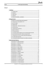
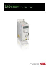
High Power Service Manual for VLT ® FC SeriesFrequency Converters1 <strong>Introduction</strong>1.8 Exploded Views121345672524891023112221201913121814171516130BX167.10Illustration 1.1: Exploded view D3 Frame size, D1 frame is similar.1 Control card PCA1 14 SCR/Diode module SCR 1, 2, 32 Control input terminals 15 IGBT output bus bar3 Local Control Panel LCP 16 Output motor terminals TB24 Control card C option 17 Current sensor L2, L3, L45 Mounting bracket 18 Fan assembly F1 + C1 +CBL116 Power card mounting plate 19 Fan transformer TR17 Power card PCA 3 20 Main AC power input terminals TB18 Capacitor bank assembly CBANK1 + PCA9 21 AC input bus bar9 Soft charge fuses 22 Input terminal mounting plate assembly10 Soft charge card PCA11 23 Fan fuse FU411 DC inductor L1 24 Capacitor bank cover plate12 Soft charge module R1 + CBL26 25 IGBT gate drive card PCA513 IGBT module IGBT 1MG.90.L1.02 - VLT ® is a registered Danfoss trademark 15
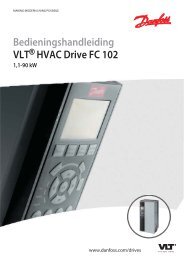
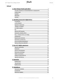
High Power Service Manual for VLT ® FC SeriesFrequency Converters1 <strong>Introduction</strong>123415672589212223241011122013141615130BX168.1019 1817Illustration 1.3: Exploded view E2 frame size, E1 frame is similar.1 Control card PCA1 14 SCR <strong>and</strong> Diode SCR1, SCR2, SCR3 <strong>and</strong> D1, D2, D32 Control input terminals 15 Fan inductor (not on all units)3 Local Control Panel LCP 16 Soft charge resistor assy R14 Control card C option 17 IGBT output bus bar5 Mounting bracket 18 Fan assembly F1 + C16 Power card mounting plate 19 Output motor terminals TB27 Power card PCA3 20 Current sensor L2, L3, L48 IGBT gate drive card PCA5 21 Main AC power input terminals TB19 Upper capacitor bank assembly CBANK2 + PCA11 22 Input terminal mounting plate assembly10 Soft charge fuses 23 AC input bus bar11 DC inductor L1 24 Soft charge card PCA1212 Fan transformer TR1 25 Lower capacitor bank assembly CBANK1 + PCA1013 IGBT module IGBT1, 2, 3MG.90.L1.02 - VLT ® is a registered Danfoss trademark 17
1 <strong>Introduction</strong>High Power Service Manual for VLT ® FC SeriesFrequency Converters11.9 Ratings TablesDC Voltage Levels380–480 <strong>and</strong> 380–500 units 525–690 unitsInrush Circuit Enabled 370 VDC 548 VDCInrush Circuit Disabled 395 VDC 600 VDCInverter Undervoltage Disable 402 VDC 553 VDCUndervoltage Warning 423 VDC 585 VDCInverter Undervoltage Re-Enable (warning reset)442 VDC 602 VDCOvervoltage Warning (without brake) 817 VDC 1084 VDCDynamic Brake Turn On 810 VDC 1099 VDCInverter Overvoltage Re-Enable (warning reset)821 VDC 1099 VDCOvervoltage Warning (with brake) 828 VDC 1109 VDCOvervoltage Trip 855 VDC 1130 VDCMains supply 3 x 380–480/500 VModel number FC102/202 P110 P132 P160 P200 P250FC302 P90K P110 P132 P160 P200Normal overload current ratings (110%):Output current Nominal [A] (380–440 V) 212 260 315 395 480MAX (60 sec) [A] (380–440V) 233 286 347 434 528Nominal [A] (441–500 V) 190 240 302 361 443MAX (60 sec) [A] (441–500V) 209 264 332 397 487Output Nominal [kVA] (400 V) 147 180 218 274 333Nominal [kVA] (460 V) 151 191 241 288 353Nominal [kVA] (500 V) 165 208 262 313 384Typical shaft output [kW] (400 V) 110 132 160 200 250[HP] (460 V) 150 200 250 300 350[kW] (500 V) 132 160 200 250 315High overload torque (160%):Output current Nominal [A] (380–440 V) 177 212 260 315 395MAX (60 sec) [A] (380–440V) 266 318 390 473 593Nominal [A] (441–500 V) 160 190 240 302 361MAX (60 sec) [A] (441–500V) 240 285 360 453 542Output Nominal [kVA] (400 V) 123 147 180 218 274Nominal [kVA] (460 V) 127 151 191 241 288Nominal [kVA] (500 V) 139 165 208 262 313Typical shaft output [kW] (400 V) 90 110 132 160 200[HP] (460 V) 125 150 200 250 300[kW] (500 V) 110 132 160 200 250Power loss Normal overload [W] 3234 3782 4213 5117 5893Power loss High overload [W] 2641 2995 3425 3910 4625Limits <strong>and</strong> RangesOvercurrent Warning VLT A RMS Out 329 394 484 586 735Overcurrent Alarm (1.5 sec delay) VLT A RMS Out 329 394 484 586 735Earth (Ground) Fault Alarm VLT A RMS Out 80 95 120 151 180Short Circuit Alarm VLT A RMS Out 420 502 616 747 936Heatsink Overtemperature Degrees C 85 90 105 105 115Heatsink Undertemperature Warning Degrees C 0 0 0 0 0Power Card Ambient Overtemperature Degrees C 60 60 60 60 60Power Card Ambient Undertemperature Degrees C -20 -20 -20 -20 -20Mains Phase Warning (5 sec delay) DC Bus Ripple VAC 50 50 50 50 50Mains Phase Alarm (25 sec delay) DC Bus Ripple VAC 50 50 50 50 5018 MG.90.L1.02 - VLT ® is a registered Danfoss trademark
High Power Service Manual for VLT ® FC SeriesFrequency Converters1 <strong>Introduction</strong>Mains supply 3 x 380–480/500 VModel number FC102/202 P315 P355 P400 P450FC302 P250 P315 P355 P400Normal overload current ratings (110%):Output current Nominal [A] (380–440 V) 600 658 745 800MAX (60 sec) [A] (380–440 V) 660 724 820 880Nominal [A] (441–500 V) 540 590 678 730MAX (60 sec) [A] (441–500 V) 594 649 746 8031Output Nominal [kVA] (400 V) 416 456 516 554Nominal [kVA] (460 V) 430 470 540 582Nominal [kVA] (500 V) 468 511 587 632Typical shaft output [kW] (400 V) 315 355 400 450[HP] (460 V) 450 500 550/600 600[kW] (500 V) 355 400 500 530High overload torque (160%):Output current Nominal [A] (380–440 V) 480 600 658 695MAX (60 sec) [A] (380–440 V) 720 900 987 1043Nominal [A] (441–500 V) 443 540 590 678MAX (60 sec) [A] (441–500 V) 665 810 885 1017Output Nominal [kVA] (400 V) 333 416 456 482Nominal [kVA] (460 V) 353 430 470 540Nominal [kVA] (500 V) 384 468 511 587Typical shaft output [kW] (400 V) 250 315 355 400[HP] (460 V) 350 450 500 550[kW] (500 V) 315 355 400 500Power loss Normal overload [W] 6790 7701 8879 9670Power loss High overload [W] 5165 6960 7691 8636Limits <strong>and</strong> RangesOvercurrent Warning VLT A RMS Out 893 1169 1169 1301Overcurrent Alarm (1.5 sec delay) VLT A RMS Out 893 1169 1169 1301Earth (Ground) Fault Alarm VLT A RMS Out 265 322 352 405Short Circuit Alarm VLT A RMS Out 1138 1490 1490 1654Heatsink Overtemperature Degrees C 95 95 95 95Heatsink Undertemperature Warning Degrees C 0 0 0 0Power Card Ambient Overtemperature Degrees C 68 68 68 68Power Card Ambient Undertemperature Degrees C -20 -20 -20 -20Mains Phase Warning (5 sec delay) DC Bus Ripple VAC 70 70 70 70Mains Phase Alarm (25 sec delay) DC Bus Ripple VAC 70 70 70 70MG.90.L1.02 - VLT ® is a registered Danfoss trademark 19
1 <strong>Introduction</strong>High Power Service Manual for VLT ® FC SeriesFrequency Converters1Mains supply 3 x 525–690 VModel numberFC102/202P25 P31 P40P132 P160 P200 0 5 0FC302P20 P25 P31P110 P132 P160 0 0 5Normal overload current ratings (110%):Output current Nominal [A] (525–550 V) 162 204 253 303 360 418MAX (60 sec) [A] (525–550 V) 178 224 278 333 396 460Nominal [A] (551–690 V) 155 192 242 290 344 400MAX (60 sec) [A] (551–690 V) 171 211 266 319 378 440Output Nominal [kVA] (550 V) 154 194 241 289 343 398Nominal [kVA] (575 V) 154 191 241 289 343 398Nominal [kVA] (690 V) 185 229 289 347 411 478Typical shaft output [kW] (550 V) 110 132 160 200 250 315[HP] (575 V) 150 200 250 300 350 400[kW] (690 V) 132 160 200 250 315 400High overload torque (160%):Output current Nominal [A] (525–550 V) 137 162 204 253 303 360MAX (60 sec) [A] (525–550 V) 206 243 306 380 455 540Nominal [A] (551–690 V) 131 155 192 242 290 344MAX (60 sec) [A] (551–690 V) 197 233 288 363 435 516Output Nominal [kVA] (550 V) 131 154 194 241 289 343Nominal [kVA] (575 V) 130 154 191 241 289 343Nominal [kVA] (690 V) 157 185 229 289 347 411Typical shaft output [kW] (550 V) 90 110 132 160 200 250[HP] (575 V) 125 150 200 250 300 350[kW] (690 V) 110 132 160 200 250 315Power loss Normal overload [W] 3114 3612 4293Power loss High overload [W] 2665 2953 3451515542755821487561495185Limits <strong>and</strong> RangesOvercurrent Warning VLT A RMS Out 256 329 483 483 585 734Overcurrent Alarm (1.5 secdelay) VLT A RMS Out 256 329 483 483 585 734Earth (Ground) Fault Alarm VLT A RMS Out 66 78 96 121 145 172Short Circuit Alarm VLT A RMS Out 325 420 614 614 742 932Heatsink Overtemperature Degrees C 85 90 110 110 110 110Heatsink UndertemperatureWarning Degrees C 0 0 0 0 0 0Power Card Ambient OvertemperatureDegrees C 60 60 60 60 60 60Power Card Ambient UndertemperatureDegrees C -20 -20 -20 -20 -20 -20Mains Phase Warning (5 secdelay) DC Bus Ripple VAC 70 70 70 70 70 70Mains Phase Alarm (25 sec delay)DC Bus Ripple VAC 70 70 70 70 70 7020 MG.90.L1.02 - VLT ® is a registered Danfoss trademark
High Power Service Manual for VLT ® FC SeriesFrequency Converters1 <strong>Introduction</strong>Mains supply 3 x 525–690 VModel number FC102/202 P45K P55K P75K P90K P110KFC302 P37K P45K P55K P75K P90KNormal overload current ratings (110%):Output current Nominal [A] (525–550 V) 56 76 90 113 137MAX (60 sec) [A] (525–550 V) 62 84 99 124 151Nominal [A] (551–690 V) 54 73 86 108 131MAX (60 sec) [A] (551–690 V) 59 80 95 119 1441Output Nominal [kVA] (550 V) 53 72 86 108 131Nominal [kVA] (575 V) 54 73 86 108 130Nominal [kVA] (690 V) 65 87 103 129 157Typical shaft output [kW] (550 V) 37 45 55 75 90[HP] (575 V) 50 60 75 100 125[kW] (690 V) 45 55 75 90 110High overload torque (160%):Output current Nominal [A] (525–550 V) 48 56 76 90 113MAX (60 sec) [A] (525–550 V) 77 90 122 135 170Nominal [A] (551–690 V) 46 54 73 86 108MAX (60 sec) [A] (551–690 V) 74 86 117 129 162Output Nominal [kVA] (550 V) 46 53 72 86 108Nominal [kVA] (575 V) 46 54 73 86 108Nominal [kVA] (690 V) 55 65 87 103 129Typical shaft output [kW] (550 V) 30 37 45 55 75[HP] (575 V) 40 50 60 75 100[kW] (690 V) 37 45 55 75 90Power loss Normal overload [W] 1458 1717 1913 2262 2662Power loss High overload [W] 1355 1459 1721 1913 2264Limits <strong>and</strong> RangesOvercurrent Warning VLT A RMS Out 256 256 256 256 256Overcurrent Alarm (1.5 sec delay) VLT A RMS Out 256 256 256 256 256Earth (Ground) Fault Alarm VLT A RMS Out 23 27 37 43 54Short Circuit Alarm VLT ARMS Out 325 325 325 325 325Heatsink Overtemperature Degrees C 85 85 85 85 85Heatsink Undertemperature Warning Degrees C 0 0 0 0 0Power Card Ambient Overtemperature Degrees C 60 60 60 60 60Power Card Ambient Overtemperature Degrees C -20 -20 -20 -20 -20Mains Phase Warning (5 sec delay) DC Bus Ripple VAC 70 70 70 70 70Mains Phase Alarm (25 sec delay) DC Bus Ripple VAC 70 70 70 70 70MG.90.L1.02 - VLT ® is a registered Danfoss trademark 21
1 <strong>Introduction</strong>High Power Service Manual for VLT ® FC SeriesFrequency Converters1Mains supply 3 x 525–690 VModel number FC102/202 P450 P500 P560 P630FC302 P355 P400 P500 P560Normal overload current ratings (110%):Output current Nominal [A] (525–550 V) 470 523 596 630MAX (60 sec) [A] (525–550 V) 517 575 656 693Nominal [A] (551–690 V) 450 500 570 630MAX (60 sec) [A] (551–690 V) 495 550 627 693Output Nominal [kVA] (550 V) 448 498 568 600Nominal [kVA] (575 V) 448 498 568 627Nominal [kVA] (690 V) 538 598 681 753Typical shaft output [kW] (550 V) 355 400 450 500[HP] (575 V) 450 500 600 650[kW] (690 V) 450 500 560 630High overload torque (160%):Output current Nominal [A] (525–550 V) 395 429 523 596MAX (60 sec) [A] (525–550 V) 593 644 785 894Nominal [A] (551–690 V) 380 410 500 570MAX (60 sec) [A] (551–690 V) 570 615 750 855Output Nominal [kVA] (550 V) 376 409 498 568Nominal [kVA] (575 V) 376 408 498 568Nominal [kVA] (690 V) 454 490 598 681Typical shaft output [kW] (550 V) 315 315 400 450[HP] (575 V) 400 400 500 600[kW] (690 V) 355 400 500 560Power loss Normal overload [W] 6449 7249 8727 9673Power loss High overload [W] 5383 5818 7671 8715Limits <strong>and</strong> RangesOvercurrent Warning VLT A RMS Out 824 824 989 1168Overcurrent Alarm (1.5 sec delay) VLT A RMS Out 824 824 989 1168Earth (Ground) Fault Alarm VLT A RMS Out 190 205 250 285Short Circuit Alarm VLT A RMS Out 1046 1046 1255 1490Heatsink Overtemperature Degrees C 85 85 85 85Heatsink Undertemperature Warning Degrees C 0 0 0 0Power Card Ambient Overtemperature Degrees C 68 68 68 68Power Card Ambient Undertemperature Degrees C -20 -20 -20 -20Mains Phase Warning (5 sec delay) DC Bus Ripple VAC 70 70 70 70Mains Phase Alarm (25 sec delay) DC Bus Ripple VAC 70 70 70 7022 MG.90.L1.02 - VLT ® is a registered Danfoss trademark
High Power Service Manual for VLT ® FC SeriesFrequency Converters2 <strong>Operator</strong> <strong>Interface</strong> <strong>and</strong> Frequency ConverterControl2 <strong>Operator</strong> <strong>Interface</strong> <strong>and</strong> Frequency ConverterControl2.1 <strong>Introduction</strong>2Frequency converters are designed with self-diagnostic circuitry to isolate fault conditions <strong>and</strong>activate display messages which greatly simplify troubleshooting <strong>and</strong> service. The operating statusof the frequency converter is displayed in real-time. Virtually every comm<strong>and</strong> given to the frequencyconverter results in some indication on the local control panel LCP display. Fault logs aremaintained within the frequency converter for fault history.The frequency converter monitors supply <strong>and</strong> output voltages along with the operational conditionof the motor <strong>and</strong> load. When the frequency converter issues a warning or alarm, it cannot beassumed that the fault lies within the frequency converter itself. In fact, for most service calls, thefault condition will be found outside of the frequency converter. Most of the warnings <strong>and</strong> alarmsthat the frequency converter displays are generated by response to faults outside of the frequencyconverter. This service manual provides techniques <strong>and</strong> test procedures to help isolate a faultcondition whether in the frequency converter or elsewhere.Familiarity with the information provided on the display is important. Additional diagnostic datacan be <strong>access</strong>ed easily through the LCP.2.2 User <strong>Interface</strong>2.2.1 How to Operate the Graphic Local Control Panel (LCP)The LCP is divided into four functional groups:1. Graphical display with status lines.2. Menu keys <strong>and</strong> indicator lights (LEDs) - selecting mode, changing parameters <strong>and</strong>switching between display functions.3. Navigation keys <strong>and</strong> indicator lights (LEDs).4. Operation keys <strong>and</strong> indicator lights (LEDs).Graphical display:The LCD display is back lit with a total of 6 alpha-numeric lines. All data is displayed on the LCPwhich can show up to five operating variables whilst in [Status] mode.MG.90.L1.02 - VLT ® is a registered Danfoss trademark 23
2 <strong>Operator</strong> <strong>Interface</strong> <strong>and</strong> Frequency ConverterControlHigh Power Service Manual for VLT ® FC SeriesFrequency ConvertersDisplay lines:2a. Status line: Status messages displayingicons <strong>and</strong> graphics.b. Line 1-2: <strong>Operator</strong> data lines displayingdata <strong>and</strong> variables defined orchosen by the user. By pressing the[Status] key, up to one extra line canbe added.c. Status line: Status messages displayingtext.The display is divided into three sections:Top section (a) shows the status when in status mode or up to two variables when not in statusmode <strong>and</strong> in the case of Alarm/Warning.The number of the Active Set-up (selected as the Active Set-up in par. 0-10 Active Set-up) isshown. When programming in another Set-up than the Active Set-up, the number of the Set-upbeing programmed appears to the right in brackets.The Middle section (b) shows up to 5 variables with related unit, regardless of status. In caseof alarm/warning, the warning is shown instead of the variables.It is possible to toggle between three status readout displays by pressing the [Status] key.Operating variables with different formatting are shown in each status screen - see below.Several values or measurements can be linked to each of the displayed operating variables. Thevalues/measurements to be displayed can be defined via par. 0-20, 0-21, 0-22, 0-23, <strong>and</strong> 0-24,which can be <strong>access</strong>ed via [QUICK MENU] Q3 Function Setups, Q3-1 General Settings, Q3-13Display Settings.Each value/measurement readout parameter selected in par. 0-20 Display Line 1.1 Small to par.0-24 Display Line 3 Large has its own scale <strong>and</strong> number of digits after a possible decimal point.Larger numeric values are displayed with few digits after the decimal point.Ex.: Current readout5.25 A; 15.2 A 105 A.24 MG.90.L1.02 - VLT ® is a registered Danfoss trademark
High Power Service Manual for VLT ® FC SeriesFrequency Converters2 <strong>Operator</strong> <strong>Interface</strong> <strong>and</strong> Frequency ConverterControlStatus display I:This readout state is st<strong>and</strong>ard after start-up orinitialisation.Use [INFO] to obtain information about thevalue/measurement linked to the displayedoperating variables (1.1, 1.2, 1.3, 2, <strong>and</strong> 3).See the operating variables shown in the displayin this illustration. 1.1, 1.2 <strong>and</strong> 1.3 areshown in small size. 2 <strong>and</strong> 3 are shown in mediumsize.1.11.2231.3130BP041.102Status display II:See the operating variables (1.1, 1.2, 1.3, <strong>and</strong>2) shown in the display in this illustration.In the example, Speed, Motor current, Motorpower <strong>and</strong> Frequency are selected as variablesin the first <strong>and</strong> second lines.1.1, 1.2 <strong>and</strong> 1.3 are shown in small size. 2 isshown in large size.1.1130BP062.1021.31.2Status display III:This state displays the event <strong>and</strong> action of theSmart Logic Control.130BP063.10The Bottom section always shows the stateof the frequency converter in Status mode.Display contrast adjustmentTop sectionMiddle section130BP074.10Press [status] <strong>and</strong> [▲] for darker displayBottom sectionPress [status] <strong>and</strong> [▼] for brighter displayMG.90.L1.02 - VLT ® is a registered Danfoss trademark 25
2 <strong>Operator</strong> <strong>Interface</strong> <strong>and</strong> Frequency ConverterControlHigh Power Service Manual for VLT ® FC SeriesFrequency ConvertersIndicator lights (LEDs):2If certain threshold values are exceeded, the alarm <strong>and</strong>/or warning LED lights up. A status <strong>and</strong>alarm text appears on the control panel.The On indicator lamp is activated when the frequency converter receives power from mains voltage,a DC bus terminal, or an external 24 V supply. At the same time, the back light is on.• Green LED/On: Control section isworking.• Yellow LED/Warn.: Indicates a warning.• Flashing Red LED/Alarm: Indicatesan alarm.LCP keysMenu keysThe menu keys are divided into functions. Thekeys below the display <strong>and</strong> indicator lamps areused for parameter set-up, including choice ofdisplay indication during normal operation.130BP045.10[Status]indicates the status of the frequency converter <strong>and</strong>/or the motor. Three different readouts can bechosen by pressing the [Status] key:5 line readouts, 4 line readouts or Smart Logic Control.Use [Status] for selecting the mode of display or for changing back to Display mode from eitherthe Quick Menu mode, the Main Menu mode or Alarm mode. Also use the [Status] key to togglesingle or double readout mode.[Quick Menu]allows quick set-up of the frequency converter. The most common functions can be programmedhere.The [Quick Menu] consists of:- My Personal Menu- Quick Set-up- Function set-up- Changes Made- LoggingsThe Function set-up provides quick <strong>and</strong> easy <strong>access</strong> to all parameters required for the majority ofapplications. Among other features it also includes parameters for selecting which variables todisplay on the LCP.26 MG.90.L1.02 - VLT ® is a registered Danfoss trademark
High Power Service Manual for VLT ® FC SeriesFrequency Converters2 <strong>Operator</strong> <strong>Interface</strong> <strong>and</strong> Frequency ConverterControl[Main Menu]is used for programming all parameters. The Main Menu parameters can be <strong>access</strong>ed immediatelyunless a password has been created via par. 0-60, 0-61, 0-65 or 0-66.Parameter shortcut can be carried out by pressing down the [Main Menu] key for 3 seconds.The parameter shortcut allows direct <strong>access</strong> to any parameter.[Alarm Log]displays an Alarm list of the five latest alarms (numbered A1-A5). To obtain additional details aboutan alarm, use the arrow keys to find the alarm number <strong>and</strong> press [OK]. Information is displayedabout the condition of the frequency converter before it enters the alarm mode.2The [Alarm log] button on the LCP allows <strong>access</strong> to both the Alarm log <strong>and</strong> Maintenance log.[Back]reverts to the previous step or layer in the navigation structure.[Cancel]last change or comm<strong>and</strong> will be cancelled as long as the display has not been changed.[Info]displays information about a comm<strong>and</strong>, parameter, or function in any display window. [Info] providesdetailed information when needed.Exit Info mode by pressing either [Info], [Back], or [Cancel].Navigation keysThe four navigation arrows are used to navigatebetween the different choices availablein [Quick Menu], [Main Menu] <strong>and</strong>[Alarm Log]. Use the keys to move the cursor.[OK] is used for choosing a parametermarked by the cursor <strong>and</strong> for enabling thechange of a parameter.Operation keys for local control are found atthe bottom of the control panel.130BP046.10MG.90.L1.02 - VLT ® is a registered Danfoss trademark 27
2 <strong>Operator</strong> <strong>Interface</strong> <strong>and</strong> Frequency ConverterControlHigh Power Service Manual for VLT ® FC SeriesFrequency Converters2[H<strong>and</strong> On]Enables control of the frequency converter via the LCP. [H<strong>and</strong> On] also starts the motor, <strong>and</strong> it isnow possible to enter the motor speed data by means of the arrow keys. The key can be selectedas Enable [1] or Disable [0] via par. 0-40 [H<strong>and</strong> on] Key on LCP.The following control signals will still be active when [H<strong>and</strong> On] is activated:• [H<strong>and</strong> On] - [Off] - [Auto On]• Reset• Coasting stop inverse• Reversing• Set-up select lsb - Set-up select msb• Stop comm<strong>and</strong> from serial communication• Quick stop• DC brakeNB!External stop signals activated by means of control signals or a serial bus will overridea start comm<strong>and</strong> via the LCP.[Off]stops the connected motor. The key can be selected as Enable [1] or Disable [0] via par.0-41 [Off] Key on LCP. If no external stop function is selected <strong>and</strong> the [Off] key is inactive, themotor can only be stopped by disconnecting the mains supply.[Auto On]enables the frequency converter to be controlled via the control terminals <strong>and</strong>/or serial communication.When a start signal is applied on the control terminals <strong>and</strong>/or the bus, the frequencyconverter will start. The key can be selected as Enable [1] or Disable [0] via par. 0-42 [Auto on]Key on LCP.NB!An active HAND-OFF-AUTO signal via the digital inputs has higher priority than thecontrol keys [H<strong>and</strong> On] – [Auto On].[Reset]is used for resetting the frequency converter after an alarm (trip). It can be selected as Enable[1] or Disable [0] via par. 0-43 [Reset] Key on LCP.The parameter shortcut can be carried out by holding down the [Main Menu] key for 3 seconds.The parameter shortcut allows direct <strong>access</strong> to any parameter.28 MG.90.L1.02 - VLT ® is a registered Danfoss trademark
High Power Service Manual for VLT ® FC SeriesFrequency Converters2 <strong>Operator</strong> <strong>Interface</strong> <strong>and</strong> Frequency ConverterControl2.2.2 Numeric Local Control Panel (NLCP)See the FC Series Operating Instructions for instructions for using the numeric LCP.2.2.3 Tips <strong>and</strong> Tricks2* For the majority of applications the Quick Menu, Quick Set-up <strong>and</strong> Function Set-up provides the simplest<strong>and</strong> quickest <strong>access</strong> to all the typical parameters required.* Whenever possible, performing an AMA will ensure best shaft performance.*Display contrast can be adjusted by pressing [Status] <strong>and</strong> [▲] for a darker display or by pressing [Status]<strong>and</strong> [▼] for a brighter display.* Under [Quick Menu] <strong>and</strong> [Changes Made], any parameter that has been changed from factory settingsis displayed.* Press <strong>and</strong> hold the [Main Menu] key for 3 seconds to <strong>access</strong> any parameter* For service purposes, it is recommended to copy all of the parameters to the LCP, see par. 0-50 LCPCopy for further information.Table 2.1: Tips <strong>and</strong> tricksMG.90.L1.02 - VLT ® is a registered Danfoss trademark 29
2 <strong>Operator</strong> <strong>Interface</strong> <strong>and</strong> Frequency ConverterControlHigh Power Service Manual for VLT ® FC SeriesFrequency Converters22.3 Status MessagesStatus messages appear in the bottom of the display - see the example below.The left part of the status line indicates the active operation model of the frequency converter.The centre part of the status line indicates the references site.The last part of the status line gives the operation status, e.g. Running, Stop or St<strong>and</strong> by.Other status messages may appear related to the software version <strong>and</strong> frequency converter type.Operation Mode130BP046.10[Off] The FC does not react to any control signal until [Auto On] or [H<strong>and</strong> On] on the LCP arepressed.[Auto On] The FC is controlled via the control terminals <strong>and</strong>/or the serial communication.[H<strong>and</strong> On] Only stop comm<strong>and</strong>s, alarm resets (Reset), reversing, DC brake, <strong>and</strong> set-up selectionsignals can be applied to the control terminals.For further information about the LCD display, please see the chapter How to programme in theProgramming Guide.30 MG.90.L1.02 - VLT ® is a registered Danfoss trademark
High Power Service Manual for VLT ® FC SeriesFrequency Converters2 <strong>Operator</strong> <strong>Interface</strong> <strong>and</strong> Frequency ConverterControlReference Site[Remote] The Reference is given via internal preset references (absolute or relative) <strong>and</strong>/or externalsignals (analog or digital) <strong>and</strong>/or via serial communication.[Local] The FC uses the reference values set via the LCP.For further information, please examine parameter 3-13.Operation StatusAC BrakeAC Brake was selected in par. 2-10 Brake Function. The motor is slowed down via the active downramp <strong>and</strong> feeds the FC with generative energy. The AC Brake over-magnetizes the motor to achievea controlled end of the active ramp.AMA finish OKEnable complete or reduced AMA was selected in par. 1-29 Automatic Motor Adaptation (AMA).The Automatic Motor Adaptation was carried out successfully.AMA readyEnable complete or reduced AMA was selected in par. 1-29 Automatic Motor Adaptation (AMA).The Automatic Motor Adaptation is ready to start. Press [H<strong>and</strong> On] on the LCP to start.AMA runningEnable complete or reduced AMA was selected in par. 1-29 Automatic Motor Adaptation (AMA).The AMA process is in progress.BrakingThe brake chopper is in operation. Generative energy is absorbed by the brake resistor.Braking max.The brake chopper is in operation. The power limit for the brake resistor defined in par.2-12 Brake Power Limit (kW) is reached.Bus Jog 1PROFIDrive profile was selected in par. 8-10 Control Word Profile. The Jog 1 function is activatedvia serial communication. The motor is running with par. 8-90 Bus Jog 1 Speed.Bus Jog 2PROFIDrive profile was selected in par. 8-10 Control Word Profile. The Jog 2 function is activatedvia serial communication. The motor is running with par. 8-91 Bus Jog 2 Speed.Catch upThe output frequency is corrected by the value set in par. 3-12 Catch up/slow Down Value.1. Catch up is selected as a function for a digital input (parameter group 5-1*). The correspondingterminal is active.2. Catch up was activated via serial communication.Coast1. Coast inverse has been selected as a function for a digital input (parameter group 5-1*).The corresponding terminal (e.g. Terminal 27) is not connected.2. Coast is on 0 on serial communicationControl readyPROFIDrive profile was selected in par. 8-10 Control Word Profile. The FC needs the second part(e.g. 0x047F) of the two-part start comm<strong>and</strong> via serial communication to allow starting. Using aterminal is not possible.Ctrl. Ramp-downA function with Ctrl. Ramp-down was selected in par. 14-10 Mains Failure. The Mains Voltage isbelow the value set in par. 14-11 Mains Voltage at Mains Fault. The FC ramps down the motorusing a controlled ramp down.Current HighIn par. 4-51 Warning Current High, a current limit is set. The output current of the FC is abovethis limit.2MG.90.L1.02 - VLT ® is a registered Danfoss trademark 31
2 <strong>Operator</strong> <strong>Interface</strong> <strong>and</strong> Frequency ConverterControlHigh Power Service Manual for VLT ® FC SeriesFrequency Converters2Current LowIn par. 4-52 Warning Speed Low, a current limit is set. The output current of the FC is below thislimit.DC HoldThe motor is driven with a permanent DC current, par. 2-00 DC Hold Current. DC hold is selectedin par. 1-80 Function at Stop. A Stop comm<strong>and</strong> (e.g. Stop (inverse)) is active.DC StopThe motor is momentarily driven with a DC current, par. 2-01 DC Brake Current, for a specifiedtime, par. 2-02 DC Braking Time.1. DC Brake is activated (OFF) in par. 2-03 DC Brake Cut In Speed [RPM] <strong>and</strong> a Stop comm<strong>and</strong>(e.g. Stop (inverse)) is active.2. DC Brake (inverse) is selected as a function for a digital input (parameter group 5-1*).The corresponding terminal is not active.3. The DC Brake is activated via serial communication.DC Voltage U0In par. 1-01 Motor Control Principle U/f <strong>and</strong> in par. 1-80 Function at Stop DC Voltage U0 is selected.A Stop comm<strong>and</strong> (e.g. Stop (inverse)) is activated. The voltage selected according to the par.1-55 U/f Characteristic - U [0] (UF Characteristic – U[V]) is applied to the motor.Feedback highIn par. 4-57 Warning Feedback High, an upper feedback limit is set. The sum of all active feedbacksis above the feedback limit.Feedback lowIn par. 4-56 Warning Feedback Low, a lower feedback limit is set. The sum of all active feedbacksis below the feedback limit.Flying startIn par. 1-73 Flying Start, the Flying start function is activated. The FC is testing if the connectedmotor is running with a speed that is in the adjusted speed range. The process was started byconnecting a digital input (parameter group 5-1*) programmed as Coast inverse or by connectingto mains.Freeze outputThe remote reference is active <strong>and</strong> the momentarily given speed is saved.1. Freeze output was selected as a function for a digital input (Group 5-1*). The correspondingterminal is active. Speed control is only possible via the terminal functionsSpeed up <strong>and</strong> Speed down.2. Hold ramp is activated via serial communication.Freeze output requestA freeze output comm<strong>and</strong> has been given, but the motor will remain stopped until a Run permissivesignal is received via a digital input.Freeze Ref.Freeze Ref. was chosen as a function for a digital input (parameter group 5-1*). The correspondingterminal is controlled. The FC saves the actual reference. Changing the reference is now onlypossible via terminal functions Speed up <strong>and</strong> Speed down.Jog requestA JOG comm<strong>and</strong> has been given, but the motor will be stopped until a Run permissive signal isreceived via a digital input.JoggingThe motor is running with par. 3-19 Jog Speed [RPM].1. Jog was selected as function for a digital input (parameter group 5-1*). The correspondingterminal (e.g. Terminal 29) is active.32 MG.90.L1.02 - VLT ® is a registered Danfoss trademark
High Power Service Manual for VLT ® FC SeriesFrequency Converters2 <strong>Operator</strong> <strong>Interface</strong> <strong>and</strong> Frequency ConverterControl2. The Jog function is activated via the serial communication.3. The Jog function was selected as a reaction for a monitoring function (e.g. No signal).The monitoring function is active.Kinetic backupIn par. 14-10 Mains Failure, a function was set as kinetic backup. The Mains Voltage is below thevalue set in par. 14-11 Mains Voltage at Mains Fault. The FC is running the motor momentarilywith kinetic energy from the inertia of the load.Motor check (FC 100/200 only)In par. 1-80 Function at Stop, the function Motor check was selected. A stop comm<strong>and</strong> (e.g. Stopinverse) is active. To ensure that a motor is connected to the FC, a permanent test current isapplied to the motor.Off1PROFIDrive profile was selected in par. 8-10 Control Word Profile. The OFF 1 function is activatedvia serial communication. The motor is stopped via the ramp.Off2PROFIDrive profile was selected in par. 8-10 Control Word Profile. The OFF 2 function is activatedvia serial communication. The output of the FC is disabled immediately <strong>and</strong> the motor coasted.Off3PROFIDrive profile was selected in par. 8-10 Control Word Profile. The OFF 3 function is activatedvia serial communication. The motor is stopped via the ramp.OVC controlOvervoltage Control is activated in par. 2-17 Over-voltage Control. The connected motor is supplyingthe FC with generative energy. The Overvoltage Control adjusts the UF ratio to run themotor in controlled mode <strong>and</strong> to prevent the FC from tripping.PowerUnit OffOnly with frequency converters with installed option (ext. 24 V supply). The mains supply to thefrequency converter is cut off, but the control card is still supplied with 24 V.Pre-magnetizePre-magnetization is selected in par. 1-80 Function at Stop. A stop comm<strong>and</strong> (e.g. Stop inverse)is activated. A suitable constant magnetizing current is applied to the motor.Protection mdThe FC 100/200/300 has detected a critical status (e.g. an overcurrent, overvoltage). To avoidtripping the frequency converter (alarm), protection mode is activated, which includes reducingthe switching frequency to 4 kHz. If possible, protection mode ends after approximately 10 s.Activation of protection mode can be restricted by adjusting the par. 14-26 Trip Delay at InverterFault.QStopThe motor is stopped using a quick stop ramp par. 3-81 Quick Stop Ramp Time.1. Quick stop inverse was chosen as a function for a digital input (parameter group 5-1*).The corresponding terminal (e.g. Terminal 27) is not active.2. The Quick stop function was activated via serial communication.RampingThe motor is accelerating/decelerating using the active Ramp Up/Down. The reference, a limitvalue or a st<strong>and</strong>still is not yet reached.Ref. highIn par. 4-55 Warning Reference High a reference high limit is set. The sum of all active referencesis above the reference limit.Ref. lowIn par. 4-55 Warning Reference High a reference low limit is set. The sum of all active referencesis below the reference limit.Run on ref.2MG.90.L1.02 - VLT ® is a registered Danfoss trademark 33
2 <strong>Operator</strong> <strong>Interface</strong> <strong>and</strong> Frequency ConverterControlHigh Power Service Manual for VLT ® FC SeriesFrequency Converters2The FC is running in the reference range. The feedback value matches the set reference value.Run request (FC 100/200 only)A start comm<strong>and</strong> has been given, but the motor will be stopped until a Run permissive signal isreceived via digital input.RunningThe motor is driven by the FC, the ramping phase is done <strong>and</strong> the motor revolutions are outsidethe On Reference range. Occurs when one of the motor speed limits (Par. 4-11/4-12/4-13 or 4-14)is set, but the maximum reference is outside this range.Sleep Boost (FC 100/200 only)The boost function in parameter 406Boost setpoint is enabled. This function is only possible inClosed loop operation.Sleep Mode (FC 100/200)The energy saving function in parameter 403Sleep mode timer is enabled. This means that atpresent the motor has stopped, but that it will restart automatically when required.Speed downThe output frequency is corrected by the value set in par. 3-12 Catch up/slow Down Value.1. Speed down was selected as a function for a digital input (parameter group 5-1*). Thecorresponding terminal is active.2. Speed down was activated via serial communication.Speed highIn par. 4-53 Warning Speed High, a value is set. The speed of the motor is above this value.Speed lowIn par. 4-52 Warning Speed Low, a value is set. The speed of the motor is below this value.St<strong>and</strong>by[Auto On] The FC starts the motor using a start signal in a digital input (if the parameter is programmedaccordingly) or via serial communication.Start delayIn par. 1-71 Start Delay, the delay of the starting time was set. A Start comm<strong>and</strong> was activated<strong>and</strong> the delay time is still running. The motor will start after the delay time has expired.Start fwd/revEnable start forward <strong>and</strong> Enable start reverse were selected as functions for two different digitalinputs (parameter group 5-1*). To start the motor, a direction dependent start signal has to begiven <strong>and</strong> the corresponding terminal has to be active.Start inhibitPROFIDrive profile was selected in par. 8-10 Control Word Profile. The start inhibition is active.The FC needs the first part (e.g. 0x047E) of the two-part start comm<strong>and</strong> via serial communicationto allow starting. See also operation status control ready.Stop[Off] was pressed on the LCP or Stop inverse was selected as a function for a digital input (Group5-1*). The corresponding terminal is not active.TripAn alarm occurred. It is possible, provided the cause of the alarm is cleared, to reset the alarmvia a Reset signal ([Reset] key on the LCP, a control terminal or serial communication).Trip lockA serious alarm occurred. It is possible, provided the cause of the alarm was cleared, to reset thealarm after the mains have been switched off <strong>and</strong> on again. This can be done via a reset signal([Reset] on the LCP, a control terminal or serial communication).Unit/Drive not readyPROFIDrive profile was selected in par. 8-10 Control Word Profile. A control word is sent to theFC via serial communication with Off 1, Off 2 <strong>and</strong> Off 3 active. Start inhibit is active. To enablestart, see operation status Start inhibit.34 MG.90.L1.02 - VLT ® is a registered Danfoss trademark
High Power Service Manual for VLT ® FC SeriesFrequency Converters2 <strong>Operator</strong> <strong>Interface</strong> <strong>and</strong> Frequency ConverterControl2.4 Service FunctionsService information for the frequency convertercan be shown on display lines 3 <strong>and</strong> 4.Included in the data are counters that tabulateoperating hours, power ups <strong>and</strong> trips; faultlogs that store frequency converter status valuespresent at the 20 most recent events thatstopped the frequency converter; <strong>and</strong> frequencyconverter nameplate data. The serviceinformation is <strong>access</strong>ed by displaying items inthe frequency converter's 15-** parametergroup.2Parameter settings are displayed by pressingthe [MAIN MENU] key on the LCP.130BP045.10Use the arrow keys [▲], [▼], [►] <strong>and</strong> [◄] onthe LCP to scroll through parameters.See the FC Series Operating Instructions for detailed information on <strong>access</strong>ing <strong>and</strong> displayingparameters <strong>and</strong> for descriptions <strong>and</strong> procedures for service information available in the 15-**parameter group.MG.90.L1.02 - VLT ® is a registered Danfoss trademark 35
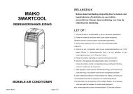
2 <strong>Operator</strong> <strong>Interface</strong> <strong>and</strong> Frequency ConverterControlHigh Power Service Manual for VLT ® FC SeriesFrequency Converters22.5 Frequency Converter Inputs <strong>and</strong> OutputsThe frequency converter operates by receiving control input signals. The frequency converter canalso output status data or control auxiliary devices. Control input is connected to the frequencyconverter in three possible ways. One way for frequency converter control is through the LCP onthe front of the frequency converter when operating in local (h<strong>and</strong>) mode. These inputs includestart, stop, reset, <strong>and</strong> speed reference.Another control source is through serial communication from a serial bus. A serial communicationprotocol supplies comm<strong>and</strong>s <strong>and</strong> references to the frequency converter, can program the frequencyconverter, <strong>and</strong> reads status data from the frequency converter. The serial bus connectsto the frequency converter through the RS-485 serial port or through a communication optioncard.The third way is through signal wiring connected to the frequency converter control terminals (seeillustration below). The frequency converter control terminals are located below the frequencyconverter LCP. Improperly connected control wiring can be the cause of a motor not operating orthe frequency converter not responding to a remote input.Terminal Descriptions1. Digital I/O terminals2. RS-485 (EIA-485) terminal3. Analog I/O terminals4. USB connectorIllustration 2.1: Control Terminals36 MG.90.L1.02 - VLT ® is a registered Danfoss trademark
High Power Service Manual for VLT ® FC SeriesFrequency Converters2 <strong>Operator</strong> <strong>Interface</strong> <strong>and</strong> Frequency ConverterControl2.5.1 Input signalsThe frequency converter can receive two types of remote input signals: digital or analog. Digitalinputs are wired to terminals 18, 19, 20 (common), 27, 29, 32, <strong>and</strong> 33. Analog or digital inputsare wired to terminals 53 or 54 <strong>and</strong> 55 (common). The terminal functions are set by a switch foundby removing the LCP. Some options may include additional terminals.2Analog signals can be either voltage (0 to +10 VDC) or current (0 to 20 mA or 4 to 20 mA). Analogsignals can be varied like dialling a rheostat up <strong>and</strong> down. The frequency converter can be programmedto increase or decrease output in relation to the amount of current or voltage. Forexample, a sensor or external controller may supply a variable current or voltage. The frequencyconverter output, in turn, regulates the speed of the motor connected to the frequency converterin response to the analog signal.Digital signals are a simple binary 0 or 1 which, in effect, act as a switch. Digital signals arecontrolled by a 0 to 24 VDC signal. A voltage signal lower than 5 VDC is a logic 0. A voltage higherthan 10 VDC is a logic 1. Zero is open, one is close. Digital inputs to the frequency converter areswitched comm<strong>and</strong>s such as start, stop, reverse, coast, reset, <strong>and</strong> so on. (Do not confuse thesedigital inputs with serial communication formats where digital bytes are grouped into communicationwords <strong>and</strong> protocols.)The RS-485 serial communication connector is wired to terminals (+) 68 <strong>and</strong> (-) 69. Terminal 61is common <strong>and</strong> may be used for terminating screens only when the control cable run betweenfrequency converters, not between frequency converters <strong>and</strong> other devices. See EarthingScreened Cables in this section for correct methods for terminating a screened control cable.2.5.2 Output signalsThe frequency converter also produces output signals that are carried through either the RS-485serial bus or terminal 42. Output terminal 42 operates in the same manner as the inputs. Theterminal can be programmed for either a variable analog signal in mA or a digital signal (0 or 1)in 24 VDC. In addition, a pulse reference can be provided on terminals 27 <strong>and</strong> 29. Output analogsignals generally indicate the frequency converter frequency, current, torque <strong>and</strong> so on to anexternal controller or system. Digital outputs can be control signals used to open or close a damper,for example, or send a start or stop comm<strong>and</strong> to auxiliary equipment.Additional terminals are Form C relay outputs on terminals 01, 02, <strong>and</strong> 03, <strong>and</strong> terminals 04, 05,<strong>and</strong> 06.Terminals 12 <strong>and</strong> 13 provide 24 VDC low voltage power, often used to supply power to the digitalinput terminals (18-33). Those terminals must be supplied with power from either terminal 12 or13, or from a customer supplied external 24 VDC power source. Improperly connected controlwiring is a common service issue for a motor not operating or the frequency converter not respondingto a remote input.MG.90.L1.02 - VLT ® is a registered Danfoss trademark 37
2 <strong>Operator</strong> <strong>Interface</strong> <strong>and</strong> Frequency ConverterControlHigh Power Service Manual for VLT ® FC SeriesFrequency Converters22.6 Control TerminalsControl terminals must be programmed. Each terminal has specific functions it is capable of performing<strong>and</strong> a numbered parameter associated with it. See table below. The setting selected inthe parameter enables the function of the terminal.It is important to confirm that the control terminal is programmed for the correct function.Parameter settings are displayed by pressingthe [Status] key on the LCP.130BP045.10Use the arrow keys [▲], [▼], [►] <strong>and</strong> [◄] onthe LCP to scroll through parameters.See the Programming Guide for details on changing parameters <strong>and</strong> the functions available foreach control terminal.In addition, the input terminal must be receiving a signal. Confirm that the control <strong>and</strong> powersources are wired to the terminal. Then check the signal.Signals can be checked in two ways. Digital input can be selected for display by pressing [status]key as discussed previously, or a voltmeter may be used to check for voltage at the control terminal.See procedure details at Input Terminal Test in Section 6.In summary, for proper frequency converter functioning, the frequency converter inputcontrol terminals must be:1. wired properly2. powered3. programmed correctly for the intended function4. receiving a signal38 MG.90.L1.02 - VLT ® is a registered Danfoss trademark
High Power Service Manual for VLT ® FC SeriesFrequency Converters2 <strong>Operator</strong> <strong>Interface</strong> <strong>and</strong> Frequency ConverterControl2.7 Control Terminal FunctionsThe following describes the functions of the control terminals. Many of these terminals have multiplefunctions determined by parameter settings. Some options provide additional terminals. SeeIllustration 2-2.2Terminal No. Function01, 02, 03 <strong>and</strong> 04, Two Form C output relays. Maximum 240 VAC, 2 A. Minimum 24 VDC,05, 0610 mA or 24 VAC, 100 mA. Can be used for indicating status <strong>and</strong> warnings.Physically located on the power card.12, 13 24 VDC power supply to digital inputs <strong>and</strong> external transducers. Themaximum output current is 200 mA.18, 19, 27, 29, 32,33Digital inputs for controlling the frequency converter. R = 2 kohm. Lessthan 5 V = logic 0 (open). Greater than 10 V = logic 1 (closed). Terminals27 <strong>and</strong> 29 are programmable as digital/pulse outputs.20 Common for digital inputs.37 0–24 VDC input for safety stop (some units).39 Common for analog <strong>and</strong> digital outputs.42 Analog <strong>and</strong> digital outputs for indicating values such as frequency, reference,current <strong>and</strong> torque. The analog signal is 0/4 to 20 mA at amaximum of 500 Ω. The digital signal is 24 VDC at a minimum of 500 Ω.50 10 VDC, 15 mA maximum analog supply voltage for potentiometer orthermistor.53, 54 Selectable for 0 to 10 VDC voltage input, R = 10 kΩ, or analog signals0/4 to 20 mA at a maximum of 200 Ω. Used for reference or feedbacksignals. A thermistor can be connected here.55 Common for terminals 53 <strong>and</strong> 54.61 RS-485 common.68, 69 RS 485 interface <strong>and</strong> serial communication.Term 18 19 27 29 32 33 37 53 54 42 1-3 4-6Par. 5-10 5-11 5-12 5-13 5-14 5-15 5-19 6-1* 6-2* 6-5* 5-4* 5-4*Table 2.2: Control Terminals <strong>and</strong> Associated ParameterControl terminals must be programmed. Each terminal has specific functions it is capable of performing<strong>and</strong> a numbered parameter associated with it. The setting selected in the parameterenables the function of the terminal. See the FC Series Operating Instructions for details.MG.90.L1.02 - VLT ® is a registered Danfoss trademark 39
2 <strong>Operator</strong> <strong>Interface</strong> <strong>and</strong> Frequency ConverterControlHigh Power Service Manual for VLT ® FC SeriesFrequency Converters2Illustration 2.2: Control Terminals Electrical Diagram40 MG.90.L1.02 - VLT ® is a registered Danfoss trademark
High Power Service Manual for VLT ® FC SeriesFrequency Converters2 <strong>Operator</strong> <strong>Interface</strong> <strong>and</strong> Frequency ConverterControl2.8 Earthing Screened CablesIt is recommended that screened control cables be connected with cable clamps at both ends tothe metal cabinet of the frequency converter. Table 2-3 shows earth cabling for optimal results.2Correct earthing Control cables <strong>and</strong> cables for serial communication must be fittedwith cable clamps at both ends to ensure the best possible electrical connection.Incorrect earthing Do not use twisted cable ends (pigtails) since these increasescreen impedance at high frequencies.Earth potential protection When the earth potential between the frequencyconverter <strong>and</strong> the PLC or other interface device is different, electrical noise mayoccur that can disturb the entire system. This can be resolved by fitting an equalizingcable next to the control cable. Minimum cable cross section is 8 AWG.50/60 Hz earth loops When using very long control cables, 50/60 Hz earth loopsmay occur that can disturb the entire system. This can be resolved by connectingone end of the screen with a 100 nF capacitor <strong>and</strong> keeping the lead short.Serial communication control cables Low frequency noise currents betweenfrequency converters can be eliminated by connecting one end of the screenedcable to frequency converter terminal 61. This terminal connects to earth throughan internal RC link. It is recommended to use twisted-pair cables to reduce thedifferential mode interference between conductors.Table 2.3: Earthing Screened CablesMG.90.L1.02 - VLT ® is a registered Danfoss trademark 41
3 Internal Frequency Converter OperationHigh Power Service Manual for VLT ® FC SeriesFrequency Converters342 MG.90.L1.02 - VLT ® is a registered Danfoss trademark
High Power Service Manual for VLT ® FC SeriesFrequency Converters3 Internal Frequency Converter Operation3 Internal Frequency Converter Operation3.1 GeneralThis section is intended to provide an operational overview of the frequency converter’s mainassemblies <strong>and</strong> circuitry. With this information, a repair technician should have a better underst<strong>and</strong>ingof the frequency converter's operation <strong>and</strong> aid in the troubleshooting process.33.2 Description of OperationA frequency converter is an electronic controller that supplies a regulated amount of AC power toa three phase induction motor in order to control the speed of the motor. By supplying variablefrequency <strong>and</strong> voltage to the motor, the frequency converter controls the motor speed, or maintainsa constant speed as the load on the motor changes. The frequency converter can also stop<strong>and</strong> start a motor without the mechanical stress associated with a line start.In its basic form, the frequency converter can be divided into four main sections: rectifier, intermediatecircuit, inverter, <strong>and</strong> control (see Illustration 3-1).Illustration 3.1: Control Card LogicTo provide an overview, the main frequency converter components will be grouped into threecategories consisting of the control logic section, logic to power interface, <strong>and</strong> power section. Inthe sequence of operation description, these three sections will be covered in greater detail whiledescribing how power <strong>and</strong> control signals move throughout the frequency converter.MG.90.L1.02 - VLT ® is a registered Danfoss trademark 43
3 Internal Frequency Converter OperationHigh Power Service Manual for VLT ® FC SeriesFrequency Converters3.2.1 Logic Section3The control card contains most of the logic section (see Illustration 3-2). The primary logic elementof the control card is a microprocessor, which supervises <strong>and</strong> controls all functions of frequencyconverter operation. In addition, separate PROMs contain the parameters to provide the user withprogrammable options. These parameters are programmed to enable the frequency converter tomeet specific application requirements. This data is then stored in an EEPROM which providessecurity during power-down <strong>and</strong> also allows the flexibility to change the operational characteristicsof the frequency converter.A custom integrated circuit generates a pulse width modulation (PWM) waveform which is thensent to the interface circuitry located on the power card.Illustration 3.2: Logic SectionThe PWM waveform is created using an improved control scheme called VVC plus , a further developmentof the earlier VVC (Voltage Vector Control) system. VVC plus provides a variable frequency<strong>and</strong> voltage to the motor which matches the requirements of the motor. Also available is thecontinuous pulsing SFAVM PWM. Selection can be made in parameter group 14-**. The dynamicresponse of the system changes to meet the variable requirements of the load.Another part of the logic section is the local control panel (LCP). This is a removable keypad/display mounted on the front of the frequency converter. The LCPprovides the interface betweenthe frequency converter's internal digital logic <strong>and</strong> the operator.All the frequency converter's programmable parameter settings can be uploaded into the EEPROMof the LCP. This function is useful for maintaining a backup frequency converter profile <strong>and</strong> parameterset. It can also be used, through its download function, in programming other frequencyconverters or to restore a program to a repaired unit. The LCP is removable during operation toprevent undesired program changes. With the addition of a remote mounting kit, the LCP can bemounted in a remote location of up to ten feet away.Control terminals, with programmable functions, are provided for input comm<strong>and</strong>s such as run,stop, forward, reverse <strong>and</strong> speed reference. Additional output terminals are provided to supplysignals to run peripheral devices or for monitoring <strong>and</strong> reporting status.44 MG.90.L1.02 - VLT ® is a registered Danfoss trademark
High Power Service Manual for VLT ® FC SeriesFrequency Converters3 Internal Frequency Converter OperationThe control card logic is capable of communicating via serial link with outside devices such aspersonal computers or programmable logic controllers (PLC).The control card also provides two voltage supplies for use from the control terminals. The 24VDC is used for switching functions such as start, stop <strong>and</strong> forward/reverse. The 24 VDC supplyis also capable of supplying 200 mA of power, part of which may be used to power externalencoders or other devices. A 10 VDC supply on terminal 50 is rated at 17 mA is also available foruse with speed reference circuitry.3The analog <strong>and</strong> digital output signals are powered through an internal frequency converter supply.Two relays for monitoring the status of the frequency converter are located on the power card.These are programmable through parameter group 5-4*. The relays are Form C, meaning it hasone normally open contact <strong>and</strong> one normally closed contact on a single throw. The contacts ofthe relay are rated for a maximum load of 240 VAC at 2 Amps resistance.The logic circuitry on the control card allow for the addition of option modules for synchronisingcontrol, serial communications, additional relays, the cascade pump controller, or custom operatingsoftware.3.2.2 Logic to Power <strong>Interface</strong>The logic to power interface isolates the high voltage components of the power section from thelow voltage signals of the logic section. The interface section consists of the power card <strong>and</strong> gatedrive card.Much of the fault processing for output short circuit <strong>and</strong> earth fault conditions is h<strong>and</strong>led by thecontrol card. The power card provides conditioning of these signals. Scaling of current feedback<strong>and</strong> voltage feedback is accomplished by the control card.The power card contains a switch mode power supply (SMPS) which provides the unit with 24VDC, +18 VDC, –18 VDC <strong>and</strong> 5 VDC operating voltage. The logic <strong>and</strong> interface circuitry is poweredby the SMPS. The SMPS is supplied by the DC bus voltage. The frequency converters can bepurchased with an optional secondary SMPS which is powered from a customer supplied 24 VDCsource. This secondary SMPS provides power to the logic circuitry with main input disconnected.It can keep units with communication options live on a network when the frequency converter isnot powered from the mains.Circuitry for controlling the speed of the cooling fans is also provided on the power card.The gate frequency converter signals from the control card to the output transistors (IGBTs) areisolated <strong>and</strong> buffered on the gate drive card. In units that have the dynamic brake option, thedriver circuits for the brake transistors are also located on this card.MG.90.L1.02 - VLT ® is a registered Danfoss trademark 45
3 Internal Frequency Converter OperationHigh Power Service Manual for VLT ® FC SeriesFrequency Converters3.2.3 Power Section3The high voltage power section consists of AC input terminals, AC <strong>and</strong> DC bus bars, fusing, harnessing,AC output, <strong>and</strong> optional components. The power section (see Illustration 3-3) alsocontains circuitry for the soft charge <strong>and</strong> SCR/diode modules in the rectifier; the DC bus filtercircuitry containing the DC coils, often referred to as the intermediate or DC bus circuit; <strong>and</strong> theoutput IGBT modules which make up the inverter section.In conjunction with the SCR/diode modules, the soft charge circuit limits the inrush current whenpower is first applied <strong>and</strong> the DC bus capacitors are charging. This is accomplished by the SCRsin the modules being held off while charging current passes through the soft charge resistors,thereby limiting the current. The DC bus circuitry smooths the pulsating DC voltage created bythe conversion from the AC supply.The DC coil is a single unit with two coils wound on a common core. One coil resides in the positiveside of the DC bus <strong>and</strong> the other in the negative. The coil aids in the reduction of mains harmonics.The DC bus capacitors are arranged into a capacitor bank along with bleeder <strong>and</strong> balancing circuitry.Due to the requirement for higher power capacity, some frequency converters have twocapacitor banks connected in parallel.The inverter section is made up of six IGBTs, commonly referred to as switches. One switch isnecessary for each half phase of the three-phase power, for a total of six. The six IGBTs arecontained in a single module. Due to higher current h<strong>and</strong>ling requirements, some models containtwo or three larger six-pack style modules. In these units, each switch (half phase) is made up oftwo or three IGBTs in parallel.A Hall effect type current sensor is located on each phase of the output to measure motor current.This type of device is used instead of more common current transformer (CT) devices in order toreduce the amount of frequency <strong>and</strong> phase distortion that CTs introduce into the signal. With Hallsensors, the average, peak, <strong>and</strong> earth leakage currents can be monitored.Illustration 3.3: Typical Power Section46 MG.90.L1.02 - VLT ® is a registered Danfoss trademark
High Power Service Manual for VLT ® FC SeriesFrequency Converters3 Internal Frequency Converter Operation3.3 Sequence of Operation3.3.1 Rectifier SectionWhen input power is first applied to the frequency converter, it enters through the input terminals(L1, L2, L3) <strong>and</strong> on to the disconnect or/<strong>and</strong> RFI option, depending on the unit's configuration(see Illustration 3-4). If equipped with optional fuses, these fuses (FU1, FU2, FU3) limit damagecaused by a short circuit in the power section. The SCRs, in the combined SCR/diode modules,are not gated so current can travel to the rectifier on the soft charge card. In E frequency convertermodels, the SCR <strong>and</strong> diode modules are separate. Additional fuses located on the soft charge cardprovide protection in the event of a short in the soft charge or fan circuits. Three phase power isalso branched off <strong>and</strong> sent to the power card. It provides the power card with a reference of themain supply voltage <strong>and</strong> provides a supply voltage for the cooling fans.3During the charging process, the top diodes of the soft charge rectifier conduct <strong>and</strong> rectify duringthe positive half cycle. The diodes in the main rectifier conduct during the negative half cycle. TheDC voltage is applied to the bus capacitors through the soft charge resistor. The purpose ofcharging the DC bus through this resistor is to limit the high inrush current that would otherwisebe present.Positive temperature coefficient (PTC) resistors located on the soft charge card are in series withthe soft charge resistor. Frequent cycling of the input power or the DC bus charging over anextended time can cause the PTC resistors to heat up due to the current flow. Resistance of thePTC device increases with temperature, eventually adding enough resistance to the circuit to preventsignificant current flow. This protects the soft charge resistor from damage along with anyother components that could be damaged by continuous attempts to charge the DC bus.The low voltage power supplies are activated when the DC bus reaches approximately 50 VDCless than the alarm voltage low for the DC bus. After a short delay, an inrush enable signal is sentfrom the control card to the power card SCR gating circuit. The SCRs are automatically gated whenforward biased, as a result acting similar to an uncontrolled rectifier.When the DC bus capacitors are fully charged, the voltage on the DC bus will be equal to the peakvoltage of the input mains. Theoretically, this can be calculated by multiplying the mains value by1.414 (VAC x 1.414). However, since AC ripple voltage is present on the DC bus, the actual DCvalue will be closer to VAC x 1.38 under unloaded conditions <strong>and</strong> may drop to VAC x 1.32 whilerunning under load. For example, a frequency converter connected to a nominal 460 V line, whilesitting idle, the DC bus voltage will be approximately 635 VDC (460 x 1.38).As long as power is applied to the frequency converter, this voltage is present in the intermediatecircuit <strong>and</strong> the inverter circuit. It is also fed to the Switch Mode Power Supply (SMPS) on the powercard <strong>and</strong> is used for generating all other low voltage supplies.MG.90.L1.02 - VLT ® is a registered Danfoss trademark 47
RL1SL2TL3GND91929394FU1FU2FU3175L0109-GRAPHIC175L0110-NUMERICFK1FK2FK3MK1RFI CARD+-3 2 1-+FK4FK5FK6RFI SWITCHRS-485MK10361 68 69S + -1213RSTDIGITAL INPUTS18MK10219273929ANALOG I/OMK101423250335344205413755R' S' T'MK2SOFTCHARGE BOARDR'S'T'+SCR-SCRACAB144MK100SCRGATE DRIVERCURRENTSCALINGCARD3 6 2 5 1 4DC INDUCTOR1 2 3TMPGND18 PULSE NTCMK10390kW = 130B6805110kW = 130B6806+DC-DCMK105190835 190836 1908363 2 1 6 5 4 3 2 1 3 5 4 13 11 12 9 8 1 61L1 L2 L1 L2 L1 L1FANS105 104 106X2 X1102 100103 101<strong>NO</strong> C NCS AUX_ST AUX_TMK107FK102FK103TEST CONNECTOR+-RFI SWITCHMK400+DC-DCMK250GUNEUN1 2 3+-MK101VDD RFI SWRL2MK350GUPGUPEUP1 2 3MK112RELAY 1 RELAY 2C <strong>NO</strong> NC C <strong>NO</strong> NC1 2 3 4 5 6MK450GVN1GVN+-EVN2PRE TESTMK550GVPGVPEVP3 1 2 3UDC+ABCBAL CKTPCA9130B6885HF SWITCHMK6501GWN+-+-2MK750GWPEWP3 1 2 3MK850GBPBRKBRN1 2 315GUPMK102EUPEUN1 5 6 104 5 8 1ELO1EUP1GLO1MK100CUP1 GUP1 EUP1 GLO1 ELO130MK109UPMK106UNGVPMK103GVNEVP1 5 6EVN104 5 8 1EUP2GLO2MK100ELO21MK104CUP2 GUP2 EUP2 GLO2 ELO2 CUP3 GUP3 EUP3 GLO3 ELO3VPVNEWP1 5 6104 5 8 1EUP3GLO3MK100ELO3MK100MK103OUTNTCNTC1 2 31 2 3NTC1NTC2INBRCBRNGBPMK102WPWNMK1061058361SENS 10DET 11VPOSIU1VNEG 3VPOS 4IV1 5VNEG 6VPOS 7IW1 8VNEG 16VDDHF SW14RL2 15VDD 12CC FANFA<strong>NO</strong> 13GND 9E1/C2E2G2R'S'T'UDC-321 1+-32IGBT4UDC+HF SWITCH321I<strong>NO</strong>UTCOMHEATSINK/DOORFAN TRANSFORMERASSY 175L9471WHTBLKGRNBLK1 12 23 382+M-+ M -+12345M-46 61231231235123123WHTBLUORNGRNBLKBLKGNDEXT BRAKERESISTORFAN+FAN+FAN-FAN-UDC-RS+RS-FAN-FAN+TMP-HEATSINKFAN CAPACITOR10313969798958988DOOR FANNEMA 1,IP 54UNITS ONLY.TOP FANTOP FAN3 Internal Frequency Converter OperationHigh Power Service Manual for VLT ® FC SeriesFrequency Converters3LEGEND:90kW = FC-302 P90K T5FC-202 P100 T4FC-102 P110 T4110kW = FC-302 P110 T5FC-202 P132 T4FC-102 P132 T4LCP1DISPLAYCONTROLPANELFC-X02CONTROLCBL1130B0096CARDIP54/NEMA12PCA1CONTROL CARD VARIANTSFC-302 - 130B7204FC-302 - 130B7205 COATEDFC-102/202 - 130B7206 WITH SAFE STOPFC-102/202 - 130B7207 COATED, WITH SAFE STOPFC-102/202 - 130B7226 <strong>NO</strong> SAFE STOPFC-102/202 - 130B7213 COATED, <strong>NO</strong> SAFE STOPFK102CBL2130B0057CBL13190847MK110PCA4R S TMK111FU520203AB(DISABLE MAINS RECTIFIER)EXTERNAL BRAKETEMP SWITCHCBL15190820AC3 2 1GUNAUX FANPOWER CARDPCA3130B6893130B6895-COATEDGWNEWNGWPCBL173x190831MK104GUNUCBL16190830CBL18GATE DRIVE CARDPCA5130B6857130B6856 (COATED W/BRAKE)VCBL19GWPGWNWAUX_SEWNAUX_TAUX_SAUX_TTMP+MK105NTCBRK1 6 5CBL20190808CURRENTSENSORSCBL21190832CBL8MAINSCURIU'IV'IW'6 4 1190843RSTBRKMK112BRAKE GATERES CARDPCA13130B6865CBL9190812CBL5EM GATE COL190848CN2FU420203BRAKE OPTIONTR116150CBL23 190834CBL22 190833BRAKE IGBT292ASSY 175L9421CN4CBL1219081781 R-TB3CN3CN5CN6R+HS FAN ASSEMBLY175L9400F127651HEATSINKFANC1F227653F4ASSY 175L8314F5USED ONCHASSIS ANDIP00 UNITSONLY.ASSY 175L8314NEMA 12,IP 21,USED ONCHASSIS ANDIP00 UNITSONLY.CBL14190815GUP1UGUP2GATE RESISTOR CARDPCA690kW=130B6858110kW=130B6859VGUP3W90kW=16000110kW=16001HF CARDPCA8130B6870CBANK1DC CAP BANK ASSY90kW=175L9426110kW=175L9427SCR1 SCR2 SCR32379 2379 2379C2 C3 C41031210312 1031216005SW1 3x20202 20207PCA12PCA 12:130B6872-RFI ONLY130B6873-COATED, RFI ONLY130B6874-USED WITH DISC SW AND FUSES130B6875-COATED, USED WITH DISC SW AND FUSESCBL15190820CBL9CBL24190812190846IGBT190kW=175L9433110kW=175L9405IVL316005IWL416005PCA11130B6866130B6868 (Coated)CBL25190813R127 OhmsAssy 175L9472CBL5190848130BX187.10NTCL1IUL2TB2UTB1DISC/FUSE OPTIONRFI OPTIONR S TMK1001 2 3MK1ECO<strong>NO</strong>PACK+ MODULEVWGNDLOAD SHARE OPTIONTB4+DC-DCMK1MK4MK3No RFI relay on 525 - 690VUnits. E1 units have 2 RFIcardsIllustration 3.4: Rectifier circuit48 MG.90.L1.02 - VLT ® is a registered Danfoss trademark
High Power Service Manual for VLT ® FC SeriesFrequency Converters3 Internal Frequency Converter Operation3.3.2 Intermediate SectionFollowing the rectifier section, voltage passes to the intermediate section. (see Illustration 3-5).This rectified voltage is smoothed by an LC filter circuit consisting of the DC bus inductor <strong>and</strong> theDC bus capacitor bank.The DC bus inductor provides series impedance to changing current. This aids the filtering processwhile reducing harmonic distortion to the input AC current waveform normally inherent in rectifiercircuits.3The DC capacitor bank assembly consists of up to eight capacitors arranged in series/parallelconfiguration. Higher power units have two capacitor bank assemblies. Also contained within theassembly is the bleeder/balance circuitry. This circuitry maintains equal voltage drops across eachcapacitor <strong>and</strong> provides a current path for discharging the capacitors once power has been removedfrom the frequency converter.Also located in the intermediate section is the high frequency (HF) filter card. It contains a highfrequency filter circuit to reduce naturally occurring currents in the HF range to prevent interferencewith other sensitive equipment in the area. The circuit, as with other RFI filter circuitry, canbe sensitive to unbalanced phase-to-earth voltages in the three-phase AC input line. This canoccasionally result in nuisance overvoltage alarms. For this reason, the high frequency filter cardon 380–500 V range frequency converters, contains a set of relay contacts in the earth connectionof the filter capacitors. The relay is tied into the RFI/HF switch, which can be switched on or offin par. 14-50 RFI Filter. This disconnects the earth references to all filters should unbalancedphase-to-earth voltages create nuisance overvoltage conditions.For 525–690 V frequency converters, there are no relay contacts that disconnect the earthing.MG.90.L1.02 - VLT ® is a registered Danfoss trademark 49
3 Internal Frequency Converter OperationHigh Power Service Manual for VLT ® FC SeriesFrequency Converters3Illustration 3.5: Intermediate section50 MG.90.L1.02 - VLT ® is a registered Danfoss trademark
High Power Service Manual for VLT ® FC SeriesFrequency Converters3 Internal Frequency Converter Operation3.3.3 Inverter SectionIn the inverter section (see Illustration 3-7), gate signals are delivered from the control card,through the power card <strong>and</strong> gate frequency converter card to the gates of the IGBTs. The seriesconnection of each set of IGBTs is delivered to the output, first passing through the current sensors.Once a run comm<strong>and</strong> <strong>and</strong> speed reference are present, the IGBTs begin switching to create theoutput waveform, as shown in Illustration 3-6. Looking at the phase-to-phase voltage waveformwith an oscilloscope, it can be seen that the Pulse Width Modulation (PWM) principal creates aseries of pulses which vary in width. Basically, the pulses are narrower as zero crossing is approached<strong>and</strong> wider the farther from zero crossing. The width is controlled by the pulse durationof applied DC voltage. Although the voltage waveform is a consistent amplitude, the inductancewithin the motor windings will serve to average the voltage delivered <strong>and</strong> so, as the pulse widthof the waveform varies, the average voltage seen by the motor varies as well. This then equatesto the resultant current waveform which takes on the sine wave shape that we expect to see inan AC system. The frequency of the waveform is then determined by the rate at which the pulsesoccur. By employing a sophisticated control scheme, the frequency converter is capable of deliveringa current waveform that nearly replicates a true AC sine wave.3This waveform, as generated by the Danfoss VVCplus PWM principle at the control card, providesoptimal performance <strong>and</strong> minimal losses in the motor.Hall effect current sensors monitor the output current <strong>and</strong> deliver proportional signals to the powercard where they are buffered <strong>and</strong> delivered to the control card. These current signals are used bythe control card logic to determine proper waveform compensations based on load conditions.They further serve to detect overcurrent conditions, including earth faults <strong>and</strong> phase-to-phaseshorts on the output.During normal operation, the power card <strong>and</strong> control card are monitoring various functions withinthe frequency converter. The current sensors provide current feedback information. The DC busvoltage <strong>and</strong> mains voltage are monitored as well as the voltage delivered to the motor. A thermalsensor mounted inside one of IGBT modules provides heatsink temperature feedback.130BX136.10Illustration 3.6: Output Voltage <strong>and</strong> Current WaveformsMG.90.L1.02 - VLT ® is a registered Danfoss trademark 51
RL1SL2TL3GNDLEGEND:90kW = FC-302 P90K T5FC-202 P100 T4FC-102 P110 T4110kW = FC-302 P110 T5FC-202 P132 T4FC-102 P132 T49192TB19394DISC/FUSE OPTIONSW120202FU1FU2FU33x20207LCP1DISPLAYCONTROLPANEL175L0109-GRAPHIC175L0110-NUMERICRFI OPTIONPCA12CBL1130B0096IP54/NEMA12CBL15190820-RFI SWITCH+PCA 12:130B6872-RFI ONLY130B6873-COATED, RFI ONLY130B6874-USED WITH DISC SW AND FUSES130B6875-COATED, USED WITH DISC SW AND FUSESFK1FK2FK3MK1RFI CARD+-3 2 1FK4FK5FK6RS-485MK10361 68 69S + -12FC-X02CONTROLCARDPCA113CONTROL CARD VARIANTSFC-302 - 130B7204FC-302 - 130B7205 COATEDFC-102/202 - 130B7206 WITH SAFE STOPFC-102/202 - 130B7207 COATED, WITH SAFE STOPFC-102/202 - 130B7226 <strong>NO</strong> SAFE STOPFC-102/202 - 130B7213 COATED, <strong>NO</strong> SAFE STOPCBL24190846RSTDIGITAL INPUTS18MK10219273929ANALOG I/OMK10142325033534420543755190812SOFTCHARGE BOARDPCA11130B6866130B6868 (Coated)1CBL2130B0057R S TMK1R' S' T'MK2CBL9MK3MK4R'S'T'+SCR-SCRACABCBL13190847SCRGATE DRIVERR S TCBL25190813144MK100PCA4CURRENTSCALINGCARD3 6 2 5 1 420203CBL1419081590kW=16000110kW=16001L1DC INDUCTORR127 OhmsAssy 175L94721 2 3TMPGND18 PULSE NTCMK103FU590kW = 130B6805110kW = 130B6806+DCA-DCB(DISABLE MAINS RECTIFIER)EXTERNAL BRAKETEMP SWITCH190835 190836 190836AUX FAN3 2 1 6 5 4 3 2 1 3 5 4 13 11 12 9 8 1 61L1 L2 L1 L2 L1 L1FANS105 104 106X2 X1102 100103 101<strong>NO</strong> C NCS AUX_ST AUX_TMK107FK102FK103TEST CONNECTORPOWER CARDPCA3MK105CBL15190820+-RFI SWITCHMK400+DCA-DCCMK250GUNGUNEUN1 2 3HF CARDPCA8130B6870+-MK101VDD RFI SWRL2MK350GUPGUPEUP1 2 3130B6893130B6895-COATEDMK112RELAY 1 RELAY 2C <strong>NO</strong> NC C <strong>NO</strong> NC1 2 3 4 5 6MK450GVN1GVNEVN2CBL5190848+-PRE TESTMK550GVPGVPCBANK1DC CAP BANK ASSY90kW=175L9426110kW=175L9427UDC+ABCBAL CKTPCA9130B6885MK1EVP3 1 2 3HF SWITCH151MK109CBL16190830GATE DRIVE CARDMK106PCA5130B6857130B6856 (COATED W/BRAKE)MK650 MK750 MK850MK103MK104GWN GWP BRK1 2 3 1 2 3 1 2 3 1 5 6 101 5 6 101 5 6 10CBL17CBL18CBL193x1908314 5 8 14 5 8 14 5 8 1GWN+-+-EWNGWPEWPGBPBRNGUPGUNEUPEUNGUP1ELO1EUP1GLO1MK100MK100MK100GATE RESISTOR CARDPCA690kW=130B6858110kW=130B6859CUP1 GUP1 EUP1 GLO1 ELO13010312 10312UPUNGVPGVNEVPEUP2GLO2GUP2EVNELO2CUP2 GUP2 EUP2 GLO2 ELO2 CUP3 GUP3 EUP3 GLO3 ELO3GWPGWNVPVNEWPEUP3GLO3GUP3EWNELO3MK100NTCTMP+MK103OUTNTCNTC1 2 31 2 3NTC1NTCNTC2MK102CBL20190808INBRCBRNGBPWPWNMK106CBL2119083210312CBL8IW'HF SW190843RSTSENS 10CUR DET 11VPOS 1IU' IU1 2VNEG 3VPOS 4IV' IV1 5VNEG 6VPOS 7IW1 8VNEGVDDCC FANFA<strong>NO</strong> 13GND 9E1/C2E2G2PCA13130B6865IGBT190kW=175L9433110kW=175L940516VDD 14RL2 1512BRAKE GATERES CARDCBL91908121058361CBL5GATER'S'T'190848UDC-ECO<strong>NO</strong>PACK+ MODULECN232+-321 120203BRAKE OPTIONIGBT4UDC+FU4HF SWITCHTR116150HEATSINK/DOORFAN TRANSFORMERASSY 175L9471BRAKE IGBT292ASSY 175L9421321I<strong>NO</strong>UTCOMCBL23CBL22190834190833WHTBLKGRNBLKCN41 12 23 316005+CBL1219081781 R-82TB3IUMIV1600516005-+ M -+CN312345IWMR+-123456 6CN51 12 23 3CN61 12 23 3HS FAN ASSEMBLY175L9400EXT BRAKERESISTORL2L3L4WHTBLUORNGRNBLKBLKF127651GNDFAN+HEATSINKFANC1F410313UDC-RS+RS-F227653FAN-FAN+TMP-FAN-ONLY.ASSY 175L8314F5FAN+FAN-ONLY.ASSY 175L8314TB2969798958988UVWGNDLOAD SHARE OPTIONTB4HEATSINKFAN CAPACITORDOOR FANNEMA 1,NEMA 12,IP 21,IP 54UNITS ONLY.TOP FANUSED ONCHASSIS ANDIP00 UNITSTOP FANUSED ONCHASSIS ANDIP00 UNITS+DC-DC3 Internal Frequency Converter OperationHigh Power Service Manual for VLT ® FC SeriesFrequency Converters3FK102MK110MK1113 2 1MK104UMK102VWAUX_SAUX_TAUX_SAUX_TMK105BRK1 6 5CURRENTSENSORSMAINS6 4 1BRKMK1EM COLSCR1 SCR2 SCR32379 2379 2379MK100UVWC2 C3 C41 2 3Illustration 3.7: Inverter section130BX186.1052 MG.90.L1.02 - VLT ® is a registered Danfoss trademark
RL1SL2TL3GNDLEGEND:90kW = FC-302 P90K T5FC-202 P100 T4FC-102 P110 T4110kW = FC-302 P110 T5FC-202 P132 T4FC-102 P132 T49192TB19394DISC/FUSE OPTIONSW120202FU1FU2FU33x20207LCP1DISPLAYCONTROLPANEL175L0109-GRAPHIC175L0110-NUMERICRFI OPTIONPCA12CBL1130B0096IP54/NEMA12CBL15190820-RFI SWITCH+PCA 12:130B6872-RFI ONLY130B6873-COATED, RFI ONLY130B6874-USED WITH DISC SW AND FUSES130B6875-COATED, USED WITH DISC SW AND FUSESFK1FK2FK3MK1RFI CARD+-3 2 1FK4FK5FK6RS-485MK10361 68 69S + -12FC-X02CONTROLCARDPCA113CONTROL CARD VARIANTSFC-302 - 130B7204FC-302 - 130B7205 COATEDFC-102/202 - 130B7206 WITH SAFE STOPFC-102/202 - 130B7207 COATED, WITH SAFE STOPFC-102/202 - 130B7226 <strong>NO</strong> SAFE STOPFC-102/202 - 130B7213 COATED, <strong>NO</strong> SAFE STOPCBL24190846RSTDIGITAL INPUTS18MK10219273929ANALOG I/OMK10142325033534420543755190812SOFTCHARGE BOARDPCA11130B6866130B6868 (Coated)1CBL2130B0057R S TMK1R' S' T'MK2CBL9MK3MK4R'S'T'+SCR-SCRACABCBL13190847SCRGATE DRIVERR S TCBL25190813144MK100PCA4CURRENTSCALINGCARD3 6 2 5 1 420203CBL1419081590kW=16000110kW=16001L1DC INDUCTORR127 OhmsAssy 175L94721 2 3TMPGND18 PULSE NTCMK103FU590kW = 130B6805110kW = 130B6806+DCA-DCB(DISABLE MAINS RECTIFIER)EXTERNAL BRAKETEMP SWITCH190835 190836 190836AUX FAN3 2 1 6 5 4 3 2 1 3 5 4 13 11 12 9 8 1 61L1 L2 L1 L2 L1 L1FANS105 104 106X2 X1102 100103 101<strong>NO</strong> C NCS AUX_ST AUX_TMK107FK102FK103TEST CONNECTORPOWER CARDPCA3MK105CBL15190820+-RFI SWITCHMK400+DCA-DCCMK250GUNGUNEUN1 2 3HF CARDPCA8130B6870+-MK101VDD RFI SWRL2MK350GUPGUPEUP1 2 3130B6893130B6895-COATEDMK112RELAY 1 RELAY 2C <strong>NO</strong> NC C <strong>NO</strong> NC1 2 3 4 5 6MK450GVN1GVNEVN2CBL5190848+-PRE TESTMK550GVPGVPCBANK1DC CAP BANK ASSY90kW=175L9426110kW=175L9427UDC+ABCBAL CKTPCA9130B6885MK1EVP3 1 2 3HF SWITCH151MK109CBL16190830GATE DRIVE CARDMK106PCA5130B6857130B6856 (COATED W/BRAKE)MK650 MK750 MK850MK103MK104GWN GWP BRK1 2 3 1 2 3 1 2 3 1 5 6 101 5 6 101 5 6 10CBL17CBL18CBL193x1908314 5 8 14 5 8 14 5 8 1GWN+-+-EWNGWPEWPGBPBRNGUPGUNEUPEUNGUP1ELO1EUP1GLO1MK100MK100MK100GATE RESISTOR CARDPCA690kW=130B6858110kW=130B6859CUP1 GUP1 EUP1 GLO1 ELO13010312 10312UPUNGVPGVNEVPEUP2GLO2GUP2EVNELO2CUP2 GUP2 EUP2 GLO2 ELO2 CUP3 GUP3 EUP3 GLO3 ELO3GWPGWNVPVNEWPEUP3GLO3GUP3EWNELO3MK100NTCTMP+MK103OUTNTCNTC1 2 31 2 3NTC1NTCNTC2CBL20190808INBRCBRNGBPMK102WPWNMK106CBL2119083210312CBL8190843RSTPCA13130B6865IGBT190kW=175L9433110kW=175L94051058361SENS 10CUR DET 11VPOS 1IU' IU1 2VNEG 3VPOS 4IV' IV1 5VNEG 6VPOS 7IW' IW1 8VNEG 16VDDHF SW14RL2 15VDD 12CC FANFA<strong>NO</strong> 13GND 9E1/C2E2G2BRAKE GATERES CARDCBL9190812CBL5GATER'S'T'190848UDC-ECO<strong>NO</strong>PACK+ MODULECN232+-321 120203BRAKE OPTIONIGBT4UDC+FU4HF SWITCHTR116150HEATSINK/DOORFAN TRANSFORMERASSY 175L9471BRAKE IGBT292ASSY 175L9421321I<strong>NO</strong>UTCOMCBL23CBL22190834190833WHTBLKGRNBLKCN41 12 23 316005+CBL1219081781 R-82TB3IUMIV1600516005-+ M -+CN312345IWMR+-123456 6CN51 12 23 3CN61 12 23 3HS FAN ASSEMBLY175L9400EXT BRAKERESISTORL2L3L4WHTBLUORNGRNBLKBLKF127651GNDFAN+HEATSINKFANC1F410313UDC-RS+RS-F227653FAN-FAN+TMP-FAN-ONLY.ASSY 175L8314F5FAN+FAN-ONLY.ASSY 175L8314TB2969798958988UVWGNDLOAD SHARE OPTIONTB4HEATSINKFAN CAPACITORDOOR FANNEMA 1,NEMA 12,IP 21,IP 54UNITS ONLY.TOP FANUSED ONCHASSIS ANDIP00 UNITSTOP FANUSED ONCHASSIS ANDIP00 UNITS+DC-DCHigh Power Service Manual for VLT ® FC SeriesFrequency Converters3 Internal Frequency Converter Operation3.3.4 Brake OptionFor frequency converters equipped with the dynamic brake option, a brake IGBT along with terminals81(R-) <strong>and</strong> 82(R+) is included for connecting an external brake resistor.The function of the brake IGBT (see Illustration 3-8) is to limit the voltage in the intermediatecircuit, whenever the maximum voltage limit is exceeded. It does this by switching the externallymounted resistor across the DC bus to remove excess DC voltage present on the bus capacitors.Excess DC bus voltage is generally a result of an overhauling load causing regenerative energy tobe returned to the DC bus. This occurs, for example, when the load frequency converters themotor causing the voltage to return to the DC bus circuit.3Placing the brake resistor externally has the advantages of selecting the resistor based on applicationneed, dissipating the energy outside of the control panel, <strong>and</strong> protecting the frequencyconverter from overheating if the brake resistor is overloaded.The Brake IGBT gate signal originates on the control card <strong>and</strong> is delivered to the brake IGBT viathe power card <strong>and</strong> gate frequency converter card. Additionally, the power <strong>and</strong> control cardsmonitor the brake IGBT <strong>and</strong> brake resistor connection for short circuits <strong>and</strong> overloads.FK102MK110MK1113 2 1MK104UMK102VWAUX_SAUX_TAUX_SSCR1 SCR2 SCR32379 2379 2379130BX132.10AUX_TMK105BRK1 6 5CURRENTSENSORSMAINS6 4 1MK100BRKMK1EM COLUVWC2 C3 C41 2 3Illustration 3.8: Brake optionMG.90.L1.02 - VLT ® is a registered Danfoss trademark 53
3 Internal Frequency Converter OperationHigh Power Service Manual for VLT ® FC SeriesFrequency Converters3.3.5 Cooling Fans3All frequency converters in this size range are equipped with cooling fans to provide airflow alongthe heatsink. Units in NEMA 1 (IP21) <strong>and</strong> NEMA 12 (IP54) enclosures have a fan mounted in theenclosure door to provide additional airflow to the unit. Chassis (IP00) enclosures have a fan orfans mounted to the top of the unit for additional cooling. Some frequency converters in this sizerange have a small 24 VDC fan mounted on the input plate. This fan is only mounted on E-framesize units equipped with both an RFI filter <strong>and</strong> mains fuses. The fan provides air flow around themain fuses. The fan operates anytime the frequency converter is powered.All fans are powered by mains voltage which is stepped down by an autotransformer <strong>and</strong> regulatedto 200 or 230 VAC by circuitry provided on the power card. On/off <strong>and</strong> high/low speed control ofthe fans is provided to reduce overall acoustical noise <strong>and</strong> extend the life of the fans.Fans are activated by the following causes:60% of nominal current exceededSpecific heatsink temperature exceeded (power size dependent)DC hold activeDC brake activePre-magnetization of the motorAutomatic motor adaptation in progressRegardless of the heatsink temperature, the fans are started shortly after main inputpower is applied to the frequency converter.Once fans are started, they will run for a minimum of 10 minutes.3.3.6 Fan Speed ControlThe cooling fans are controlled with sensor feedback which regulates fan operation <strong>and</strong> speedcontrol as described below.1. IGBT thermal sensor measured temperature. The fan can be off, low speed, or highspeed based on this temperature.IGBT Thermal Sensor D Frame Units E Frame UnitsFan Turn On Low Speed 45° C 45° CFan Low Speed to High Speed 50° C 50° CFan High Speed to Low Speed 40° C 40° CFan Turn Off from Low Speed 30° C 30° CTable 3.1: IGBT Thermal Sensor2. Power card ambient temperature sensor measured temperature. The fan can be off orhigh speed based on this temperature.Power Card Ambient D Frame Units E Frame UnitsFan turn on to High Speed 35° C 45° CFan turn off from High Speed 30° C 40° CFan turn on to High Speed
High Power Service Manual for VLT ® FC SeriesFrequency Converters3 Internal Frequency Converter OperationControl Card Ambient D Frame Units E Frame UnitsFan turn on to Low Speed 55° C 55° CFan turn off from Low Speed 45° C 45° CTable 3.3: Control Card Thermal Sensor4. Output current value. If the output current is greater than 60% of rated current, the fanwill turn on low speed.3.3.7 Load Sharing3Units with the built-in load sharing option contain terminals 89 (+) DC <strong>and</strong> 88 (-) DC. Within thefrequency converter, these terminals connect to the DC bus in front of the DC link reactor <strong>and</strong> buscapacitors.The use of the load sharing terminals can take on two different configurations.In one method, the terminals are used to tie the DC bus circuits of multiple frequency converterstogether. This allows for the possibility of one frequency converter that is in a regenerative modeto share its excess bus voltage with another frequency converter that is in motoring mode. Whenapplied correctly, this can reduce the need for external dynamic brake resistors while also savingenergy. In theory, the number of frequency converters that can be connected in this way is infinite;however, the frequency converters must be of the same voltage rating. In addition, dependingon the size <strong>and</strong> number of frequency converters, it may be necessary to install DC reactors <strong>and</strong>DC fuses in the DC link connections <strong>and</strong> AC reactors on the mains. Attempting such a configurationrequires specific considerations <strong>and</strong> should not be attempted without first consulting Danfoss ApplicationEngineering.In the second method, the frequency converter is powered exclusively from a DC source. This isa bit more complicated. First, a DC source is required. Second, a means to soft charge the DC busat power up is required. Last, a mains voltage source is required to power the fans within thefrequency converter. Again such a configuration should not be attempted without first consultingDanfoss Application Engineering.3.3.8 Specific Card ConnectionsConnector FK102, terminals 104, 105 <strong>and</strong> 106 located on the power card, provide for the connectionof an external temperature switch. The input could be used to monitor the temperatureof an external brake resistor. Two input configurations are possible. A normally closed switch maybe connected between terminals 104 <strong>and</strong> 106 or a normally open switch between terminals 104<strong>and</strong> 105. Should the input change states, the frequency converter would trip on an Alarm 29,Overtemperature. The input SCRs would also be disabled to prevent further energy from beingsupplied to the DC bus. If no such input is used, or the normally open configuration is selected,a jumper must be installed between terminals 104 <strong>and</strong> 106.Connector FK103, terminals 100, 101, 102, <strong>and</strong> 103 located on the power card, provide for theconnection of mains voltage to allow powering the AC cooling fans from an external source. Thisis required when the frequency converter is used in a load sharing application where no AC poweris provided to the main input terminals. To make use of this provision, the jumpers would beremoved from terminals 100 <strong>and</strong> 102, 101 <strong>and</strong> 103. The auxiliary mains voltage power supplywould be connected to terminals 100 <strong>and</strong> 101.MG.90.L1.02 - VLT ® is a registered Danfoss trademark 55
3 Internal Frequency Converter OperationHigh Power Service Manual for VLT ® FC SeriesFrequency ConvertersThe power card MK112, terminals 1, 2, <strong>and</strong> 3, <strong>and</strong> 4, 5, <strong>and</strong> 6 provide <strong>access</strong> to 2 auxiliary relays.These are form C sets of contacts, meaning one normally open <strong>and</strong> one normally closed contacton a single throw. The contacts are rated for a maximum of 240 VAC, 2 Amps <strong>and</strong> a minimum of24 VDC, 10 mA or 24 VAC, 100 mA. The relay can be programmed via par. 5-40 Function Relayto indicate frequency converter status.3Terminal positions on the power card labelled MK400 <strong>and</strong> MK103 are reserved for future use.56 MG.90.L1.02 - VLT ® is a registered Danfoss trademark
High Power Service Manual for VLT ® FC SeriesFrequency Converters4 Troubleshooting4 Troubleshooting4.1 Troubleshooting TipsBefore attempting to repair a frequency converter, here are some tips to follow to make the jobeasier <strong>and</strong> possibly prevent unnecessary damage to functional components.1. Note all warnings concerning voltages present in the frequency converter. Always verifythe presence of AC input voltage <strong>and</strong> DC bus voltage before working on the unit. Somepoints in the frequency converter are referenced to the negative DC bus <strong>and</strong> are at buspotential even though it may appear on diagrams to be a neutral reference.Remember that voltage may be present for as long as 40 minutes on E-framesize frequency converters or 20 minutes on D-frame size frequency convertersafter removing power from the unit. See the label on the front of the frequencyconverter door for the specific discharge time.2. Never apply power to a unit that is suspected of being faulty. Many faulty componentswithin the frequency converter can cause damage to other components when power isapplied. Always perform the procedure for testing the unit after repair as described inSection 5, Test Procedures.3. Never attempt to defeat any fault protection circuitry within the frequency converter.That will result in unnecessary component damage <strong>and</strong> may cause personal injury.4. Always use factory approved replacement parts. The frequency converter has been designedto operate within certain specifications. Incorrect parts may affect tolerances <strong>and</strong>result in further damage to the unit.5. Read the instruction <strong>and</strong> service manuals. A thorough underst<strong>and</strong>ing of the unit is thebest approach. If ever in doubt, consult the factory or authorised repair centre for assistance.44.2 Exterior Fault TroubleshootingThere may be slight differences in servicing a frequency converter that has been operational forsome extended period of time compared to a new installation. When using proper troubleshootingprocedures, make no assumptions. To assume a motor is wired properly because the frequencyconverter has been in service for some time may cause you to overlook loose connections, improperprogramming, or added equipment, for example. It is best to develop a detailed approach,beginning with a physical inspection of the system. See Table 4-1, Visual Inspection, for items toexamine.4.3 Fault Symptom TroubleshootingThis troubleshooting section is divided into sections based on the symptom being experienced. Tostart Table 4-1 provides a visual inspection check list. Many times the root cause of the problemmay be due to the way the frequency converter has been installed or wired. The check list providesguidance through a variety of items to inspect during any frequency converter service process.Next, symptoms are approached as the technician most commonly discovers them: reading anunrecognised frequency converter display, problems with motor operation, or a warning or alarmdisplayed by the frequency converter. Remember, the frequency converter processor monitorsinputs <strong>and</strong> outputs as well as internal frequency converter functions, so an alarm or warning doesnot necessary indicate a problem within the frequency converter itself.MG.90.L1.02 - VLT ® is a registered Danfoss trademark 57
4 TroubleshootingHigh Power Service Manual for VLT ® FC SeriesFrequency ConvertersEach incident has further descriptions on how to troubleshoot that particular symptom. Whennecessary, further referrals are made to other parts of the manual for additional procedures. Section5, Frequency Converter <strong>and</strong> Motor Applications, presents detailed discussions on areas offrequency converter <strong>and</strong> system troubleshooting that an experienced repair technician shouldunderst<strong>and</strong> in order to make effective diagnoses.4Finally, a list of tests called After Repair Tests is provided. These tests should always be performedwhen first starting a frequency converter, when approaching a frequency converter that is suspectedof being faulty, or anytime following a repair to the frequency converter.58 MG.90.L1.02 - VLT ® is a registered Danfoss trademark
High Power Service Manual for VLT ® FC SeriesFrequency Converters4 Troubleshooting4.4 Visual InspectionThe table below lists a variety of conditions that require visual inspection as part of any initialtroubleshooting procedure.Inspect ForAuxiliary equipmentCable routingControl wiringDrive coolingDrive displayDrive interiorEMC considerationsEnvironmental conditionsEarthingInput power wiringMotorOutput to motor wiringProgrammingProper clearanceVibrationDescriptionLook for auxiliary equipment, switches, disconnects, or input fuses/circuit breakers that mayreside on the input power side of frequency converter or the output side to motor. Examinethe operation <strong>and</strong> condition of these items for possible causes of operational faults. Checkthe function <strong>and</strong> installation of pressure sensors or encoders etc. that provide feedback tothe frequency converter.Avoid routing motor wiring, mains wiring, <strong>and</strong> signal wiring in parallel. If parallel routing isunavoidable, try to maintain a separation of 6–8 inches (150–200 mm) between the cablesor separate them with an earthed conductive partition. Avoid routing cables through freeair.Check for broken or damaged wires <strong>and</strong> connections. Check the voltage source of the signals.Though not always necessary depending on the installation conditions, the use ofscreened cable or a twisted pair is recommended. Ensure the screen is terminated correctly.Refer to the section on earthing screened cables in Section 2.Check the operational status of all cooling fans. Check the door filters on NEMA 12 (IP54)units. Check for blockage or constrained air passages. Make sure the bottom gl<strong>and</strong> plate isinstalled.Warnings, alarms, drive status, fault history <strong>and</strong> many other important items are availablevia the local control panel display on the drive.The frequency converter interior must be free of dirt, metal chips, moisture, <strong>and</strong> corrosion.Check for burnt or damaged power components or carbon deposits resulting from catastrophiccomponent failure. Check for cracks or breaks in the housings of power semiconductors,or pieces of broken component housings loose inside the unit.Check for proper installation with regard to electromagnetic capability. Refer to the frequencyconverter operating instructions <strong>and</strong> Section 5 of this manual for further details.Under specific conditions, these units can be operated within a maximum ambient of 50° C(122° F). Humidity levels must be less than 95% noncondensing. Check for harmful airbornecontaminates such as sulphur based compounds.The frequency converter requires a dedicated earth wire from its chassis to the buildingearth. It is also suggested that the motor be earthed to the frequency converter chassis aswell. The use of a conduit or mounting the frequency converter onto a metal surface is notconsidered a suitable earth. Check for good earth connections that are tight <strong>and</strong> free ofoxidation.Check for loose connections. Check for proper fusing. Check for blown fuses.Check the nameplate ratings of the motor. Ensure that the motor ratings coincide with thefrequency converters. Make sure that the frequency converter's motor parameters (1-20 –1-25) are set according to the motor ratings.Check for loose connections. Check for switching components in the output circuit. Checkfor faulty contacts in the switch gear.Make sure that the frequency converter parameter settings are correct according to motor,application, <strong>and</strong> I/O configuration.These frequency converters require adequate top <strong>and</strong> bottom clearance to ensure properair flow for cooling in accordance with the frequency converter size. Frequency converterswith exposed heatsinks out the back of the frequency converter must be mounted on a flatsolid surface.Although this is a somewhat subjective procedure, look for any unusual amount of vibrationthat the frecuency converter may be subjected to. The frequency converter should bemounted solidly or the use of shock mounts employed.4Table 4.1: Visual InspectionMG.90.L1.02 - VLT ® is a registered Danfoss trademark 59
4 TroubleshootingHigh Power Service Manual for VLT ® FC SeriesFrequency Converters4.5 Fault Symptoms4.5.1 No Display4The LCP display provides two display indications.One by means of the backlit LCD alphanumericdisplay. The other is three LEDindicators lights near the bottom of the LCP.If the green power-on LED is illuminated butthe backlit display is dark, this indicates thatthe LCP itself is defective <strong>and</strong> must be replaced.Be certain, however, that the display is completely dark. Having a single character in the uppercorner of the LCP or just a dot indicates that communications may have failed with the controlcard. This is typically seen when a serial bus communication option has been installed in thefrequency converter <strong>and</strong> is either not connected properly or is malfunctioning.If neither indication is available, then the source of the problem may be elsewhere. Proceed tothe No Display test (6.3.1) to carry out further troubleshooting steps.4.5.2 Intermittent DisplayCutting out or flashing of the entire display <strong>and</strong> power LED indicates that the power supply (SMPS)is shutting down as a result of being overloaded. This may be due to improper control wiring ora fault within the frequency converter itself.The first step is to rule out a problem in the control wiring. To do this, disconnect all control wiringby unplugging the control terminal blocks from the control card.If the display stays lit, then the problem is in the control wiring (external to the frequency converter).All control wiring should be checked for shorts or incorrect connections.If the display continues to cut out, follow the procedure for No Display as though the display werenot lit at all.60 MG.90.L1.02 - VLT ® is a registered Danfoss trademark
High Power Service Manual for VLT ® FC SeriesFrequency Converters4 Troubleshooting4.5.3 Motor Will not RunIn the event that this symptom is detected, first verify that the unit is properly powered up (displayis lit) <strong>and</strong> that there are no warning or alarm messages displayed. The most common cause ofthis is either incorrect control logic or an incorrectly programmed frequency converter. Such occurrenceswill result in one or more of the following status messages being displayed.LCP StopThe [OFF] key has been pressed. Line 2 of the display will also flash when this occurs.Press the [AUTO ON] or [HAND ON] key.St<strong>and</strong>byThis indicates that there is no start signal at terminal 18.Ensure that a start comm<strong>and</strong> is present at terminal 18. Refer to the Input Terminal Signal Test(6.3.16).Unit readyTerminal 27 is low (no signal).Ensure that terminal 27 is logic “1”. Refer to the Input Terminal Signal Test (6.3.16).Run OK, 0 HzThis indicates that a run comm<strong>and</strong> has been given to the frequency converter but the reference(speed comm<strong>and</strong>) is zero or missing.Check the control wiring to ensure that the proper reference signal is present at the frequencyconverter input terminals <strong>and</strong> that the unit is properly programmed to accept the signal provided.Refer to the Input Terminal Signal Test (6.3.16).Off 1 (2 or 3)This indicates that bit #1 (or #2, or #3) in the control word is logic “0”. This will only occur whenthe frequency converter is being controlled via the fieldbus.A correct control word must be transmitted to the frequency converter over the communicationbus to correct this.STOPOne of the digital input terminals 18, 19, 27, 29, 32, or 33 (parameter 5-1*) is programmed forStop Inverse <strong>and</strong> the corresponding terminal is low (logic “0”).Ensure that the above parameters are programmed correctly <strong>and</strong> that any digital input programmedfor Stop Inverse is high (logic “1”).Display Indication That the Unit is Functioning, but No OutputMake sure that par. 14-22 Operation Mode is not set to Run With Inverter Disabled.If the unit is equipped with an external 24 VDC option, check that main power is applied to thefrequency converter.Note: In this case, the display will alternately flash Warning 8.4MG.90.L1.02 - VLT ® is a registered Danfoss trademark 61
4 TroubleshootingHigh Power Service Manual for VLT ® FC SeriesFrequency Converters4.5.4 Incorrect Motor OperationOccasionally, a fault can occur where the motor will continue to run, but not in the correct manner.The symptoms <strong>and</strong> causes may vary considerably. Many of the possible problems are listed belowby symptom along with recommended procedures for determining their causes.4Wrong speed/unit will not respond tocomm<strong>and</strong>Possible incorrect reference (speed comm<strong>and</strong>).Ensure that the unit is programmed correctly according to the reference signal being used, <strong>and</strong>that all reference limits are set correctly as well. Perform Input Terminal Signal Test (6.3.16) tocheck for faulty reference signals.Motor speed unstablePossible incorrect parameter settings, faulty current feedback circuit, loss of motor (output) phase.Check the settings of all motor parameters, including all motor compensation settings (Slip Compensation,Load Compensation, etc.) For Closed Loop operation, check PID settings. Perform InputTerminal Signal Test (6.3.16) to check for faulty reference signals. Perform the Output Imbalanceof Supply Voltage Test (6.3.10) to check for loss of motor phase.Motor runs roughPossible over-magnetization (incorrect motor settings), or an IGBT misfiring. Note: Motor mayalso stall when loaded or the frequency converter may trip occasionally on Alarm 13.Check setting of all motor parameters. Perform the Output Imbalance of Supply Voltage Test(6.3.10).If output voltage is unbalanced, perform the Gate Drive Signal Test (6.3.11).Motor draws high current but cannotstartPossible open winding in motor or open phase in connection to motor.Perform the Output Imbalance of Supply Voltage Test (6.3.10) to ensure the frequency converteris providing correct output (see Motor Runs Rough above).Run an AMA to check the motor for open windings <strong>and</strong> unbalanced resistance. Inspect all motorwiring connections.Motor will not brakePossible fault in the brake circuit. Possible incorrect setting in the brake parameters. The rampdown time too short. Note: May be accompanied by an alarm or warning message.Check all brake parameters <strong>and</strong> ramp down time (parameters 2-0* <strong>and</strong> 3-4*).Perform Brake Check (6.3.13).62 MG.90.L1.02 - VLT ® is a registered Danfoss trademark
High Power Service Manual for VLT ® FC SeriesFrequency Converters4 Troubleshooting4.6 Warning/Alarm Messages4.6.1 Warning/Alarm Code ListA warning or an alarm is signalled by the LEDs on the front of the frequency converter <strong>and</strong> by acode on the display.A warning indicates a condition that may require attention or a trend that may eventually requireattention. A warning remains active until the cause is no longer present. Under some circumstancesmotor operation may continue.4A trip is the action when an alarm has appeared. The trip removes power to the motor <strong>and</strong> canbe reset after the condition has been cleared by pressing the [reset] button or through a digitalinput (parameter 5-1*). The event that caused an alarm cannot damage the frequency converteror cause a dangerous condition. Alarms must be reset to restart operation once their cause hasbeen rectified.This may be done in three ways:1. Pressing the [reset] button on the control panel LCP.2. A digital reset input.3. Serial communication/optional fieldbus reset signal.NB!After a manual reset using the [RESET] button on the LCP, the [AUTO ON] buttonmust be pressed to restart the motor.A trip lock is an action when an alarm occurs which may cause damage to the frequency converteror connected equipment. Power is removed from the motor. A trip lock can only be reset after thecondition is cleared by cycling power. Once the problem has been rectified, only the alarm continuesflashing until the frequency converter is reset.An X marked in the table below means that action occurs. A warning precedes an alarm.No. Description Warning Alarm/Trip Alarm/TripLock1 10 volts low X2 Live zero error (X) (X)3 No motor (X)4 Mains phase loss (X) (X) (X)5 DC link voltage high X6 DC link voltage low X7 DC overvoltage X X8 DC undervoltage X X9 Inverter overloaded X X10 Motor overtemperature (X) (X)11 Motor thermistor overtemperature (X) (X)12 Torque limit X X13 Overcurrent X X X14 Earth (ground) fault X X X15 Hardware mismatch X X16 Short circuit X X17 Control word time-out (X) (X)22 Hoist mechanical brake X23 Internal fan fault X24 External fan fault X25 Brake resistor short circuit XTable 4.2: Warning/alarm code listMG.90.L1.02 - VLT ® is a registered Danfoss trademark 63
4 TroubleshootingHigh Power Service Manual for VLT ® FC SeriesFrequency Converters4No. Description Warning Alarm/Trip Alarm/Trip Lock26 Brake resistor power limit (X) (X)27 Brake chopper fault X X28 Brake check failed (X) (X)29 Heatsink temp X X X30 Motor phase U missing (X) (X) (X)31 Motor phase V missing (X) (X) (X)32 Motor phase W missing (X) (X) (X)33 Inrush fault X X34 Fieldbus communication fault X X36 Mains failure X X38 Internal fault X X39 Heatsink sensor X X40 Overload of Digital Output Terminal 27 (X)41 Overload of Digital Output Terminal 29 (X)42 Overload of Digital Output on X30/6 or Overload of Digital (X)Output on X30/746 Power card supply X X47 24 V supply low X X X48 1.8 V supply low X X49 Speed limit X50 AMA calibration failed X51 AMA check Unom <strong>and</strong> Inom X52 AMA low Inom X53 AMA motor too big X54 AMA motor too small X55 AMA parameter out of range X56 AMA interrupted by user X57 AMA time-out X58 AMA internal fault X X59 Current limit X60 External interlock X61 Encoder loss (X) (X)62 Output frequency at maximum limit X X63 Mechanical brake low (X)64 Voltage limit X65 Control board overtemperature X X X66 Heatsink temperature low X67 Option configuration has changed X68 Safe stop activated (X) (X) 1)69 Power card temperature X X70 Illegal FC configuration X71 PTC 1 safe stop X X72 Dangerous failure X X X73 Safe stop auto restart X79 Illegal PS config X X80 Drive initialised to default value X81 CSIV corrupt X82 CSIV parameter error X90 Encoder loss (X) (X)91 Analog input 54 wrong settings X92 No flow (X) (X)93 Dry pump (X) (X)94 End of curve (X) (X)95 Broken belt (X) (X)96 Start delayed (X)97 Stop delayed (X)98 Clock fault X100-199 See Operating Instructions for MCO 305200 Fire mode (X)201 Fire mode was active (X)202 Fire mode limits exceeded (X)243 Brake IGBT X X244 Heatsink temperature X X X245 Heatsink sensor X X246 Power card supply X X247 Power card temperature X X248 Illegal PS config X X250 New spare part X251 New type code X XTable 4.3: Alarm/warning code list(X) Programmable: dependent on parameter setting.1)Cannot be auto reset via parameter selection.64 MG.90.L1.02 - VLT ® is a registered Danfoss trademark
High Power Service Manual for VLT ® FC SeriesFrequency Converters4 TroubleshootingLED indicationWarningAlarmTrip lockedyellowflashing redyellow <strong>and</strong> redWARNING 1, 10 volts lowThe control card voltage is below 10 V from terminal 50.Remove some of the load from terminal 50, as the 10 V supply is overloaded. Max. 15 mA orminimum 590 Ω.This condition can be caused by a short in a connected potentiometer or improper wiring of thepotentiometer.Troubleshooting: Remove the wiring from terminal 50. If the warning clears, the problem iswith the customer wiring. If the warning does not clear, replace the control card.WARNING/ALARM 2, Live zero errorThis warning or alarm will only appear if programmed by the user in par. 6-01 Live Zero TimeoutFunction. The signal on one of the analog inputs is less than 50% of the minimum value programmedfor that input. This condition can be caused by broken wiring or faulty device sendingthe signal.Troubleshooting:Check the connections on all the analog input terminals. Control card terminals 53 <strong>and</strong>54 for signals, terminal 55 common. MCB 101 terminals 11 <strong>and</strong> 12 for signals, terminal10 common. MCB 109 terminals 1, 3, 5 for signals, terminals 2, 4, 6 common).Make sure that the frequency converter programming <strong>and</strong> switch settings match theanalog signal type.Perform the Input Terminal Signal Test in Section 6.3.16.WARNING/ALARM 3, No motorNo motor has been connected to the output of the frequency converter. This warning or alarmwill only appear if programmed by the user in par. 1-80 Function at Stop.Troubleshooting: Check the connection between the frequency converter <strong>and</strong> the motor.WARNING/ALARM 4, Mains phase lossA phase is missing on the supply side, or the mains voltage imbalance is too high. This messagealso appears for a fault in the input rectifier on the frequency converter. Options are programmedat par. 14-12 Function at Mains Imbalance.Troubleshooting: Check the supply voltage <strong>and</strong> supply currents to the frequency converter. SeeSection 5.1.2 for troubleshooting details.WARNING 5, DC link voltage highThe intermediate circuit voltage (DC) is higher than the high voltage warning limit. The limit isdependent on the frequency converter voltage rating. The frequency converter is still active.See ratings table in Section 1.9 for the voltage limits.WARNING 6, DC link voltage lowThe intermediate circuit voltage (DC) is lower than the low voltage warning limit. The limit isdependent on the frequency converter voltage rating. The frequency converter is still active.See ratings table in Section 1.9 for the voltage limits.WARNING/ALARM 7, DC overvoltageIf the intermediate circuit voltage exceeds the limit, the frequency converter trips after a time.Troubleshooting:Connect a brake resistorExtend the ramp timeChange the ramp type4MG.90.L1.02 - VLT ® is a registered Danfoss trademark 65
4 TroubleshootingHigh Power Service Manual for VLT ® FC SeriesFrequency Converters4Activate functions in par. 2-10 Brake FunctionIncrease par. 14-26 Trip Delay at Inverter FaultSee ratings table in Section 1.9 for the voltage limits. See Section 5.1.1 for troubleshooting details.WARNING/ALARM 8, DC undervoltageIf the intermediate circuit voltage (DC) drops below the undervoltage limit, the frequency converterchecks if a 24 V backup supply is connected. If no 24 V backup supply is connected, thefrequency converter trips after a fixed time delay. The time delay varies with unit size.See ratings table in Section 1.9 for the voltage limits.Troubleshooting:Make sure that the supply voltage matches the frequency converter voltage.Perform Input voltage test (Section 6.3.2)Perform soft charge <strong>and</strong> rectifier circuit test (Section 6.2.1 or 6.2.3)WARNING/ALARM 9, Inverter overloadedThe frequency converter is about to cut out because of an overload (too high current for too long).The counter for electronic, thermal inverter protection gives a warning at 98% <strong>and</strong> trips at 100%,while giving an alarm. The frequency converter cannot be reset until the counter is below 90%.The fault is that the frequency converter is overloaded by more than 100% for too long.Troubleshooting:Compare the output current shown on the LCP with the frequency converter rated current.Compare the output current shown on the LCP with measured motor current.Display the Thermal Drive Load on the LCP <strong>and</strong> monitor the value. When running abovethe frequency converter continuous current rating, the counter should increase. Whenrunning below the frequency converter continuous current rating, the counter shoulddecrease.Note: See the derating section in the Design Guide for more details if a high switch frequency isrequired.WARNING/ALARM 10, Motor overload temperatureAccording to the electronic thermal protection (ETR), the motor is too hot. Select whether thefrequency converter should give a warning or an alarm when the counter reaches 100% in par.1-90 Motor Thermal Protection. The fault is that the motor is overloaded by more than 100% fortoo long.Troubleshooting:Check if motor is overheating.If the motor is mechanically overloadedThat the motor par. 1-24 Motor Current is set correctly.Motor data in parameters 1-20 through 1-25 are set correctly.The setting in par. 1-91 Motor External Fan.Run AMA in par. 1-29 Automatic Motor Adaptation (AMA).WARNING/ALARM 11, Motor thermistor overtempThe thermistor or the thermistor connection is disconnected. Select whether the frequency convertergives a warning or an alarm when the counter reaches 100% in par. 1-90 Motor ThermalProtection.Troubleshooting:Check if motor is overheating.Check if the motor is mechanically overloaded.66 MG.90.L1.02 - VLT ® is a registered Danfoss trademark
High Power Service Manual for VLT ® FC SeriesFrequency Converters4 TroubleshootingCheck that the thermistor is connected correctly between terminal 53 or 54 (analog voltageinput) <strong>and</strong> terminal 50 (+10 V supply), or between terminal 18 or 19 (digital inputPNP only) <strong>and</strong> terminal 50.If a KTY sensor is used, check for correct connection between terminal 54 <strong>and</strong> 55.If using a thermal switch or thermistor, check the programming of par. 1-93 ThermistorResource matches sensor wiring.If using a KTY sensor, check the programming of parameters 1-95, 1-96, <strong>and</strong> 1-97 matchsensor wiring.WARNING/ALARM 12, Torque limitThe torque is higher than the value in par. 4-16 Torque Limit Motor Mode (in motor operation) orthe torque is higher than the value in par. 4-17 Torque Limit Generator Mode (in regenerativeoperation). par. 14-25 Trip Delay at Torque Limit can be used to change this from a warning onlycondition to a warning followed by an alarm.See section 5.1 for troubleshooting.WARNING/ALARM 13, OvercurrentThe inverter peak current limit (approx. 200% of the rated current) is exceeded. The warning lastsabout 1.5 sec., then the frequency converter trips <strong>and</strong> issues an alarm. If extended mechanicalbrake control is selected, trip can be reset externally.Troubleshooting:This fault may be caused by shock loading or fast acceleration with high inertia loads.Turn off the frequency converter. Check if the motor shaft can be turned.Make sure that the motor size matches the frequency converter.Incorrect motor data in parameters 1-20 through 1-25.See section 1.9 for current trip points.ALARM 14, Earth (ground) faultThere is a discharge from the output phases to earth, either in the cable between the frequencyconverter <strong>and</strong> the motor or in the motor itself.See section 1.9 for trip levels.Troubleshooting:Turn off the frequency converter <strong>and</strong> remove the earth fault.Measure the resistance to earth of the motor leads <strong>and</strong> the motor with a megohmmeterto check for earth faults in the motor.Perform the current sensor test (section 6.3.14).See section 5.2 for more details.ALARM 15, Hardware mismatchA fitted option is not operational with the present control board hardware or software.Record the value of the following parameters <strong>and</strong> contact your Danfoss supplier:par. 15-40 FC Typepar. 15-41 Power Sectionpar. 15-42 Voltagepar. 15-43 Software Versionpar. 15-45 Actual Typecode Stringpar. 15-49 SW ID Control Cardpar. 15-50 SW ID Power Cardpar. 15-60 Option Mountedpar. 15-61 Option SW Version (for each option slot)4MG.90.L1.02 - VLT ® is a registered Danfoss trademark 67
4 TroubleshootingHigh Power Service Manual for VLT ® FC SeriesFrequency Converters4ALARM 16, Short circuitThere is short-circuiting in the motor or on the motor terminals.Turn off the frequency converter <strong>and</strong> remove the short-circuit.See section 1.9 for trip levels.WARNING/ALARM 17, Control word time-outThere is no communication to the frequency converter.The warning will only be active when par. 8-04 Control Word Timeout Function is <strong>NO</strong>T set to OFF.If par. 8-04 Control Word Timeout Function is set to Stop <strong>and</strong> Trip, a warning appears <strong>and</strong> thefrequency converter ramps down until it trips, while giving an alarm.Troubleshooting:Check connections on the serial communication cable.Increasepar. 8-03 Control Word Timeout TimeCheck the operation of the communication equipment.Verify a proper installation based on EMC requirements. See section 5.WARNING 22, Hoist mechanical brakeThe report value will show what kind it is.0 = The torque reference was not reached before time-out.1 = There was no brake feedback before the time-out.WARNING 23, Internal fan faultThe fan warning function is an extra protective function that checks if the fan is running/mounted.The fan warning can be disabled in par. 14-53 Fan Monitor ([0] Disabled).For the D, E, <strong>and</strong> F Frame frequency converters, the regulated voltage to the fans is monitored.Troubleshooting:Check fan resistance (see section 6.2.9 or 6.2.10).Check soft charge fuses (see section 6.2.1 or 6.2.3).WARNING 24, External fan faultThe fan warning function is an extra protective function that checks if the fan is running/mounted.The fan warning can be disabled in par. 14-53 Fan Monitor ([0] Disabled).For the D, E, <strong>and</strong> F Frame frequency converters, the regulated voltage to the fans is monitored.Troubleshooting:Check fan resistance (see section 6.2.9 or 6.2.10).Check soft charge fuses (see section 6.2.1 or 6.2.3).WARNING 25, Brake resistor short circuitThe brake resistor is monitored during operation. If it short circuits, the brake function is disconnected<strong>and</strong> the warning appears. The frequency converter still works, but without the brakefunction. Turn off the frequency converter <strong>and</strong> replace the brake resistor (see par. 2-15 BrakeCheck).WARNING/ALARM 26, Brake resistor power limitThe power transmitted to the brake resistor is calculated: as a percentage, as a mean value overthe last 120 seconds, on the basis of the resistance value of the brake resistor, <strong>and</strong> the intermediatecircuit voltage. The warning is active when the dissipated braking power is higher than90%. If Trip [2] has been selected in par. 2-13 Brake Power Monitoring, the frequency convertercuts out <strong>and</strong> issues this alarm, when the dissipated braking power is higher than 100%.Warning: There is a risk of substantial power being transmitted to the brake resistorif the brake transistor is short-circuited.68 MG.90.L1.02 - VLT ® is a registered Danfoss trademark
High Power Service Manual for VLT ® FC SeriesFrequency Converters4 TroubleshootingWARNING/ALARM 27, Brake chopper faultThe brake transistor is monitored during operation <strong>and</strong> if it short-circuits, the brake function disconnects<strong>and</strong> issues a warning. The frequency converter is still able to run, but since the braketransistor has short-circuited, substantial power is transmitted to the brake resistor, even if it isinactive.Turn off the frequency converter <strong>and</strong> remove the brake resistor.This alarm/warning could also occur should the brake resistor overheat. Terminal 104 to 106 areavailable as brake resistor. Klixon inputs, see section Brake Resistor Temperature Switch.WARNING/ALARM 28, Brake check failedBrake resistor fault: the brake resistor is not connected or not working.Check par. 2-15 Brake Check.ALARM 29, Heatsink tempThe maximum temperature of the heatsink has been exceeded. The temperature fault will not bereset until the temperature falls below a defined heatsink temperature. The trip <strong>and</strong> reset pointare different based on the frequency converter power size.Troubleshooting:Ambient temperature too high.Motor cable too long.Incorrect clearance above <strong>and</strong> below the frequency converter.Dirty heatsink.Blocked air flow around the frequency converter.Damaged heatsink fan.For the D, E, <strong>and</strong> F Frame frequency converters, this alarm is based on the temperature measuredby the heatsink sensor mounted inside the IGBT modules. For the F Frame frequency converters,this alarm can also be caused by the thermal sensor in the rectifier module. See the rating tablein Section 1.9 for the trip point.4Troubleshooting:Check fan resistance (see section 6.2.9 or 6.2.10).Check soft charge fuses (see section 6.2.1 or 6.2.3).IGBT thermal sensor (see section 6.2.8).ALARM 30, Motor phase U missingMotor phase U between the frequency converter <strong>and</strong> the motor is missing.Turn off the frequency converter <strong>and</strong> check motor phase U.ALARM 31, Motor phase V missingMotor phase V between the frequency converter <strong>and</strong> the motor is missing.Turn off the frequency converter <strong>and</strong> check motor phase V.ALARM 32, Motor phase W missingMotor phase W between the frequency converter <strong>and</strong> the motor is missing.Turn off the frequency converter <strong>and</strong> check motor phase W.ALARM 33, Inrush faultToo many power-ups have occurred within a short time period. Let the unit cool to operatingtemperature.WARNING/ALARM 34, Fieldbus communication faultThe fieldbus on the communication option card is not working.WARNING/ALARM 35, Out of frequency range:This warning is active if the output frequency has reached the high limit (set in parameter 4-53)or low limit (set in parameter 4-52). In Process Control, Closed Loop, par. 1-00 ConfigurationMode this warning is displayed.MG.90.L1.02 - VLT ® is a registered Danfoss trademark 69
4 TroubleshootingHigh Power Service Manual for VLT ® FC SeriesFrequency ConvertersWARNING/ALARM 36, Mains failureThis warning/alarm is only active if the supply voltage to the frequency converter is lost <strong>and</strong> par.14-10 Mains Failure is <strong>NO</strong>T set to OFF. Check the fuses to the frequency converterALARM 38, Internal faultIt may be necessary to contact your Danfoss supplier. Some typical alarm messages:40 Serial port cannot be initialised. Serioushardware failure256-25 Power EEPROM data is defect or too old8512 Control board EEPROM data is defect or tooold513 Communication time out reading EEPROMdata514 Communication time out reading EEPROMdata515 Application Orientated Control cannot recognisethe EEPROM data516 Cannot write to the EEPROM because a writecomm<strong>and</strong> is on progress517 Write comm<strong>and</strong> is under time out518 Failure in the EEPROM519 Missing or invalid Barcode data in EEPROM783 Parameter value outside of min/max limits1024-1279A CAN telegram that must be sent, couldn'tbe sent1281 Digital Signal Processor flash time-out1282 Power micro software version mismatch1283 Power EEPROM data version mismatch1284 Cannot read Digital Signal Processor softwareversion1299 Option SW in slot A is too old1300 Option SW in slot B is too old1301 Option SW in slot C0 is too old1302 Option SW in slot C1 is too old1315 Option SW in slot A is not supported (not allowed)1316 Option SW in slot B is not supported (not allowed)1317 Option SW in slot C0 is not supported (notallowed)1318 Option SW in slot C1 is not supported (notallowed)1379 Option A did not respond when calculatingPlatform Version.1380 Option B did not respond when calculatingPlatform Version.1381 Option C0 did not respond when calculatingPlatform Version.1382 Option C1 did not respond when calculatingPlatform Version.1536 An exception in the Application OrientatedControl is registered. Debug informationwritten in LCP1792 DSP watchdog is active. Debugging of powerpart data Motor Orientated Control datanot transferred correctly2049 Power data restarted2064-20 H081x: option in slot x has restarted722080-2088H082x: option in slot x has issued a powerup-wait2096-2104H083x: option in slot x has issued a legalpower up-wait2304 Could not read any data from power EE-PROM2305 Missing SW version from power unit2314 Missing power unit data from power unit2315 Missing SW version from power unit2316 Missing io_statepage from power unit2324 The power card configuration is determinedto be incorrect at power up.2325 A power card has stopped communicatingwhile main power is applied2326 The power card configuration is determinedto be incorrect after the power cardregister delay.2327 Too many power card locations have beenregistered as present.2330 Power size information between the powercards does not match.2561 No communication from DSP to ATACD2562 No communication from ATACD to DSP(state running)2816 Stack overflow of control board module2817 Scheduler slow tasks2818 Fast tasks2819 Parameter thread2820 LCP Stack overflow2821 Serial port overflow2822 USB port overflow2836 cfListMempool to small3072-51 Parameter value is outside its limits225123 Option in slot A: Hardware incompatiblewith control board hardware5124 Option in slot B: Hardware incompatiblewith control board hardware5125 Option in slot C0: Hardware incompatiblewith control board hardware5126 Option in slot C1: Hardware incompatiblewith control board hardware5376-62 Out of memory31ALARM 39, Heatsink sensorNo feedback from the heatsink temperature sensor.The signal from the IGBT thermal sensor is not available on the power card. The problem couldbe on the power card, on the gate drive card, or the ribbon cable between the power card <strong>and</strong>gate drive card.WARNING 40, Overload of Digital Output Terminal 27Check the load connected to terminal 27 or remove the short-circuit connection. Check par.5-00 Digital I/O Mode <strong>and</strong> par. 5-01 Terminal 27 Mode.WARNING 41, Overload of Digital Output Terminal 29Check the load connected to terminal 29 or remove the short-circuit connection. Check par.5-00 Digital I/O Mode <strong>and</strong> par. 5-02 Terminal 29 Mode.70 MG.90.L1.02 - VLT ® is a registered Danfoss trademark
High Power Service Manual for VLT ® FC SeriesFrequency Converters4 TroubleshootingWARNING 42, Overload of Digital Output on X30/6 or Overload of Digital Output onX30/7For X30/6, check the load connected to X30/6 or remove the short-circuit connection. Check par.5-32 Term X30/6 Digi Out (MCB 101).For X30/7, check the load connected to X30/7 or remove the short-circuit connection. Check par.5-33 Term X30/7 Digi Out (MCB 101).ALARM 46, Power card supplyThe supply on the power card is out of range.There are three power supplies generated by the switch mode power supply (SMPS) on the powercard: 24 V, 5V, +/- 18V. When powered with 24 VDC with the MCB 107 option, only the 24 V <strong>and</strong>5 V supplies are monitored. When powered with three phase mains voltage, all three supplied aremonitored.WARNING 47, 24 V supply lowThe 24 VDC is measured on the control card. The external 24 VDC backup power supply may beoverloaded, otherwise contact your Danfoss supplier.WARNING 48, 1.8 V supply lowThe 1.8 Volt DC supply used on the control card is outside of allowable limits. The power supplyis measured on the control card.WARNING 49, Speed limitThe speed is not within the specified range in par. 4-11 Motor Speed Low Limit [RPM] <strong>and</strong> par.4-13 Motor Speed High Limit [RPM].ALARM 50, AMA calibration failedContact your Danfoss supplier.ALARM 51, AMA check Unom <strong>and</strong> InomThe setting of motor voltage, motor current, <strong>and</strong> motor power is presumably wrong. Check thesettings.ALARM 52, AMA low InomThe motor current is too low. Check the settings.ALARM 53, AMA motor too bigThe motor is too big for the AMA to be carried out.ALARM 54, AMA motor too smallThe motor is too big for the AMA to be carried out.ALARM 55, AMA parameter out of rangeThe parameter values found from the motor are outside acceptable range.ALARM 56, AMA interrupted by userThe AMA has been interrupted by the user.ALARM 57, AMA time-outTry to start the AMA again a number of times, until the AMA is carried out. Please note thatrepeated runs may heat the motor to a level where the resistances Rs <strong>and</strong> Rr are increased. Inmost cases, however, this is not critical.ALARM 58, AMA internal faultContact your Danfoss supplier.WARNING 59, Current limitThe current is higher than the value in par. 4-18 Current Limit.WARNING 60, External interlockExternal interlock has been activated. To resume normal operation, apply 24 VDC to the terminalprogrammed for external interlock <strong>and</strong> reset the frequency converter (via serial communication,digital I/O, or by pressing the reset button on LCP).4MG.90.L1.02 - VLT ® is a registered Danfoss trademark 71
4 TroubleshootingHigh Power Service Manual for VLT ® FC SeriesFrequency Converters4WARNING 61, Tracking errorAn error has been detected between the calculated motor speed <strong>and</strong> the speed measurementfrom the feedback device. The function for Warning/Alarm/Disable is set in par. 4-30 Motor FeedbackLoss Function, error setting in par. 4-31 Motor Feedback Speed Error, <strong>and</strong> the allowed errortime in par. 4-32 Motor Feedback Loss Timeout. During a commissioning procedure the functionmay be effective.WARNING 62, Output frequency at maximum limitThe output frequency is higher than the value set in par. 4-19 Max Output FrequencyALARM 63, mechanical brake LowThe actual motor current has not exceeded the release-brake current within the start-delay timewindow.WARNING 64, Voltage limitThe load <strong>and</strong> speed combination dem<strong>and</strong>s a motor voltage higher than the actual DC link voltage.WARNING/ALARM/TRIP 65, Control card overtemperatureControl card overtemperature: The cutout temperature of the control card is 80° C.WARNING 66, Heatsink temperature lowThis warning is based on the temperature sensor in the IGBT module. See the ratings table inSection 1.9 for the temperature reading that will trigger this warning.Troubleshooting:The heatsink temperature measured as 0° C could indicate that the temperature sensor is defective,thereby causing the fan speed to increase to the maximum. If the sensor wire between theIGBT <strong>and</strong> the gate drive card is disconnected, this warning is produced. Also, check the IGBTthermal sensor (see section 6.2.8).ALARM 67, Option module configuration has changedOne or more options have either been added or removed since the last power-down.ALARM 68, Safe stop activatedSafe stop has been activated. To resume normal operation, apply 24 VDC to terminal 37, thensend a reset signal (via bus, digital I/O, or by pressing the reset key. See par. 5-19 Terminal 37Safe Stop.ALARM 69, Power card temperatureThe temperature sensor on the power card is either too hot or too cold. See the ratings table inSection 1.9 for the high <strong>and</strong> low temperatures that can cause this alarm.Troubleshooting:Check the operation of the door fans.Make sure that the filters for the door fans are not blocked.Make sure that the gl<strong>and</strong> plate is properly installed on IP21 <strong>and</strong> IP54 (NEMA 1 <strong>and</strong> NEMA12) frequency converters.ALARM 70, Illegal FC ConfigurationThe current control board <strong>and</strong> power board combination is illegal.WARNING/ALARM 71, PTC 1 safe stopSafe Stop has been activated from the MCB 112 PTC thermistor card (motor too warm). Normaloperation can be resumed when the MCB 112 applies 24 V DC to T-37 again (when the motortemperature reaches an acceptable level) <strong>and</strong> when the digital input from the MCB 112 is deactivated.When this happens, a reset signal is sent (via serial communication, digital I/O, or bypressing reset button on LCP). Note that if automatic restart is enabled, the motor may start whenthe fault is cleared.ALARM 72, Dangerous failureSafe stop with trip lock. Unexpected signal levels on the safe stop <strong>and</strong> digital input from the MCB112 PTC thermistor card.72 MG.90.L1.02 - VLT ® is a registered Danfoss trademark
High Power Service Manual for VLT ® FC SeriesFrequency Converters4 TroubleshootingWarning 73, Safe stop auto restartSafe stopped. Note that with automatic restart enabled, the motor may start when the fault iscleared.ALARM 79, Illegal power section configurationThe scaling card is the incorrect part number or not installed. Also, the MK102 connector on thepower card is not installed.ALARM 80, Drive initialised to default valueParameter settings are initialised to default settings after a manual reset.WARNING 81, CSIV corruptCSIV file has syntax errors.WARNING 82, CSIV parameter errorCSIV has failed to record a parameter.ALARM 91, Analog input 54 wrong settingsSwitch S202 must be set in the position OFF (voltage input) when a KTY sensor is connected toanalog input terminal 54.ALARM 92, No flowA no-load situation has been detected in the system. See parameter group 22-2*.ALARM 93, Dry pumpA no-flow situation <strong>and</strong> high speed indicate that the pump has run dry. See parameter group22-2*.ALARM 94, End of curveFeedback stays lower than the setpoint which may indicate leakage in the pipe system. See parametergroup 22-5*.ALARM 95, Broken beltTorque is below the torque level set for no load, indicating a broken belt. See parameter group22-6*.ALARM 96, Start delayedMotor start has been delayed due to short-cycle protection active. See parameter group 22-7*.WARNING 97, Stop delayedStopping the motor has been delayed due to short cycle protection is active. See parameter group22-7*.WARNING 98, Clock faultClock Fault. The time is not set or the RTC clock (if mounted) has failed. See parameter group0-7*.WARNING 200, Fire modeThe input comm<strong>and</strong> fire mode is active. See parameter group 24-0*.WARNING 201, Fire mode was activeFire mode has been active. See parameter group 0-7*.WARNING 202, Fire mode limits exceededOne or more warranty voiding alarms have been suppressed during fire mode operation. Seeparameter group 0-7*.ALARM 243, Brake IGBTThis alarm is only for F Frame frequency converters. It is equivalent to Alarm 27. The report valuein the alarm log indicates which power module generated the alarm:1 = left most inverter module.2 = middle inverter module in F2 or F4 drive.2 = right inverter module in F1 or F3 drive.3 = right inverter module in F2 or F4 drive.4MG.90.L1.02 - VLT ® is a registered Danfoss trademark 73
4 TroubleshootingHigh Power Service Manual for VLT ® FC SeriesFrequency Converters45 = rectifier module.ALARM 244, Heatsink temperatureThis alarm is only for F Frame frequency converters. It is equivalent to Alarm 29. The report valuein the alarm log indicates which power module generated the alarm:1 = left most inverter module.2 = middle inverter module in F2 or F4 drive.2 = right inverter module in F1 or F3 drive.3 = right inverter module in F2 or F4 drive.5 = rectifier module.ALARM 245, Heatsink sensorThis alarm is only for F Frame frequency converters. It is equivalent to Alarm 39. The report valuein the alarm log indicates which power module generated the alarm:1 = left most inverter module.2 = middle inverter module in F2 or F4 drive.2 = right inverter module in F1 or F3 drive.3 = right inverter module in F2 or F4 drive.5 = rectifier module.ALARM 246, Power card supplyThis alarm is only for F Frame frequency converters. It is equivalent to Alarm 46. The report valuein the alarm log indicates which power module generated the alarm:1 = left most inverter module.2 = middle inverter module in F2 or F4 drive.2 = right inverter module in F1 or F3 drive.3 = right inverter module in F2 or F4 drive.5 = rectifier module.ALARM 247, Power card temperatureThis alarm is only for F Frame frequency converters. It is equivalent to Alarm 69. The report valuein the alarm log indicates which power module generated the alarm:1 = left most inverter module.2 = middle inverter module in F2 or F4 drive.2 = right inverter module in F1 or F3 drive.3 = right inverter module in F2 or F4 drive.5 = rectifier module.ALARM 248, Illegal power section configurationThis alarm is only for F frame frequency converters. It is equivalent to Alarm 79. The report valuein the alarm log indicates which power module generated the alarm:1 = left most inverter module.2 = middle inverter module in F2 or F4 drive.2 = right inverter module in F1 or F3 drive.3 = right inverter module in F2 or F4 drive.5 = rectifier module.ALARM 250, New spare partThe power or switch mode power supply has been exchanged. The frequency converter type codemust be restored in the EEPROM. Select the correct type code in par. 14-23 Typecode Settingaccording to the label on the unit. Remember to select ‘Save to EEPROM’ to complete.74 MG.90.L1.02 - VLT ® is a registered Danfoss trademark
High Power Service Manual for VLT ® FC SeriesFrequency Converters4 TroubleshootingALARM 251, New type codeThe frequency converter has a new type code.4.7 After Repair TestsFollowing any repair to a frequency converter or testing of a frequency converter suspected ofbeing faulty, the following procedure must be followed to ensure that all circuitry in the frequencyconverter is functioning properly before putting the unit into operation.1. Perform visual inspection procedures as described in Table 3-1.2. Perform static test procedures 6.2.1., 6.2.2 <strong>and</strong> 6.2.5 for D-frame size units or 6.2.3,6.2.4 <strong>and</strong> 6.2.5 for E-frame size units to ensure frequency converter is safe to start.3. Disconnect the motor leads from the output terminals (U, V, W) of the frequency converter.4. Apply AC power to the frequency converter.5. Give the frequency converter a run comm<strong>and</strong> <strong>and</strong> slowly increase the reference (speedcomm<strong>and</strong>) to approximately 40 Hz.6. Using an analog voltmeter or a DVM capable of measuring true RMS, measure phase-tophaseoutput voltage on all three phases: U to V, U to W, V to W. All voltages must bebalanced within 8 volts. If unbalanced voltage is measured, refer to Input Voltage Test(6.3.2).7. Stop the frequency converter <strong>and</strong> remove the input power. Allow 40 minutes for DCcapacitors to fully discharge for E-frame size frequency converters or 20 minutes for D-frame size frequency converters.8. Reconnect the motor leads to the frequency converter output terminals (U, V, W).9. Reapply power <strong>and</strong> restart the frequency converter. Adjust the motor speed to a nominallevel.10. Using a clamp-on style ammeter, measure the output current on each output phase. Allcurrents should be balanced. If unbalanced current is measured, refer to Current SensorTest (6.3.14).4MG.90.L1.02 - VLT ® is a registered Danfoss trademark 75
5 Frequency Converter <strong>and</strong> Motor ApplicationsHigh Power Service Manual for VLT ® FC SeriesFrequency Converters576 MG.90.L1.02 - VLT ® is a registered Danfoss trademark
High Power Service Manual for VLT ® FC SeriesFrequency Converters5 Frequency Converter <strong>and</strong> Motor Applications5 Frequency Converter <strong>and</strong> Motor Applications5.1 Torque Limit, Current Limit, <strong>and</strong> Unstable Motor OperationExcessive loading of the frequency converter may result in warning or tripping on torque limit,overcurrent, or inverter time. This is not a concern if the frequency converter is properly sized forthe application <strong>and</strong> intermittent load conditions cause anticipated operation in torque limit or anoccasional trip. However, nuisance or unexplained occurrences may be the result of improperlysetting specific parameters. The following parameters are important in matching the frequencyconverter to the motor for optimum operation. These setting need careful attention.par. 1-03 Torque Characteristics sets the mode in which the frequency converter willoperate.Parameters 1-20 through 1-29 match the frequency converter to the motor <strong>and</strong> adapt tothe motor characteristics.Parameters 4-17 <strong>and</strong> 14-25 set the torque control features of the frequency converterfor the application.5par. 1-00 Configuration Mode sets the frequency converter for open or closed loop operation ortorque mode operation. In a closed loop configuration, a feedback signal controls the frequencyconverter speed. The settings for the PID controller play a key role for stable operation in closedloop, as described in the Operating Instructions. In open loop, the frequency converter calculatesthe torque requirement based on current measurements of the motor.par. 1-03 Torque Characteristics sets the frequency converter for constant or variable torque operation.It is imperative that the correct torque characteristic is selected, based on the application.If, for example, the load type is constant torque, such as a conveyor, <strong>and</strong> variable torque is selected,the frequency converter may have great difficulty starting the load, if started at all. Consultthe factory if uncertain about the torque characteristics of an application.Parameters 1-20 through 1-25 configure the frequency converter for the connected motor. Theseare motor power, voltage, frequency, current, <strong>and</strong> rated motor speed. Accurate setting of theseparameters is very important. Enter the motor data required as listed on the motor nameplate.For effective <strong>and</strong> efficient load control, the frequency converter relies on this information for calculatingthe output waveform in response to the changing dem<strong>and</strong>s of the application.par. 1-29 Automatic Motor Adaptation (AMA) activates the automatic motor adaptation (AMA)function. When AMA is performed, the frequency converter measures the electrical characteristicsof the motor <strong>and</strong> sets various frequency converter parameters based on the findings. Two keyparameter values set by this function are stator resistance <strong>and</strong> main reactance, parameters 1-30<strong>and</strong> 1-35. If unstable motor operation is experienced <strong>and</strong> AMA has not been performed, it shouldbe done. AMA can only be performed on single motor applications within the programming rangeof the frequency converter. Consult the Operating Instructions for more on this function.Parameters 1-30 <strong>and</strong> 1-35, as stated, should be set by the AMA function, values supplied by themotor manufacturer, or left at the factory default values. Never adjust these parameters to r<strong>and</strong>omvalues even though it may seem to improve operation. Such adjustments can result in unpredictableoperation under changing conditions.MG.90.L1.02 - VLT ® is a registered Danfoss trademark 77
5 Frequency Converter <strong>and</strong> Motor ApplicationsHigh Power Service Manual for VLT ® FC SeriesFrequency Converterspar. 4-17 Torque Limit Generator Mode sets the limit for frequency converter torque. The factorysetting is 160% for FC 302 series <strong>and</strong> 110% for FC 102/202 series <strong>and</strong> will vary with motor powersetting. For example, a frequency converter programmed to operate a smaller rated motor willyield a higher torque limit value than the same frequency converter programmed to operate alarger size motor. It is important that this value not be set too low for the requirements of theapplication. In some cases, it may be desirable to have a torque limit set at a lesser value. Thisoffers protection for the application in that the frequency converter will limit the torque. It may,however, require higher torque at initial start up. Under these circumstances, nuisance trippingmay occur.5par. 14-25 Trip Delay at Torque Limit works in conjunction with torque limit. This parameter selectsthe length of time the frequency converter operates in torque limit prior to a trip. The factorydefault value is off. This means that the frequency converter will not trip on torque limit, but itdoes not mean it will never trip from an overload condition. Built into the frequency converter isan internal inverter thermal protection circuit. This circuit monitors the output load on the inverter.If the load exceeds 100% of the continuous rating of the frequency converter, a timer is activated.If the load remains excessive long enough, the frequency converter will trip on inverter time.Adjustments cannot be made to alter this circuit. Improper parameter settings effecting load currentcan result in premature trips of this type. The timer can be displayed.5.1.1 Overvoltage TripsThis trip occurs when the DC bus voltage reaches its DC bus alarm voltage high (see ratings tablesin introductory section). Prior to the trip, the frequency converter will display a high voltage warning.Most times an over voltage condition is due to fast deceleration ramps with respect to theinertia of the load. During deceleration of the load, inertia of the system acts to sustain the runningspeed. Once the motor frequency drops below the running speed, the load begins overhauling themotor. At this point the motor becomes a generator <strong>and</strong> starts returning energy to the frequencyconverter. This is called regenerative energy. Regeneration occurs when the speed of the load isgreater than the comm<strong>and</strong>ed speed. This return voltage is rectified by the diodes in the IGBTmodules <strong>and</strong> raises the DC bus. If the amount of returned voltage is too high, the frequencyconverter will trip.There are a few ways to overcome this situation. One method is to reduce the deceleration rateso it takes longer for the frequency converter to decelerate. A general rule of thumb is that thefrequency converter can only decelerate the load slightly faster than it would take for the load tonaturally coast to a stop. A second method is to allow the overvoltage control circuit to take careof the deceleration ramp. When enabled the overvoltage control circuit regulates deceleration ata rate that maintains the DC bus voltage at an acceptable level. One caution with overvoltagecontrol is that it will not make corrections to unrealistic ramp rates. For example, if the decelerationramp needs to be 100 seconds due to the inertia, <strong>and</strong> the ramp rate is set at 3 seconds, overvoltagecontrol will initially engage <strong>and</strong> then disengage <strong>and</strong> allow the frequency converter to trip. This ispurposely done so the units operation is not misinterpreted. A third method in controlling regeneratedenergy is with a dynamic brake. The frequency converter monitors the level of the DC bus.Should the level become too high, the frequency converter switches the resistor across the DCbus <strong>and</strong> dissipates the unwanted energy into the external resistor bank mounted outside of thefrequency converter. This will actually increase the rate of deceleration.Less often is the case that the overvoltage condition is caused by the load while it is running atspeed. In this case the dynamic brake option can be used or the overvoltage control circuit. Itworks with the load in this way. As stated earlier, regeneration occurs when the speed of the loadis greater than the comm<strong>and</strong>ed speed. Should the load become regenerative while the frequencyconverter is running at a steady state speed, the overvoltage circuit will increase the frequencyto match the speed of the load. The same restriction on the amount of influence applies. The78 MG.90.L1.02 - VLT ® is a registered Danfoss trademark
High Power Service Manual for VLT ® FC SeriesFrequency Converters5 Frequency Converter <strong>and</strong> Motor Applicationsfrequency converter will add about 10% to the base speed before a trip occurs. Otherwise, thespeed could continue to rise to potentially unsafe levels.5.1.2 Mains Phase Loss TripsThe frequency converter actually monitors phase loss by monitoring the amount of ripple voltageon the DC bus. Ripple voltage on the DC bus is a product of a phase loss. The main concern isthat ripple voltage causes overheating in the DC bus capacitors <strong>and</strong> the DC coil. Left unchecked,the lifetime of the capacitors <strong>and</strong> DC coil would be drastically reduced.When the input voltage becomes unbalanced or a phase disappears completely, the ripple voltageincreases causing the frequency converter to trip <strong>and</strong> issue an Alarm 4. In addition to missingphase voltage, increased bus ripple can be caused by a line disturbance or imbalance. Line disturbancesmay be caused by line notching, defective transformers or other loads that may beeffecting the form factor of the AC waveform. Mains imbalances which exceed 3% cause sufficientDC bus ripple to initiate a trip.5Output disturbances can have the same effect of increased ripple voltage on the DC bus. A missingor lower than normal output voltage on one phase can cause increased ripple on the DC bus.Should a mains imbalance trip occur, it is necessary to check both the input <strong>and</strong> output voltageof the frequency converter.Severe imbalance of supply voltage or phase loss can easily be detected with a voltmeter. Linedisturbances most likely need to be viewed on an oscilloscope. Conduct tests for input imbalanceof supply voltage, input waveform, <strong>and</strong> output imbalance of supply voltage as described in thechapter Troubleshooting.5.1.3 Control Logic ProblemsProblems with control logic can often be difficult to diagnose, since there is usually no associatedfault indication. The typical complaint is simply that the frequency converter does not respond toa given comm<strong>and</strong>. There are two basic comm<strong>and</strong>s that must be given to any frequency converterin order to obtain an output. First, the frequency converter must be told to run (start comm<strong>and</strong>).Second, the frequency converter must be told how fast to run (reference or speed comm<strong>and</strong>).The frequency converters are designed to accept a variety of signals. First determine what typesof signals the frequency converter is receiving. There are six digital inputs (terminals 18, 19, 27,29, 32, 33), two analog inputs (53 <strong>and</strong> 54), <strong>and</strong> the fieldbus (68, 69). The presence of a correctreading will indicate that the desired signal has been detected by the microprocessor of the frequencyconverter. See the chapter Frequency Converter Inputs <strong>and</strong> Outputs.Using the status information displayed by the frequency converter is the best method of locatingproblems of this nature. By selecting within parameter group 0-2* LCP Display, line 2 or 3 of thedisplay can be set to indicate the signals coming in. The presence of a correct reading indicatesthat the desired signal is detected by the microprocessor of the frequency converter. This dataalso may be read in parameter group 16-6*.If there is not a correct indication, the next step is to determine whether the signal is present atthe input terminals of the frequency converter. This can be performed with a voltmeter or oscilloscopein accordance with the 6.3.16, Input Terminal Signal Test.MG.90.L1.02 - VLT ® is a registered Danfoss trademark 79
5 Frequency Converter <strong>and</strong> Motor ApplicationsHigh Power Service Manual for VLT ® FC SeriesFrequency ConvertersIf the signal is present at the terminal, the control card is defective <strong>and</strong> must be replaced. If thesignal is not present, the problem is external to the frequency converter. The circuitry providingthe signal along with its associated wiring must then be checked.5.1.4 Programming ProblemsDifficulty with frequency converter operation can be a result of improper programming of thefrequency converter parameters. Three areas where programming errors may affect drive <strong>and</strong>motor operation are motor settings, references <strong>and</strong> limits, <strong>and</strong> I/O configuration. See Drive Inputs<strong>and</strong> Outputs in Section 2.5The frequency converter must be set up correctly for the motor(s) connected to it. Parameters1-20 – 1-25 must have data from the motor nameplate entered into the frequency converter. Thisenables the frequency converter processor to match the frequency converter to power characteristicsof the motor. The most common result of inaccurate motor data is the motor drawinghigher than normal amounts of current to perform the task expected of it. In such cases, settingthe correct values for these parameters <strong>and</strong> performing the automatic motor adaptation (AMA)function will usually solve the problem.Any references or limits set incorrectly will result in less than acceptable frequency converterperformance. For instance, if maximum reference is set too low, the motor will be unable to reachfull speed. These parameters must be set according to the requirements of the particular installation.References are set in the 3-0* parameter group.Incorrectly set I/O configuration usually results in the frequency converter not responding to thefunction as comm<strong>and</strong>ed. It must be remembered that for every control terminal input or output,there are corresponding parameters settings. These determine how the frequency converter respondsto an input signal or the type of signal present at that output. Utilising an I/O functionmust be thought of as a two step process. The desired I/O terminal must be wired properly, <strong>and</strong>the corresponding parameter must be set accordingly. Control terminals are programmed in the5-0* <strong>and</strong> 6-0* parameter groups.5.1.5 Motor/Load ProblemsProblems with the motor, motor wiring or mechanical load on the motor can develop in a numberof ways. The motor or motor wiring can develop a phase-to-phase or phase-to-earth short resultingin an alarm indication. Checks must be made to determine whether the problem is in themotor wiring or the motor itself.A motor with unbalanced, or non-symmetrical, impedances on all three phases can result in unevenor rough operation, or unbalanced output currents. Measurements should be made with aclamp-on style ammeter to determine whether the current is balanced on the three output phases.See Output Imbalance of Supply Voltage Test procedure.An incorrect mechanical load will usually be indicated by a torque limit alarm or warning. Disconnectingthe motor from the load, if possible, can determine if this is the case.Quite often, the indications of motor problems are similar to those of a defect in the frequencyconverter itself. To determine whether the problem is internal or external to the frequency converter,disconnect the motor from the frequency converter output terminals. Perform the outputimbalance of supply voltage test procedure (6.3.10) on all three phases with an analog voltmeter.If the three voltage measurements are balanced, the frequency converter is functioning correctly.The problem therefore is external to the frequency converter.80 MG.90.L1.02 - VLT ® is a registered Danfoss trademark
High Power Service Manual for VLT ® FC SeriesFrequency Converters5 Frequency Converter <strong>and</strong> Motor ApplicationsIf the voltage measurements are not balanced, the frequency converter is malfunctioning. Thistypically means that one or more output IGBT is not switching on <strong>and</strong> off correctly. This can be aresult of a defective IGBT or gate signal from the gate drive card. Perform the IGBT gate signaltest (6.3.11).5.2 Internal Frequency Converter ProblemsThe vast majority of problems related to failed frequency converter power components can beidentified by performing a visual inspection <strong>and</strong> the static tests as described in the test section.There are, however, a number of possible problems that must be diagnosed in a different manner.The following discusses many of the most common of these problems.5.2.1 Overtemperature Faults5In the event that an overtemperature indication is displayed, determine whether this conditionactually exists within the frequency converter or whether the thermal sensor is defective. Ofcourse, this can easily be detected by feeling the outside of the unit, if the overtemperature conditionis still present. If not, the temperature sensor must be checked. This can be done with theuse of an ohmmeter in accordance with the thermal sensor test procedure.5.2.2 Current Sensor FaultsWhen a current sensor fails, it is indicated sometimes by an overcurrent alarm that cannot bereset, even with the motor leads disconnected. Most often, however, the frequency converter willexperience frequent false earth fault trips. This is due to the DC offset failure mode of the sensors.To explain this it is necessary to investigate the internal makeup of a Hall effect type currentsensor. Included inside the device is an op-amp to amplify the signal to usable levels in the receivingcircuitry. Like any op-amp, the output at zero input level (zero current flow beingmeasured) should be zero volts, exactly half way between the plus <strong>and</strong> minus power supply voltages.A tolerance of +/- 15mv is acceptable. In a three phase system that is operating correctly,the sum of the three output currents should always be zero.When the sensor becomes defective, the output voltage level varies by more than the 15mv allowed.The defective current sensor in that phase indicates current flow when there is none. Thisresults in the sum of the three output currents being a value other than zero, an indication ofleakage current flowing. If the deviation from zero (current amplitude) approaches a specific level,the frequency converter assumes an earth fault <strong>and</strong> issues an alarm.The simplest method of determining whether a current sensor is defective is to disconnect themotor from the frequency converter, then observe the current in the display of the frequencyconverter. With the motor disconnected, the current should, of course, be zero. A frequency converterwith a defective current sensor will indicate some current flow. Because the current sensorsfor the higher horsepower frequency converters have less resolution, an indication of a fractionof an amp on a frequency converter is tolerable. However, that value should be considerably lessthan one amp. Therefore, if the display shows more than one amp of current, there is a defectivecurrent sensor.To determine which current sensor is defective, measure the voltage offset at zero current of eachcurrent sensor. See the current sensor test procedure.MG.90.L1.02 - VLT ® is a registered Danfoss trademark 81
5 Frequency Converter <strong>and</strong> Motor ApplicationsHigh Power Service Manual for VLT ® FC SeriesFrequency Converters5.2.3 Signal <strong>and</strong> Power Wiring Considerations for Frequency ConverterElectromagnetic CompatibilityThe following is an overview of general signal <strong>and</strong> power wiring considerations when addressingthe Electromagnetic Compatibility (EMC) concerns for typical commercial <strong>and</strong> industrial equipment.Only certain high-frequency phenomena (RF emissions, RF immunity) are discussed. Lowfrequencyphenomena (harmonics, mains voltage imbalance, notching) are not covered. Specialinstallations or compliance to the European CE EMC directives will require strict adherence torelevant st<strong>and</strong>ards <strong>and</strong> are not discussed here.55.2.4 Effect of EMIWhile Electromagnetic Interference (EMI) related disturbances to frequency converter operationare uncommon, the following detrimental EMI effects may be seen:Motor speed fluctuationsSerial communication transmission errorsDrive CPU exception faultsUnexplained frequency converter tripsA disturbance resulting from other nearby equipment is more common. Generally, other industrialcontrol equipment has a high level of EMI immunity. However, non-industrial, commercial, <strong>and</strong>consumer equipment is often susceptible to lower levels of EMI. Detrimental effects to these systemsmay include the following:Pressure/flow/temperature signal transmitter signal distortion or aberrant behaviourRadio <strong>and</strong> TV interferenceTelephone interferenceComputer network data lossDigital control system faults5.2.5 Sources of EMIModern frequency converters (see Illustration 5-1) utilise Insulated-Gate Bipolar Transistors(IGBTs) to provide an efficient <strong>and</strong> cost effective means to create the Pulse Width Modulated(PWM) output waveform necessary for accurate motor control. These devices rapidly switch thefixed DC bus voltage creating a variable frequency, variable voltage PWM waveform. This highrate of voltage change [dV/dt] is the primary source of the frequency converter generated EMI.The high rate of voltage change caused by the IGBT switching creates high frequency EMI.82 MG.90.L1.02 - VLT ® is a registered Danfoss trademark
High Power Service Manual for VLT ® FC SeriesFrequency Converters5 Frequency Converter <strong>and</strong> Motor ApplicationsRectifier DC Bus InverterFilter reactor130BX137.10AC LineIGBTMotorFilter capacitorSine waveIllustration 5.1: Frequency Converter Functionality DiagramPWM waveform5.2.6 EMI Propagation5Frequency converter generated EMI is both conducted to the mains <strong>and</strong> radiated to nearby conductors.See Illustrations 5-2 <strong>and</strong> 5-3.AC LineVFDMotor cableMotor130BX138.11Stray capacitanceStray capacitanceGround Potential 1 Potential 2 Potential 3Illustration 5.2: Earth CurrentsStray capacitance between the motor conductors, equipment earth, <strong>and</strong> other nearby conductorsresults in induced high frequency currents.High earth circuit impedance at high frequencies results in an instantaneous voltage at pointsreputed to be at earth potential. This voltage can appear throughout a system as a common modesignal that can interfere with control signals.Theoretically, these currents will return to the frequency converter’s DC bus via the earth circuit<strong>and</strong> a high frequency (HF) bypass network within the frequency converter itself. However, imperfectionsin the frequency converter earthing or the equipment earth system can cause someof the currents to travel out to the power network.MG.90.L1.02 - VLT ® is a registered Danfoss trademark 83
5 Frequency Converter <strong>and</strong> Motor ApplicationsHigh Power Service Manual for VLT ® FC SeriesFrequency ConvertersAC LineFrequencyConverterMotor cableMotor130BX139.12Stray capacitance5Illustration 5.3: Signal Conductor CurrentsSignal wiringto BMSUnprotected or poorly routed signal conductors located close to or in parallel to motor <strong>and</strong> mainsconductors are susceptible to EMI.Signal conductors are especially vulnerable when they are run parallel to the power conductorsfor any distance. EMI coupled into these conductors can affect either the frequency converter orthe interconnected control device. See Illustration 5-4.While these currents will tend to travel back to the frequency converter, imperfections in thesystem will cause some current to flow in undesirable paths thus exposing other locations to theEMI.AC LineFrequencyConverterMotor cableMotor130BX140.12Stray capacitanceAC LineIllustration 5.4: Alternate Signal Conductor CurrentsHigh frequency currents can be coupled into the mains supplying the frequency converter whenthe mains conductors are located close to the motor cables.84 MG.90.L1.02 - VLT ® is a registered Danfoss trademark
High Power Service Manual for VLT ® FC SeriesFrequency Converters5 Frequency Converter <strong>and</strong> Motor Applications5.2.7 Preventive MeasuresEMI related problems are more effectively alleviated during the design <strong>and</strong> installation phasesrather than after the system is in service. Many of the steps listed here can be implemented at arelatively low cost when compared to the cost for identifying <strong>and</strong> fixing the problem later in thefield.EarthingThe frequency converter <strong>and</strong> motor should be solidly earthed to the equipment frame. A goodhigh frequency connection is necessary to allow the high frequency currents to return back to thefrequency converter rather than to travel thorough the power network. The earth connection willbe ineffective if it has high impedance to high frequency currents, therefore it should be as short<strong>and</strong> direct as practical. Flat braided cable has lower high frequency impedance than round cable.Simply mounting the frequency converter or motor onto a painted surface will not create an effectiveearth connection. In addition, running a separate earth conductor directly between thefrequency converter <strong>and</strong> the running motor is recommended.Cable routingAvoid routing motor wiring, mains wiring, <strong>and</strong> signal wiring in parallel. If parallel routing is unavoidable,try to maintain a separation of 200 mm (6–8 inches) between the cables or separatethem with a earthed conductive partition. Avoid routing cables through free air.Signal cable selectionSignal cable selection. Single conductor 600 volt rated wires provide the least protection from EMI.Twisted-pair <strong>and</strong> screened twist-pair cables are available which are specifically designed to minimisethe effects of EMI. While unscreened twisted-pair cables are often adequate, screenedtwisted-pair cables provide another degree of protection. The signal cable’s screen should be terminatedin a manner that is appropriate for the connected equipment. Avoid terminating thescreen through a pigtail connection as this increases the high frequency impedance <strong>and</strong> spoils theeffectiveness of the screen. Refer to Section 2.8, Earthing Screened Cables.A simple alternative is to twist the existing single conductors to provide a balanced capacitive <strong>and</strong>inductive coupling thus cancelling out differential mode interference. While not as effective as truetwisted-pair cable, it can be implemented in the field using the materials on h<strong>and</strong>.Motor cable selectionThe management of the motor conductors has the greatest influence on the EMI characteristicsof the system. These conductors should receive the highest attention whenever EMI is a problem.Single conductor wires provide the least protection from EMI emissions. Often if these conductorsare routed separately from the signal <strong>and</strong> mains wiring, then no further consideration is needed.If the conductors are routed close to other susceptible conductors, or if the system is suspectedof causing EMI problems then alternate motor wiring methods should be considered.Installing screened power cable is the most effective means to alleviate EMI problems. The cable’sscreen forces the noise current to flow directly back to the frequency converter before it gets backinto the power network or takes other undesirable <strong>and</strong> unpredictable high frequency paths. Unlikemost signal wiring, the screening on the motor cable should be terminated at both ends.If screened motor cable is not available, then 3 phase conductors plus earth in a conduit willprovide some degree of protection. This technique will not be as effective as screened cable dueto the unavoidable contact of the conduit with various points within the equipment.Serial communications cable selectionThere are various serial communication interfaces <strong>and</strong> protocols on the market. Each of theserecommends one or more specific types of twisted-pair, screened twisted-pair, or proprietary cables.Refer to the manufacturer’s documentation when selecting these cables. Similar recommendationsapply to serial communication cables as to other signal cables. Using twisted-pair cables<strong>and</strong> routing them away from power conductors is encouraged. While screened cable providesadditional EMI protection, the screen capacitance may reduce the maximum allowable cable lengthat high data rates.5MG.90.L1.02 - VLT ® is a registered Danfoss trademark 85
5 Frequency Converter <strong>and</strong> Motor ApplicationsHigh Power Service Manual for VLT ® FC SeriesFrequency Converters5.2.8 Proper EMC InstallationShown in the illustration below is a correct installation with EMC considerations in mind. Althoughmost installations will not follow all the recommended practices the closer an installation resemblesthis example the better immunity the network will have against EMI. Should EMI problems arisein an installation, refer to this example. Attempt to replicate this installation recommendation asclosely as possible to alleviate such problems.5Illustration 5.5: Proper EMC Installation86 MG.90.L1.02 - VLT ® is a registered Danfoss trademark
High Power Service Manual for VLT ® FC SeriesFrequency Converters6 Test Procedures6 Test Procedures6.1 <strong>Introduction</strong>Touching electrical parts of frequency converter may be fatal even after equipmenthas been disconnected from AC power. Wait 20 minutes for D-frame sizes or 40minutes for E-frame sizes after power has been removed before touching any internalcomponents to ensure that capacitors have fully discharged. See label on frontof frequency converter door for specific discharge time.This section contains detailed procedures for testing frequency converters. Previous sections ofthis manual provide symptoms, alarms <strong>and</strong> other conditions which require additional test proceduresto further diagnose the frequency converter. The results of these tests indicate theappropriate repair actions. Again, because the frequency converter monitors input <strong>and</strong> outputsignals, motor conditions, AC <strong>and</strong> DC power <strong>and</strong> other functions, the source of fault conditionsmay exist outside of the frequency converter itself. Testing described here will isolate many ofthese conditions as well. Sections 7 <strong>and</strong> 8, Disassembly <strong>and</strong> Assembly Instructions, describesdetailed procedures for removing <strong>and</strong> replacing frequency converter components, as required (DorE-sized frequency converters, respectively).6Frequency converter testing is divided into Static Tests, Dynamic Tests, <strong>and</strong> Initial Start Up orAfter Repair Drive Tests. Static tests are conducted without power applied to the frequency converter.Most frequency converter problems can be diagnosed simply with these tests. Static testsare performed with little or no disassembly. The purpose of static testing is to check for shortedpower components. Perform these tests on any unit suspected of containing faulty power componentsprior to applying power.For dynamic test procedures, main input power is required. All devices <strong>and</strong> powersupplies connected to mains are energised at rated voltage. Use extreme cautionwhen conducting tests on a powered frequency converter. Contact with poweredcomponents could result in electrical shock <strong>and</strong> personal injury.Dynamic tests are performed with power applied to the frequency converter. Dynamic testingtraces signal circuitry to isolate faulty components.Both D-frame <strong>and</strong> E-frame size frequency converters are covered here. Differences in the proceduresare noted, as required. However, the Soft Charge <strong>and</strong> Rectifier Circuit Test, Soft ChargeRectifier Test, <strong>and</strong> Fan Continuity Test sections are independent for D-frame <strong>and</strong> E-frame frequencyconverters.Replace any defective component <strong>and</strong> retest the frequency converter with the new componentbefore applying power to the frequency converter as described in Initial Start Up or After RepairDrive Tests.MG.90.L1.02 - VLT ® is a registered Danfoss trademark 87
6 Test ProceduresHigh Power Service Manual for VLT ® FC SeriesFrequency Converters6.1.1 Tools Required for TestingDigital volt/ohm meter capable of reading real RMSAnalog volt meterOscilloscopeClamp-on style ammeterSignal test board p/n 176F8437Test cable p/n 176F84396.1.2 Signal Test Board6The signal test board can be used to test circuitry within the frequency converter <strong>and</strong> provideseasy <strong>access</strong> to test points. The test board plugs into connector MK104 on the power card. Its useis described in the procedures where called out. See Signal Test Board in Section 9, Special TestEquipment, for detailed pin descriptions.130BX66.10Illustration 6.1: Signal Test Board88 MG.90.L1.02 - VLT ® is a registered Danfoss trademark
High Power Service Manual for VLT ® FC SeriesFrequency Converters6 Test Procedures6.1.3 Test CablesThe test cables bypass the main DC bus capacitors <strong>and</strong> supply DC voltage to the power card fromthe soft charge card. This provides voltage for testing the power card without the frequency convertercircuitry being powered. The SCR shorting plug ensures that the SCRs do not fire. Thereare two cable types, the D-frame frequency converters use the 2-pin cable <strong>and</strong> the E-frame frequencyconverters use the 3-pin cable (see the illustrations below). The D-frame cable connectsto the wire harness above the power card by the SMPS fuse to the power card connector MK105.The E-frame connects between the soft charge connector MK3 <strong>and</strong> the power card connectorMK105.Illustration 6.2: SCR Shorting Plug130BX64.106Illustration 6.3: Two-Pin D-frame Test CableIllustration 6.4: Three-Pin E-frame Test CableMG.90.L1.02 - VLT ® is a registered Danfoss trademark 89
6 Test ProceduresHigh Power Service Manual for VLT ® FC SeriesFrequency Converters6.2 Static Test ProceduresAll tests should be made with a meter capable of testing diodes. Use a digital volt/ohmmeter (VOM)set on the diode scale or an analog ohmmeter set on Rx100 scale. Before making any checksdisconnect all input, motor <strong>and</strong> brake resistor connections.Illustration 6-3 Power Card PCA Connector Identification is provided as a reference for finding theappropriate connectors described in the test procedures in this section. Some connectors are optional<strong>and</strong> not on all frequency converter configurations.6NB!For best troubleshooting results, it is recommended that static test procedures describedin this section be performed in the order presented.Diode DropA diode drop reading will vary depending on the model of ohmmeter. Whatever the ohmmeterdisplays as a typical forward bias diode is defined as a diode drop in these procedures. With atypical DVM, the voltage drop across most components will be around .300 to .500. The oppositereading is referred to as infinity <strong>and</strong> most DMVs will display the value OL for overload.1234516156141213Illustration 6.5: Power Card, <strong>and</strong> Mounting Plate1110987130BX172.10380–480/500V: Yellow tape on the main SMPS transformer in the upper right corner.525–690V: White tape on the main SMPS transformer in the upper right corner.1 Power card PCA3 9 MK1062 Mounting plate 10 MK1003 MK110 11 MK1094 MK102 12 FK1025 MK104 13 MK112 terminals 4, 5, 66 MK105 14 MK112 terminals 1, 2, 37 MK107 15 Scaling card8 FK103 16 Scaling card st<strong>and</strong>off90 MG.90.L1.02 - VLT ® is a registered Danfoss trademark
High Power Service Manual for VLT ® FC SeriesFrequency Converters6 Test Procedures6.2.1 Soft Charge <strong>and</strong> Rectifier Circuits Test: D-frame SizeBoth the rectifier <strong>and</strong> soft charge circuits are tested simultaneously. The soft charge circuit is madeup of the soft charge rectifier, fuses <strong>and</strong> the soft charge resistor. The rectifier circuit is made upof the SCR/diode modules. The soft charge resistor limits the inrush current when power is appliedto the frequency converter. The soft charge circuit card also provides snubbing for the SCRs.It is important to pay close attention to the polarity of the meter leads to ensure identification ofa faulty component should an incorrect reading appear.Prior to performing the test, it is necessary to ensure the soft charge fuses, F1, F2, <strong>and</strong> F3, locatedon the soft charge card, are good.Illustration 6-4 shows the soft charge card <strong>and</strong> the location of the fuses. It is for reference only.It is not necessary to remove the card to perform the tests.Soft charge fuse testUse a digital ohmmeter to test continuity on rectifier fuses F1, F2, <strong>and</strong> F3 at connector MK106 onthe power card.6NB!If the unit has fused disconnect option, make test connections L1, L2, <strong>and</strong> L3 to theoutput (drive) side of the disconnect. Do not unplug the connector.1. Measure fuse F1 from the mains input L1 (R) to MK106 pin 10 on the power card.2. Measure fuse F2 from the mains input L2 (S) to MK106 pin 8 on the power card.3. Measure fuse F3 from the mains input L3 (T) to MK106 pin 6 on the power card.A measurement of 0 ohms indicates good continuity. Replace any open fuse (infinite resistance).To replace a soft charge fuse, follow the soft charge disassembly instructions in Section 7.F1, F2, F3130BX65.12Illustration 6.6: Soft Charge Card Fuses380–480/500V: Blue MOV & 8 PTCs525–690V: Red MOV & 6 PTCs.MG.90.L1.02 - VLT ® is a registered Danfoss trademark 91
6 Test ProceduresHigh Power Service Manual for VLT ® FC SeriesFrequency Converters6Main rectifier circuit test part I1. Connect the positive (+) meter lead to the positive (+) DC bus connector MK105 (A) onthe power card.2. Connect the negative (–) meter lead to terminals L1, L2, <strong>and</strong> L3 in sequence.Each reading should show infinity. The meter will start at a low value <strong>and</strong> slowly climb towardsinfinity due to capacitance within the frequency converter being charged by the meter.Incorrect readingWith the Part I test connection, the SCRs in the SCR/diode modules are reverse biased so theyare blocking current flow. If a short circuit exists, it would be possible that either the SCRs or thediodes in the soft charge rectifier are shorted. To isolate between SCRs or the soft charge rectifier,perform the Soft Charge Rectifier Test.Main rectifier circuit test part II1. Reverse meter leads by connecting the negative (–) meter lead to the positive (+) DCbus connector MK105 (A) on the power card.2. Connect the positive (+) meter lead to L1, L2, <strong>and</strong> L3 in sequence. Each reading shouldshow a diode drop.Incorrect readingWith the Part II test connection, even though the SCRs in the SCR/diode modules are forwardbiased by the meter, current will not flow through the SCRs without providing a signal to theirgates. The upper diodes in the soft charge rectifier are forward biased so the meter reads thevoltage drop across those diodes.If an open reading were present, it would indicate the upper diodes in the soft charge rectifier areopen. It could also indicate that one or more of the soft charge fuses are open. It could furtherindicate that the soft charge resistor is open. To isolate between the three possibilities, performthe Soft Charge Fuse Test <strong>and</strong> Soft Charge Rectifier Test.A short circuit reading indicates either one or more of the upper soft charge rectifier diodes areshorted or the SCRs are shorted in the SCR/diode module. To isolate between SCRs or the softcharge rectifier, perform the Soft Charge Rectifier Test.Main rectifier circuit test part III1. Connect the positive (+) meter lead to the negative (-) DC bus connector MK105 (B) onthe power card.2. Connect the negative (–) meter lead to terminals L1, L2 <strong>and</strong> L3 in sequence. Each readingshould show a diode drop.Incorrect reading With the Part III test connection, the diodes in the SCR/diode modules areforward biased as well as the lower diodes in the soft charge rectifier. The meter reads the diodedrops. If a short circuit exists, it would be possible that either the diodes in the SCR/diode modulesor the lower diodes in the soft charge rectifier are shorted. To isolate between SCRs or the softcharge rectifier, perform the Soft Charge Rectifier Test.Although an open reading is possible, it is unlikely since that indicates that both the diodes in theSCR/diode modules <strong>and</strong> the lower diodes in the soft charge rectifier are open. Should that occur,replace both diodes.Main rectifier circuit test part IV1. Reverse meter leads by connecting the negative (–) meter lead to the negative (-) DCbus connector MK105 (B) on the power card.2. Connect the positive (+) meter lead to L1, L2 <strong>and</strong> L3 in sequence. Each reading shouldshow infinity.Each reading should show infinity. The meter will start at a low value <strong>and</strong> slowly climb towardinfinity due to capacitance within the frequency converter being charged by the meter.92 MG.90.L1.02 - VLT ® is a registered Danfoss trademark
High Power Service Manual for VLT ® FC SeriesFrequency Converters6 Test ProceduresIncorrect readingWith the Part IV test connection, the diodes in the SCR/diode modules are reversed biased as wellas the lower diodes in the soft charge rectifier. If a short circuit exists, it would be possible thateither the diodes in the SCR/diode modules or the lower diodes in the soft charge rectifier areshorted. To isolate between SCRs or the soft charge rectifier, perform the Soft Charge RectifierTest, 6.2.2.6.2.2 Soft Charge Rectifier Test: D-frame SizeTesting the soft charge rectifier requires <strong>access</strong> to the soft charge card connectors. It requiresremoving the control card <strong>and</strong> power card mounting plate. Refer to removal instructions for softcharge card in Section 7.Do not remove the soft charge card completely or unplug any connectors not called out. Doing sowill break the continuity path of these measurements <strong>and</strong> may result in a false interpretation ofa failure. Although an open reading is possible, it is unlikely since that indicates that both thediodes in the SCR/diode modules <strong>and</strong> the lower diodes in the soft charge rectifier are open. Shouldthat occur, replace both diodes.61. Extract the soft charge card far enough to <strong>access</strong> the connectors.2. Disconnect the DC cable at the connector MK3.Since the rectifier test requires the soft charge resistor to be in the circuit, verify the resistor isgood before proceeding.3. Measure the resistance between pins A <strong>and</strong> B of connector MK4 on the soft chargecard. It should read 27 ohms (±10%) for 380–500V frequency converters <strong>and</strong> 68 ohms(±10%) for 525–690V. A reading outside this range indicates a defective soft chargeresistor. Replace the resistor in accordance with disassembly procedures in Section 7.Continue tests.Should the resistor be defective <strong>and</strong> a replacement not readily available, the remainder of thetests can be carried out by disconnecting the cable at connector MK4 on the soft charge card <strong>and</strong>placing a temporary jumper across pins A <strong>and</strong> B. This provides a path for continuity for the remainingtests. Ensure any temporary jumpers are removed at the conclusion of the tests.For the following tests, set the meter to diode check or Rx100 scale.4. Connect the negative (-) meter lead to the positive (+) MK3 (A) (DC output to DCbus), <strong>and</strong> connect the positive (+) meter lead to MK1 terminals R, S, <strong>and</strong> T in sequence.Each reading should show a diode drop.An incorrect reading here indicates the soft charge rectifier is shorted. The rectifier is not servicedas a component. Replace the entire soft charge card in accordance with the disassembly proceduresin Section 7.5. Reverse meter leads with the positive (+) meter lead to the positive (+) MK3 (A).Connect the negative (-) lead to MK1 terminals R, S, <strong>and</strong> T in sequence. Each readingshould show open.6. Connect the positive (+) meter lead to the negative (-) MK3 (C). Connect the negative(-) meter lead to MK1 terminals R, S, <strong>and</strong> T in sequence. Each reading should show adiode drop.An incorrect reading here indicates the soft charge rectifier is shorted. The rectifier is not servicedas a component. Replace the entire soft charge card in accordance with the disassembly proceduresin Section 7.MG.90.L1.02 - VLT ® is a registered Danfoss trademark 93
6 Test ProceduresHigh Power Service Manual for VLT ® FC SeriesFrequency Converters7. Reverse the meter leads with the negative (-) meter lead to the negative (-) MK3 (C).Connect the positive (+) meter lead to MK1 terminals R, S, <strong>and</strong> T in sequence. Eachreading should show open.If all tests indicate correctly while isolating between the SCR/diode modules <strong>and</strong> the soft chargecard, the SCR/diode modules are suspect. Before reconnecting the cable at MK3, return to theMain Rectifier tests <strong>and</strong> repeat those tests. Put the power card temporarily back in place to retestthe main rectifier. Replace any defective assemblies in accordance with the disassembly proceduresin Section 7.23614Illustration 6.7: Soft Charge Card Connectors130BX71.10380–480/500V: Blue MOV & 8 PTCs525–690V: Red MOV & 6 PTCs.1 MK1 3 MK42 MK2 4 MK394 MG.90.L1.02 - VLT ® is a registered Danfoss trademark
High Power Service Manual for VLT ® FC SeriesFrequency Converters6 Test Procedures6.2.3 Soft Charge <strong>and</strong> Rectifier Circuits Test: E-frame SizeFor E-frame size frequency converters, the rectifier <strong>and</strong> soft charge circuits are tested separately.The soft charge circuit is made up of the soft charge rectifier, fuses <strong>and</strong> the soft charge resistor.The rectifier circuit is made up of the SCR <strong>and</strong> diode modules. The soft charge resistor limits theinrush current when power is applied to the frequency converter. The soft charge circuit card alsoprovides snubbing for the SCRs.It is important to pay close attention to the polarity of the meter leads to ensure identification ofa faulty component should an incorrect reading appear.Prior to performing the test, it is necessary to ensure the soft charge fuses, F1, F2, <strong>and</strong> F3, locatedon the soft charge card, are good. An open fuse could indicate a problem in the soft charge circuit.Continue test procedures.Illustration 6-6 shows the soft charge card <strong>and</strong> the location of the fuses. It is for reference only.It is not necessary to remove the card to perform the tests.6Disconnect the MK3 from the soft charge card <strong>and</strong> leave disconnected until completion of softcharge <strong>and</strong> rectifier tests.Soft charge fuse testUse a digital ohmmeter to test continuity on rectifier fuses F1, F2, <strong>and</strong> F3 on the softcharge card.1. Measure F1 across fuse. Open reading indicates open (blown) fuse.2. Measure F2 across fuse. Open reading indicates open (blown) fuse.3. Measure F3 across fuse. Open reading indicates open (blown) fuse.A measurement of 0 ohms indicates good continuity. Replace any open fuse (infinite resistance).12130BX78.10Illustration 6.8: Soft Charge Card Fuse Location380–480/500V: Blue MOV <strong>and</strong> 8 PTCs.525–690V: Red MOV <strong>and</strong> 6 PTCs.1 Fuses F1, F2 <strong>and</strong> F3 2 MK3 (disconnect for soft charge <strong>and</strong> rectifier tests)MG.90.L1.02 - VLT ® is a registered Danfoss trademark 95
6 Test ProceduresHigh Power Service Manual for VLT ® FC SeriesFrequency ConvertersMain rectifier circuit test E-frames part I1. Connect the positive (+) meter lead to the positive (+) DC bus connector MK105 (A) onthe power card.2. Connect the negative (–) meter lead to terminals L1, L2, <strong>and</strong> L3 in sequence. If a disconnectoption is used, measure on top side of fuses.Each reading should show infinity. The meter will start at a low value <strong>and</strong> slowly climb towardsinfinity due to capacitance within the frequency converter being charged by the meter.6Incorrect readingWith the Part I test connection, the SCR modules are blocking current flow. A short indicates ashorted SCR module.Main rectifier circuit test E-frames part II1. Reverse meter leads by connecting the negative (–) meter lead to the positive (+) DCbus connector MK105 (A) on the power card.2. Connect the positive (+) meter lead to L1, L2, <strong>and</strong> L3 in sequence. Each reading shouldshow open.Incorrect readingWith the Part II test connection, the SCR modules are blocking current flow. A short indicates ashorted SCR module.Main rectifier circuit test E-frames part III1. Connect the positive (+) meter lead to the negative (-) DC bus connector MK105 (B) onthe power card.2. Connect the negative (–) meter lead to terminals L1, L2 <strong>and</strong> L3 in sequence. Each readingshould show a diode drop.Incorrect readingWith the Part III test connection, the diodes in the main rectifier diode modules are forward biased.The meter reads the diode drops. If a short circuit or an open circuit exists, the diode module isdamaged.Main rectifier circuit test E-frames part IV1. Reverse meter leads by connecting the negative (–) meter lead to the negative (-) DCbus connector MK105 (B) on the power card.2. Connect the positive (+) meter lead to L1, L2 <strong>and</strong> L3 in sequence. Each reading shouldshow infinity.Each reading should show infinity. The meter will start at a low value <strong>and</strong> slowly climb towardinfinity due to capacitance within the frequency converter being charged by the meter.Incorrect readingWith the Part IV test connection, the diodes in the main diode modules are reversed biased. If ashort circuit exists, the diode module is damaged.Continue to Soft Charge Rectifier Tests: E-frames.96 MG.90.L1.02 - VLT ® is a registered Danfoss trademark
High Power Service Manual for VLT ® FC SeriesFrequency Converters6 Test Procedures6.2.4 Soft Charge Rectifier Test: E-frame SizeThe DC cable at connector MK3 remains disconnected for this procedure.Since the rectifier test requires the soft charge resistor to be in the circuit, verify the resistor isgood before proceeding.1. Measure the resistance between pins A <strong>and</strong> B of connector MK4 on the soft chargecard. It should read 27 ohms (±10%) for 380–500 V frequency converters or 68 ohms(±10%) for 525–690 V frequency converters. A reading outside this range indicates adefective soft charge resistor. Replace the resistor according to the disassembly proceduresin Section 8. Continue tests.Should the resistor be defective <strong>and</strong> a replacement not readily available, the remainder of thetests can be carried out by disconnecting the cable at connector MK4 on the soft charge card <strong>and</strong>placing a temporary jumper across pins A <strong>and</strong> B. This provides a path for continuity for the remainingtests. Ensure any temporary jumpers are removed at the conclusion of the tests.For the following tests, set the meter to diode check or Rx100 scale.62. Connect the negative (-) meter lead to the positive (+) MK3 (A) (DC output to DCbus), <strong>and</strong> connect the positive (+) meter lead to MK1 terminals R, S, <strong>and</strong> T in sequence.Each reading should show a diode drop.3. Reverse meter leads with the positive (+) meter lead to the positive (+) MK3 (A).Connect the negative (-) lead to MK1 terminals R, S, <strong>and</strong> T in sequence. Each readingshould show open.4. Connect the positive (+) meter lead to the negative (-) MK3 (C). Connect the negative(-) meter lead to MK1 terminals R, S, <strong>and</strong> T in sequence. Each reading should show adiode drop.5. Reverse the meter leads with the negative (-) meter lead to the negative (-) MK3 (C).Connect the positive (+) meter lead to MK1 terminals R, S, <strong>and</strong> T in sequence. Eachreading should show open.An incorrect reading here indicates the soft charge rectifier is faulty. The rectifier is not servicedas a component. Replace the entire soft charge card in accordance with the disassembly proceduresin Section 8.Reconnect the MK3 on the soft charge card after these tests.1234130BX120.10Illustration 6.9: Soft Charge Card Connectors380–480/500V: Blue MOV <strong>and</strong> 8 PTCs.525–690V: Red MOV <strong>and</strong> 6 PTCs.1 MK1 3 MK42 MK3 4 MK2MG.90.L1.02 - VLT ® is a registered Danfoss trademark 97
6 Test ProceduresHigh Power Service Manual for VLT ® FC SeriesFrequency Converters6.2.5 Inverter Section TestsThe inverter section is primarily made up of the IGBTs used for switching the DC bus voltage tocreate the output to the motor. IGBTs are grouped into modules comprised of six IGBTs. Dependingon the size of the unit, either one, two, or three IGBT modules are present. The frequencyconverter also has 3 snubber capacitors on each IGBT module.Disconnect motor leads when testing inverter section. With leads connected, a shortcircuit in one phase will read in all phases, making isolation difficult.6Before starting tests, ensure that meter is set to diode scale. If removed previously, reinstall thesoft charge card <strong>and</strong> power cards. Do not disconnect the cable to connector MK105 on the powercard since the path for continuity would be broken.Inverter test part1. Connect the positive (+) meter lead to the (+) positive DC bus connector MK105 (A) onthe power card.2. Connect the negative (–) meter lead to terminals U, V, <strong>and</strong> W in sequence.Each reading should show infinity. The meter will start at a low value <strong>and</strong> slowly climb towardinfinity due to capacitance within the frequency converter being charged by the meter.Inverter test part II1. Reverse the meter leads by connecting the negative (–) meter lead to the positive (+)DC bus connector MK105 (A) on the power card.2. Connect the positive (+) meter lead to U, V, <strong>and</strong> W in sequence. Each reading shouldshow a diode drop.Incorrect readingAn incorrect reading in any inverter test indicates a failed IGBT module. Replace the IGBT moduleaccording to the disassembly instructions in Section 7 or 8. It is further recommended for unitswith two IGBT modules that both modules be replaced even if the second module tests correctly.Inverter test part III1. Connect the positive (+) meter lead to the negative (-) DC bus connector MK105 (B) onthe power card.2. Connect the negative (–) meter lead to terminals U, V, <strong>and</strong> W in sequence. Each readingshould show a diode drop.Inverter test part IV1. Reverse the meter leads by connecting the negative (–) meter lead to the negative (-)DC bus connector MK105 (B) on the power card.2. Connect the positive (+) meter lead to U, V, <strong>and</strong> W in sequence.Each reading should show infinity. The meter will start at a low value <strong>and</strong> slowly climb towardinfinity due to capacitance within the frequency converter being charged by the meter.Incorrect readingAn incorrect reading in any inverter test indicates a failed IGBT module. Replace the IGBT moduleaccording to the disassembly instructions in Section 7 or 8. It is further recommended for unitswith two IGBT modules that both modules be replaced even if the second module tests correctly.98 MG.90.L1.02 - VLT ® is a registered Danfoss trademark
High Power Service Manual for VLT ® FC SeriesFrequency Converters6 Test ProceduresIndications of a failure in this circuitIGBT failures may be caused by the frequency converter being exposed to repeated short circuitsor earth faults, or by extended frequency converter operation outside of its normal operatingparameters. Following an IGBT failure, it is important to verify the gate frequency converter signalsare present <strong>and</strong> of the correct waveform. See the dynamic test section on checking IGBT gatedrive signals.Gate resistor testMounted to each IGBT module is an IGBT gate resistor board containing, among other components,the gate resistors for the IGBT transistors. Based on the nature of the failure, a defectiveIGBT can produce good readings from the previous tests. In nearly all cases, the failure of anIGBT will result in the failure of the gate resistors.Located on the gate drive card near each of the gate signal leads is a 3 pin test connector (seeIllustration 6-17). These are labelled MK 250, 350, 450, 550, 650, 750, <strong>and</strong>, if the frequencyconverter is equipped with a brake option, 850.For the sake of clarity, refer to the 3 pins as one, two, <strong>and</strong> three, reading left to right. Pins 1 <strong>and</strong>2 of each connector are in parallel with the gate drive signal sent to the IGBTs. Pin 1 is the signal<strong>and</strong> Pin 2 is common.1. With ohmmeter, measure pins 1 <strong>and</strong> 2 of each test connector. Reading should indicate7.8K ohms for D1/D3 Frames, 3.9K ohms for D2/D4 Frames, <strong>and</strong> 2.6K ohms for E1/E2frames.Incorrect readingAn incorrect reading indicates that either the gate signal wires are not connected from the gatedrive card to the gate resistor board or the gate resistors are defective. Connect the gate signalwires, or if the resistors are defective, the entire IGBT module assembly requires replacement.Replace the IGBT module according to the disassembly procedures in Section 7 or 8.66.2.6 Brake IGBT TestThis test can only be carried out on units equipped with a dynamic brake option. If a brake resistoris connected to terminals 81 <strong>and</strong> 82, disconnect it before proceeding. Use an ohmmeter set ondiode check or Rx100 scale.Brake IGBT test part I1. Connect the positive (+) meter lead to the brake resistor terminal R+ (82).2. Connect the negative (-) meter lead to the brake resistor terminal R- (81).The reading should indicate infinity. The meter may start out at a value <strong>and</strong> climb toward infinityas capacitance is charged within the frequency converter.Brake IGBT test part II1. Connect the positive (+) meter lead to the brake resistor terminal R- (81).2. Connect the negative (-) meter lead to the brake resistor terminal R+ (82).The reading should indicate a diode drop.Brake IGBT test part III1. Connect the positive (+) meter lead to the brake resistor terminal R- (81).2. Connect the negative (-) meter lead to the negative (-) DC bus connector MK105 (B) onthe power card.The reading should indicate infinity. The meter may start out at a value <strong>and</strong> climb toward infinityas capacitance is charged within the frequency converter.MG.90.L1.02 - VLT ® is a registered Danfoss trademark 99
6 Test ProceduresHigh Power Service Manual for VLT ® FC SeriesFrequency ConvertersIncorrect readingAn incorrect reading on any of the above tests indicates that the brake IGBT is defective. Replacethe brake IGBT in accordance with the disassembly procedures in Section 7 or 8.The failure of any IGBT may also lead to a failure of the gate drive circuit supplying that device.Following the replacement of an IGBT, always ensure the gate drive signals are tested in accordancewith the procedures in the dynamic test section.6.2.7 Intermediate Section Tests6The intermediate section of the frequency converter is made up of the DC bus capacitors, the DCcoils, <strong>and</strong> the balance circuit for the capacitors.1. Test for short circuits with the ohmmeter set on Rx100 scale or, for a digital meter, selectdiode.2. Measure across the positive (+) DC terminal (A) <strong>and</strong> the negative (–) DC terminal (B) onconnector MK105 on the power card. Observe the meter polarity.3. The meter will start out with low ohms <strong>and</strong> then move towards infinity as the metercharges the capacitors.4. Reverse meter leads on connector MK105 on the power card.5. The meter will peg at zero while the capacitors are discharged by the meter. The meterthen begins moving slowly toward two diode drops as the meter charges the capacitorsin the reverse direction. Although the test does not ensure the capacitors are fully functional,it ensures that no short circuits exist in the intermediate circuit.Incorrect readingA short circuit could be caused by a short in the soft charge, rectifier, or inverter section. Be surethat the tests for these circuits have already been performed successfully. A failure in one of thesesections could be read in the intermediate section since they are all routed via the DC bus.If a short circuit is present, <strong>and</strong> the unit is equipped with a brake, perform the brake IGBT testnext.The only other likely cause would be a defective capacitor within the capacitor bank.There is not an effective test of the capacitor bank when it is fully assembled. Although it is unlikelythat a failure within the capacitor bank would not be indicated by a physically damaged capacitor,if suspect, the entire capacitor bank must be replaced. Replace the capacitor bank in accordancewith the disassembly procedures in Section 7 or 8.100 MG.90.L1.02 - VLT ® is a registered Danfoss trademark
High Power Service Manual for VLT ® FC SeriesFrequency Converters6 Test Procedures6.2.8 Heatsink Temperature Sensor TestThe temperature sensor is an NTC (negative temperature coefficient) device. As a result, highresistance means low temperature. As temperature decreases, resistance increases. Each IGBTmodule has a temperature sensor mounted internally. The sensor is wired from the IGBT moduleto the gate drive card connector MK100. For frequency converters with two IGBTs, the sensor onthe right module is used. For frequency converters with three IGBT modules, the centre moduleis used.On the gate drive card, the resistance signal is converted to a frequency signal. The frequencysignal is sent to the power card for processing. The temperature data is used to regulate fan speed<strong>and</strong> to monitor for over <strong>and</strong> undertemperature conditions.1. Use ohmmeter set to read ohms.2. Unplug connector MK100 on the gate drive card (see Illustration 6-17) <strong>and</strong> measure theresistance across the cable leads.The relationship between temperature <strong>and</strong> resistance is nonlinear. At 25°C, the resistance will beapproximately 5k Ohms. At 0° C, the resistance will be approximately 13.7k Ohms. At 60° C, theresistance will be approximately 1.5k Ohms. The higher the temperature, the lower the resistance.66.2.9 Fan Continuity Tests: D-frame SizeMake all continuity checks using an ohmmeter set to Rx1 scale. Digital or analog ohmmeter canbe used.To aid in making the measurements, unplug the connector CN2 from its mate. CN2 terminalscorrespond to the terminal numbers labelled on the transformer. Connector CN2 is located nearthe fan transformer on the input plate. See Illustration 6.10.Fan Fuse test1. Test the fan fuse on the input plate by checking the continuity across the fuse.An open fuse could indicate additional faults. Replace the fuse <strong>and</strong> continue the fan checks.Checking continuity of connectionsFor the following tests, read the plug end of connector CN2 that is not connected to the transformer.1. Measure from L3 (T) to CN2 terminal 1. A reading of
6 Test ProceduresHigh Power Service Manual for VLT ® FC SeriesFrequency ConvertersWhen finished, be sure to reconnect CN2.Ohm test of transformer (525–690V)For the following tests, read the plug end of connector CN2 that is connected to the transformer.61. Measure between CN2 terminals 1 <strong>and</strong> 3. Approximately 20 ohms should be read.2. Measure between CN2 terminals 1 <strong>and</strong> 2. Approximately 8 ohms should be read.3. Measure between CN2 terminals 2 <strong>and</strong> 3. Approximately 12 ohms should be read.Incorrect readingAn incorrect reading would indicate a defective fan transformer. Replace the fan transformer.When finished, be sure to reconnect CN2.Ohm test of fans1. Measure between terminals 11 <strong>and</strong> 13 of power card connector MK107. A reading of 20ohms should be indicated.2. On IP21 <strong>and</strong> IP 54 units: Disconnect the spade connectors from the door fan <strong>and</strong> repeatthe measurement. A reading of 21 ohms should be indicated.3. On IP21 <strong>and</strong> IP 54 units: Read the door fan terminals with the wires disconnected. Areading of 400 ohms should be indicated.4. Reconnect the wires to the door fan.Incorrect readingAn incorrect reading of one or both of the fans indicates a defective fan. Replace the defectivefan.1 2 3130BX80.10Illustration 6.10: Fan Transformer <strong>and</strong> Fuse Location380–480/500V: White label on fan transformer.525–690V: Orange label on fan transformer.1 Fan transformer 3 Fan fuse2 CN2102 MG.90.L1.02 - VLT ® is a registered Danfoss trademark
High Power Service Manual for VLT ® FC SeriesFrequency Converters6 Test Procedures6.2.10 Fan Continuity Tests: E-frame SizeMake all continuity checks using an ohmmeter set to Rx1 scale. A digital or analog ohmmeter canbe used. Some instability may result when measuring resistance of a transformer with a multimeter.This can be reduced by turning off the auto-ranging function <strong>and</strong> setting the measurementmanually.To aid in making the measurements, unplug the MK107 from the power card.Checking continuity of connectionsFor the following tests, read connector MK107 on the power card.1. Measure from L3 (T) to MK107 terminal 8. Reading of
6 Test ProceduresHigh Power Service Manual for VLT ® FC SeriesFrequency Converters6Ohm test of fans1. Measure between terminals 3 <strong>and</strong> 5 of power card connector MK107. It should readapproximately value D in Table 6-1.Incorrect readingFor fans without an inductor, replace the fan. For frequency converters witha fan <strong>and</strong> inductor, isolate the fault between the fan <strong>and</strong> the inductor as follows.1a1bDisconnect CN3 <strong>and</strong> measure the resistance between pins 1 <strong>and</strong> 2 on the fanside of the connector. Reading should be approx 4 ohms. If incorrect, replacefan.Disconnect CN4 <strong>and</strong> CN5. Measure the resistance across the inductor. Readingshould be less than 1 ohm. If incorrect, replace the inductor.2. Measure between terminals 11 <strong>and</strong> 13 of power card connector MK107. For units withone top mounted fan, a reading of 400 ohms is expected. For units with two door mountedfans, a reading of 200 ohms is expected.Incorrect readingFor units with one top mounted fan, replace the fan. For units with two door mounted fans, isolatethe faulty fan as follows.a. Disconnect the wiring from the fan terminals.b. Read across the fan terminals on each fan. A reading of 400 ohms is expected. Replaceany defective fans.Illustration 6.11: Fan <strong>and</strong> DC Bus Fuse Locations1 Power card 4 Mounting plate2 DC bus fuse 5 MK1073 Fan fuse104 MG.90.L1.02 - VLT ® is a registered Danfoss trademark
High Power Service Manual for VLT ® FC SeriesFrequency Converters6 Test Procedures6.3 Dynamic Test ProceduresRefer to the terminal locations in Illustration 6-10 for performing dynamic test procedures.NB!Test procedures in this section are numbered for reference only. Tests do not needto be performed in this order. Perform tests only as necessary.Never disconnect the input cabling to the frequency converter with power applieddue to danger of severe injury or death.Take all the necessary safety precautions for system start up prior to applying powerto the frequency converter.61234130BX79.10Illustration 6.12: Drive Power Terminals (D-size Frames)1 Main 3-phase AC power to frequency converter 3 Brake resistor connection2 DC bus/load sharing connections 4 3-phase output to motorMG.90.L1.02 - VLT ® is a registered Danfoss trademark 105
6 Test ProceduresHigh Power Service Manual for VLT ® FC SeriesFrequency Converters6.3.1 No Display TestA frequency converter with no display can be the result of several causes. Verify first that thereis no display whatsoever. A single character in the display or a dot in the upper corner of thedisplay indicates a communication error <strong>and</strong> is typically caused by an option card not properlyinstalled. When this condition occurs, the green power-on LED is illuminated.If the LCD display is completely dark <strong>and</strong> the green power-on LED is not lit, proceed with thefollowing tests.First test for proper input voltage.6.3.2 Input Voltage Test61. Apply power to frequency converter.2. Use the DVM to measure the input mains voltage between the frequency converter inputterminals in sequence:L1 to L2L1 to L3L2 to L3For 380–500 V frequency converters, all measurements must be within the range of 342–550 VAC.Readings of less than 342 VAC indicate problems with the input mains voltage. For 525–690 Vfrequency converters, all measurements must be within the range of 446–759 VAC. Readings ofless than 446 VAC indicate problems with the input mains voltage.In addition to the actual voltage reading, the balance of the voltage between the phases is alsoimportant. The frequency converter can operate within specifications as long as the imbalance ofsupply voltage is not more than 3%.Danfoss calculates mains imbalance per an IEC specification.Imbalance = 0.67 X (Vmax – Vmin)/VavgFor example, if three phase readings were taken <strong>and</strong> the results were 500 VAC, 478.5 VAC, <strong>and</strong>478.5 VAC; then 500 VAC is Vmax, 478.5 VAC is Vmin, <strong>and</strong> 485.7 VAC is Vavg, resulting in animbalance of 3%.Although the frequency converter can operate at higher mains imbalances, the lifetime of components,such as DC bus capacitors, will be shortened.106 MG.90.L1.02 - VLT ® is a registered Danfoss trademark
High Power Service Manual for VLT ® FC SeriesFrequency Converters6 Test ProceduresIncorrect readingOpen (blown) input fuses or tripped circuit breakers usually indicate a more seriousproblem. Prior to replacing fuses or resetting breakers, perform static tests describedin section 6.2.An incorrect reading here requires that the main supply be investigated further. Typical items tocheck would be:Open (blown) input fuses or tripped circuit breakersOpen disconnects or line side contactorsProblems with the power distribution systemIf the Input Voltage Test was successful check for voltage to the control card.6.3.3 Basic Control Card Voltage Test61. Measure the control voltage at terminal 12 with respect to terminal 20. The metershould read between 21 <strong>and</strong> 27 VDC.An incorrect reading here could indicate the supply is being loaded down by a fault in the customerconnections. Unplug the terminal strip <strong>and</strong> repeat the test. If this test is successful, then continue.Remember to check the customer connections. If still unsuccessful, proceed to the Switch ModePower Supply (SMPS) test.2. Measure the 10 V DC control voltage at terminal 50 with respect to terminal 55. Themeter should read between 9.2 <strong>and</strong> 11.2 VDC.An incorrect reading here could indicate the supply is being loaded down by a fault in the customerconnections. Unplug the terminal strip <strong>and</strong> repeat the test. If this test is successful, then continue.Remember to check the customer connections. If still unsuccessful, proceed to the SMPS test.A correct reading of both control card voltages would indicate the LCP or the control card is defective.Replace the LCP with a known good one. If the problem persists, replace the control cardin accordance with the disassembly procedures in Section 7 or 8.6.3.4 Switch Mode Power Supply (SMPS) TestThe SMPS derives its power from the DC bus. The first indication that the DC bus is charged isthe DC bus charge indicator light located on the power card being lit. This LED however can belit at a voltage still to low to enable the power supplies.First test for the presence of the DC bus.1. Using a voltmeter, read DC bus voltage at power card connector MK105 (A) with respectto MK105 (B). The meter should indicate approximately 1.35 x AC input voltage to thefrequency converter.2. If the voltage is correct, proceed to set 3. If voltage is present but out of range, proceedto DC Undervoltage test. If voltage is at zero, proceed to Zero DC Bus Voltage test.3. Test the remaining power supplies. Insert the signal test board into the power card connectorMK104.MG.90.L1.02 - VLT ® is a registered Danfoss trademark 107
6 Test ProceduresHigh Power Service Manual for VLT ® FC SeriesFrequency Converters4. Connect the negative (-) meter lead to terminal 4 (common) of the signal board. With apositive (+) meter lead, check the following terminals on the signal board.Terminal Supply Voltage Range11 +18V 16.5–19.5 VDC12 -18V -16.5–-19.5 VDC23 +24V 23–25 VDC24 +5V 4.75–5.25 VDC6In addition, the signal test board contains three LED indicators that indicate the presence of voltageas follows:Red LED +/- 18VDC supplies presentYellow LED +24VDC supply presentGreen LED +5VDC supply presentThe lack of any one of these power supplies indicates the low voltage supplies on the power cardare defective. This assumes of course that the proper DC bus voltage was read at power cardconnector MK105 (A) <strong>and</strong> (B). Replace the power card in accordance with the disassembly proceduresin Section 7 or 8.6.3.5 Zero DC Bus Voltage TestIf no voltage is present at power card connector MK105 (A) <strong>and</strong> (B), check the condition of theDC power supply fuse. The fuse is located on the power card mounting plate next to the powercard. It can be tested without disassembling the unit.1. Remove power to the frequency converter <strong>and</strong> make sure the DC bus is fully dischargedby measuring the voltage at the power card connector MK105 (A) with respect to MK105(B).If the DC power supply fuse is open (blown), it is not possible to detect the presenceof bus voltage at these terminals. If uncertain, wait 20 minutes for D-frame sizes or40 minutes for E-frame sizes to allow the DC bus to fully discharge. See label onfront of frequency converter door for specific discharge time..2. With the ohmmeter set on a diode scale or Rx100, measure from power card connectorMK105 (A) to any bus bars coming from the DC inductor. Bus bars are visible at the loweredge <strong>and</strong> beneath the power card mounting bracket. Depending on the bus bar readout,look for a diode drop or a complete short. In either case, this indicates a fuse is in thecircuit providing a path for continuity. An open reading indicates an open fuse.If the fuse is open, it indicates a failure of the power supplies on the power card. The power card<strong>and</strong> fuse require replacement. If the fuse checks good, there may be a problem with the softcharge circuitry. Proceed to the static checks of the soft charge <strong>and</strong> rectifier circuits earlier in thissection.108 MG.90.L1.02 - VLT ® is a registered Danfoss trademark
High Power Service Manual for VLT ® FC SeriesFrequency Converters6 Test Procedures6.3.6 DC Undervoltage TestThe initial charge of the DC bus is accomplished by the soft charge circuit. If the DC bus voltageis below normal it would indicate that either the mains voltage is out of tolerance or the soft chargecircuit is restricting the DC bus from charging. Conduct the input voltage test (6.3.2) to ensurethe mains voltage is correct.If excessive input power cycling has occurred, the PTC resistors on the soft charge card may berestricting the bus from charging. If this is the case, expect to read a DC bus voltage in the areaof 50 VDC.1. Check DC bus voltage by reading power card connector MK105 (A) with respect to MK105(B). If verified, disconnect the power from the frequency converter <strong>and</strong> allow it to coolfor approximately 20 minutes.2. Reapply power to the frequency converter after 20 minutes <strong>and</strong> recheck the DC busvoltage. If voltage remains, a short circuit may exist within the intermediate circuit preventingit from charging. Proceed to static checks (6.2) earlier in this section.66.3.7 Input Imbalance of Supply Voltage TestTheoretically, the current drawn on all three input phases should be equal. Some imbalance maybe seen, however, due to variations in the phase to phase input voltage <strong>and</strong>, to some degree,single phase loads within the frequency converter itself.A current measurement of each phase will reveal the balanced condition of the line. To obtain anaccurate reading, it will be necessary for the frequency converter to run at its rated load or or ata load of not less than 40%.1. Perform the input voltage test prior to checking the current, in accordance with procedure.Voltage imbalances will automatically result in a corresponding current imbalance.2. Apply power to the frequency converter <strong>and</strong> place it in run.3. Using a clamp-on amp meter (analog preferred), read the current on each of three inputlines at L1(R), L2(S), <strong>and</strong> L3(T).Typically, the current should not vary from phase to phase by more than 5%. Should agreater current variation exist, it would indicate a possible problem with the mains supplyto the frequency converter or a problem within the frequency converter itself.One way to determine if the mains supply is at fault is to swap two of the incomingphases. This assumes that two phases read one current while the third deviates by morethan 5%. If all three phases are different from one another, swap the phase with thehighest current with the phase with the lowest current.4. Remove power to frequency converter.5. Swap the phase that appears to be incorrect with one of other two phases.6. Reapply power to the frequency converter <strong>and</strong> place it in run.7. Repeat the current measurements.If the imbalance of supply voltage moves with swapping the leads, then the mains supply is suspect.Otherwise, it may indicate a problem with the gating of the SCR. This may be due to adefective SCR or in the gate signals from the power card to the module, including the possibilityof the wire harness from the power card to the SCR gates. Further tests on the proper gating ofthe SCRs require an oscilloscope equipped with current probes. Proceed to testing the inputwaveform <strong>and</strong> input SCR in accordance with their procedures.MG.90.L1.02 - VLT ® is a registered Danfoss trademark 109
6 Test ProceduresHigh Power Service Manual for VLT ® FC SeriesFrequency Converters6.3.8 Input Waveform TestTesting the current waveform on the input of the frequency converter can assist in troubleshootingmains phase loss conditions or suspected problems with the SCR/diode modules. Phase losscaused by the mains supply can be easily detected. In addition, the rectifier section is controlledby SCR/diode modules. Should one of the SCR/diode modules become defective or the gate signalto the SCR lost, the frequency converter will respond the same as loss of one of the phases.The following measurements require an oscilloscope with voltage <strong>and</strong> current probes.Under normal operating conditions, the waveform of a single phase of input AC voltage to thefrequency converter appears as in Illustration 6-13.6Illustration 6.13: Normal AC Input Voltage WaveformThe waveform shown in Illustration 6-14 represents the input current waveform for the samephase as Illustration 6-13 while the frequency converter is running at 40% load. The two positive<strong>and</strong> two negative jumps are typical of any 6 diode bridge. It is the same for frequency converterswith SCR/diode modules.Illustration 6.14: AC Input Current Waveform with Diode Bridge110 MG.90.L1.02 - VLT ® is a registered Danfoss trademark
High Power Service Manual for VLT ® FC SeriesFrequency Converters6 Test ProceduresWith a phase loss, the current waveform of the remaining phases would take on the appearanceshown in Illustration 6-15.Illustration 6.15: Input Current Waveform with Phase Loss.Always verify the condition of the input voltage waveform before forming a conclusion. The currentwaveform will follow the voltage waveform. If the voltage waveform is incorrect proceed to investigatethe reason for the AC supply problem. If the voltage waveform on all three phases iscorrect but the current waveform is not then the input rectifier circuit in the frequency converteris suspect. Perform the static soft charge <strong>and</strong> rectifier tests <strong>and</strong> also the dynamic SCR/diode moduletest.66.3.9 Input SCR TestThe SCR can be disabled by the frequency converter for various reasons. Check the followingbefore making more complicated tests.The SCRs can be disabled as a result of an input, or lack of input, at power card connector FK102,the external brake temperature switch. Unless used as an input, a jumper must be placed betweenterminals 104 <strong>and</strong> 106 of FK102The SCRs are gated in sequence with the main supply. Verify that the voltage reference signal iscorrect as follows.1. Using a voltmeter, measure phase to phase mains voltage at Terminals R, S, <strong>and</strong> T ofpower card connector MK106.2. Measurements should correspond with measurements called out in the Input VoltageTest (6.3.2).An incorrect reading at MK106 with a correct input voltage may indicate a problem in the softcharge card or the connecting cable.If the above tests reveal no abnormalities, it is further possible that the inrush signal has not beenenabled by the control card. Using the signal test card, verify the inrush signal is present <strong>and</strong> theSCR disable signal is at the correct voltage level as follows.3. Insert the signal test board into power card connector MK104.4. Check the SCR disable signal.5. Using a voltmeter, connect the negative (-) meter lead to terminal 4 (common) of thetest board.6. Connect the positive (+) meter lead to terminal 19 of the signal board.MG.90.L1.02 - VLT ® is a registered Danfoss trademark 111
6 Test ProceduresHigh Power Service Manual for VLT ® FC SeriesFrequency ConvertersA reading of 0 VDC indicates the SCRs have been disabled. A reading of 0.6 to 0.8 VDC indicatesthe SCRs are active <strong>and</strong> should be gated.With a reading of 0 VDC <strong>and</strong> proper mains applied to the frequency converter, it would be likelythat the input at power card terminal FK102 has caused the SCRs to be disabled. Given the connectionat FK102 has been verified the control card would be suspect. Check the inrush signal asfollows.7. Connect the positive (+) meter lead to terminal 7 of the signal board.A reading of 0 VDC indicates the inrush signal is active <strong>and</strong> the SCRs are being gated. A readingof 5 VDC indicates the inrush signal is inactive <strong>and</strong> the SCRs are not gated.With a reading of 5 VDC <strong>and</strong> proper mains applied to the frequency converter, it would be likelythat the control card is defective.6If the control card is suspect, replace it in accordance with the disassembly procedures in Section7 or 8.Should the above tests check correctly, proceed to testing the SCR gate signals.To view the gate signals, an oscilloscope <strong>and</strong> a current probe are required.8. Run the frequency converter while under some degree of load. At least a 30% loadmay be required to consistently see gate signals produced since SCRs are only gatedwhen the DC bus falls below the peak of line.9. Connect the current probe, in sequence, to each (+) positive SCR gate wire (whiteleads) marked R, S, <strong>and</strong> T at power card connector MK100.The waveform should appear as in Illustration 6-16.Illustration 6.16: SCR Gate SignalThe current pulse should have a waveform as shown.A1 > 1.1 AA2 > 0.40 AT1> 300 μsGiven all the other tests above were successful, a missing gate signal indicates the power card isdefective. Replace the power card in accordance with the disassembly procedures in Section 7 or8.A distorted signal may be due to a defective gate on that particular SCR that is loading down thesupply. Replace the SCR module which corresponds to the incorrect gate signal reading.112 MG.90.L1.02 - VLT ® is a registered Danfoss trademark
High Power Service Manual for VLT ® FC SeriesFrequency Converters6 Test Procedures6.3.10 Output Imbalance of Supply Voltage TestChecking the balance of the frequency converter output voltage <strong>and</strong> current measures the electricalfunctioning between the frequency converter <strong>and</strong> the motor. In testing the phase-to-phaseoutput, both voltage <strong>and</strong> current are monitored. It is recommended that static tests on the invertersection of the frequency converter be conducted prior to this procedure.If the voltage is balanced but the current is not, this indicates the motor is drawing an unevenload. This could be the result of a defective motor, a poor connection in the wiring between thefrequency converter <strong>and</strong> the motor, or, if applicable, a defective motor overload.If the output current is unbalanced as well as the voltage, the frequency converter is not gatingthe output properly. This could be the result of a defective power card, gate drive, connectionsbetween the gate drive card <strong>and</strong> IGBTs, or the output circuitry of the drive improperly connected.NB!Use an analog voltmeter for monitoring output voltage. Digital voltmeters are sensitiveto waveform <strong>and</strong> switching frequencies <strong>and</strong> commonly return erroneousreadings.6The initial test can be made with the motor connected <strong>and</strong> running its load. If suspect readingsare recorded then the motor leads may have to be disconnected to further isolate the problem.1. Using a voltmeter, measure AC output voltage at frequency converter motor terminals96 (U), 97 (V), <strong>and</strong> 98 (W). Measure phase to phase checking U to V, then U to W, <strong>and</strong>then V to W.All three readings should be within 8 VAC of each other. The actual value of the voltage dependson the speed at which the frequency converter is running. The volts/hertz ratio is relatively linear(except in VT mode) so at 60Hz the voltage should be approximately equal to the mains voltageapplied. At 30 Hz, it is about half of that <strong>and</strong> so on for any other speed selected. The exact voltagereading is less important than balance between phases.2. Next, monitor three output phases at frequency converter motor terminals 96 (U), 97(V), <strong>and</strong> 98 (W) with the clamp on the ammeter. An analog device is preferred. To achievean accurate reading, run the frequency converter above 40Hz as this is normally thefrequency limitation of such meters.The output current should be balanced from phase to phase <strong>and</strong> no phase should be more than2 to 3% different from another. If the above tests are successful, the frequency converter isoperating normally.3. If a greater imbalance exists than described above, disconnect the motor leads <strong>and</strong>repeat the voltage balance test.Since the current will follow the voltage, it is necessary to differentiate between a load problem<strong>and</strong> a frequency converter problem. Should a voltage imbalance in the output be detected withthe motor disconnected, it is necessary to test the gate drive circuits for proper firing. Proceed tothe gate drive signals test (6.3.11).If the voltage was balanced but the current imbalanced when the motor was connected, then theload is suspect. There could be a faulty connection between the frequency converter <strong>and</strong> motoror a defect in the motor itself. Look for bad connections at any junctions of the output wiresincluding connections made to contactors <strong>and</strong> overloads. Also, check for burned or open contactsin such devices.MG.90.L1.02 - VLT ® is a registered Danfoss trademark 113
6 Test ProceduresHigh Power Service Manual for VLT ® FC SeriesFrequency Converters6.3.11 IGBT Gate Drive Signals TestThis procedure tests the gate drive signals at the output of the gate drive card just prior to thembeing delivered to the IGBTs.A simple test to check for the presence of the gate signals can be performed with a DVM, however,to actually check the waveforms, an oscilloscope is required.6Disable the DC bus when performing this test with Test Cable p/n 176F8437. Failureto do so could result in damage to the frequency converter if the probe is inadvertentlyconnected to the wrong pins. Additionally, AC mains bus bars are in closeproximity to these test points. Exercise caution when working close to high voltagecomponents.Prior to beginning the tests, ensure that power is removed from the unit <strong>and</strong> that the DC Buscapacitors have been discharged.Check for the presence of DC bus voltage by measuring power card connector MK105 (A) withrespect to MK105 (B). The voltage should be zero (0) before proceeding.1. For D-frame size units, follow the procedure in Section 7 for soft charge card removal<strong>and</strong> disengage the soft charge card far enough to disconnect the cable plugged into theMK3.2. Disconnect the cable from the MK3 connector on the soft charge card <strong>and</strong> connect oneend of the test cable into the MK3.3. For D-frame size units, reinstall the soft charge card.4. Disconnect connectors MK100 <strong>and</strong> MK105 on the power card.5. Connect the free end of test cable into MK105.6. Connect the SCR gate shorting plug (included with test cable 176F8437) into the cablethat was removed from MK100.A 3 pin test connector is located on the gate drive card near each gate signal lead. These arelabelled MK250, MK350, MK450, MK550, MK650, MK750, <strong>and</strong>, if the frequency converter is equippedwith a brake option, MK850 (see Illustration 6-17).For the sake of clarity, refer to the 3 pins as one, two, <strong>and</strong> three, reading left to right. Pins 1 <strong>and</strong>2 of each connector are in parallel with the gate drive signal sent to the IGBTs. Pin 1 is the signal<strong>and</strong> pin 2 is common.7. Reconnect AC power to the frequency converter.8. In stop mode, apply power to the frequency converter.9. Measure pins 1 <strong>and</strong> 2 of each test connector. Each reading should be approximately -9VDC, indicating all IGBTs are turned off.10. Apply the run comm<strong>and</strong> to the frequency converter <strong>and</strong> 30 Hz reference.11. If using a DVM, measure pins 1 <strong>and</strong> 2 of each connector. Waveform to IGBTs is a squarewave that goes positive to 14 VDC <strong>and</strong> negative to -9 VDC. Average voltage read by DVMshould be 2.2 to 2.5 VDC.114 MG.90.L1.02 - VLT ® is a registered Danfoss trademark
High Power Service Manual for VLT ® FC SeriesFrequency Converters6 Test Procedures130BX75.101 2 3 4 5 6 7 8 9 10 11 12Illustration 6.17: Gate Drive Card Test Connectors61 Pin 1 7 MK4502 MK850 (brake) 8 MK103 (V)3 MK105 (brake option) 9 MK5504 MK250 10 MK6505 MK102 (U) 11 MK104 (W)6 MK350 12 MK750When using an oscilloscope, the readings should appear as in Illustration 6-18.Illustration 6.18: Gate Signal Waveform from Gate Drive Card. IGBT Gate Signal measured on the Gate DriveCard: 5 volts per division vertical scale, 50 microseconds per division time scale. Unit running at 30 Hz.An incorrect reading of a gate signal indicates the gate drive card is defective or the signal hasbeen lost prior to it arriving at the gate card. The gate signals can then be checked with the signaltest board to verify their presence from the control card to the power card as follows.12. Insert the signal test board into power card connector MK104.13. With scope probe earth connected to terminal 4 (common) of signal board, measure sixgate signals at signal board terminals 25 through 30.14. Place the frequency converter in run at 30 Hz.The waveform should appear as in Illustration 6-19.MG.90.L1.02 - VLT ® is a registered Danfoss trademark 115
6 Test ProceduresHigh Power Service Manual for VLT ® FC SeriesFrequency Converters6Illustration 6.19: Gate Signal Waveform from Signal Test Board. IGBT Gate Signal measured with the SignalTest Board: 2 volts per division vertical scale, 50 microseconds per division time scale. Unit running at 30Hertz.15. Using a DVM, again check these same signal board terminals. DVM should read 2.2 to2.5 VDC.An incorrect reading of a gate signal indicates either the power card is defective or the signal hasbeen lost prior to arriving at the power card. There is no test to verify the signals directly out ofthe control card. The power card would be suspect if a single gate signal is incorrect. The controlcard would be suspect if all six signals are incorrect. Replace the corresponding card in accordancewith the disassembly procedures in Section 7 or 8.6.3.12 IGBT Switching TestUsing the test cable 176F8439 while the frequency converter is powered <strong>and</strong> the DC bus is disabled,a simple test can be made to determine if the IGBTs are actually turning on.Before proceeding, verify that the DC bus is in fact disabled.1. Disconnect the cable from connector MK105 on the power card. With a voltmeter, measurebetween white lead of the cable disconnected from MK105 <strong>and</strong> output terminals U,V, <strong>and</strong> W in sequence. Switch between AC <strong>and</strong> DC scales. Voltage should read nearlyzero.2. Measure between the black lead of the same cable <strong>and</strong> the output terminals U, V, <strong>and</strong>W in sequence. Voltage should read nearly zero.With the DC bus disabled, proceed using a DVM set on a diode scale.1. With the frequency converter in stop mode, connect the positive (+) meter lead to theblack lead of MK105 cable disconnected from the power card.2. In sequence, connect the negative (-) meter lead to the frequency converter output terminalsU, V, <strong>and</strong> W. The meter should indicate a diode drop.3. Leave the positive meter lead connected to cable MK105, <strong>and</strong> run the frequency converterat 30 Hz.4. In sequence, again connect the negative (-) meter lead to the frequency converter outputterminals U, V, <strong>and</strong> W. The meter should effectively indicate a short circuit or around a0.035 diode drop which indicates lower IGBTs are turned on <strong>and</strong> shorting the meter toa negative bus.116 MG.90.L1.02 - VLT ® is a registered Danfoss trademark
High Power Service Manual for VLT ® FC SeriesFrequency Converters6 Test ProceduresNB!Some voltage leakage within the unit may cause the meter to indicate a small negativevoltage drop.5. Repeat the test for positive (+) or upper IGBTs.6. With the frequency converter in stop mode, connect the negative (-) meter lead to thewhite lead of MK105 cable disconnected from the power card.7. In sequence, connect the positive (+) meter lead to the frequency converter output terminalsU, V, <strong>and</strong> W. The meter should indicate a diode drop.8. Leave the negative meter lead connected to cable MK105, <strong>and</strong> run the frequency converterat 30 Hz.9. In sequence, again connect the positive (+) meter lead to the frequency converter outputterminals U, V, <strong>and</strong> W. The meter should effectively indicate a short circuit or around a0.035 diode drop which indicates upper IGBTs are turned on <strong>and</strong> shorting the meter toa positive bus.6NB!Some voltage leakage within the unit may cause the meter to indicate a small negativevoltage drop.Incorrect ReadingAn incorrect reading indicates some of the IGBTs are not turning on. Replace the IGBT moduleaccording to the disassembly instructions in Section 7 or 8.6.3.13 Brake IGBT TestUse the signal test board to test the operation of the dynamic brake IGBT <strong>and</strong> gate drive circuitry.The following procedure can be used to force the brake circuit to activate for testing.1. Connect the signal test board to connector MK104 on the control card.2. Set the voltage test switch labelled Over V to the ON position.3. Turn the potentiometer on the test board until the brake circuit activates. This causesthe brake IGBT to turn on <strong>and</strong> off at approximately 1.2 KHz. Duty cycle (pulse width)increases as the potentiometer is increased.4. Using an oscilloscope or DVM, measure at terminal 13. Terminal 13 represents the gatesignal to the brake IGBT. This should be 4.04 VDC when brake is OFF <strong>and</strong> drop to zerowhen brake is ON.5. Use an oscilloscope or DVM at terminal 14. Terminal 14 is a logic level (5V) signal representingvoltage across brake IGBT. This should measure 5.1 VDC when brake is OFF<strong>and</strong> drop to zero when brake is ON.Incorrect ReadingIf the signal on terminal 13 is not correct, first check that the frequency converter is correctlyprogrammed for dynamic braking (parameter 2-10). If the programming is correct, replace thecontrol card in accordance with procedures in Section 7 or 8.If the signal on terminal 13 is correct but the signal on terminal 14 is not, the brake IGBT gatesignal must be checked to determine whether the fault lies in the IGBT or the gate drive card. SeeGate Drive Signal Tests.MG.90.L1.02 - VLT ® is a registered Danfoss trademark 117
6 Test ProceduresHigh Power Service Manual for VLT ® FC SeriesFrequency Converters6.3.14 Current Sensors TestThe current sensors are Hall effect devices that send a signal proportional to the actual outputcurrent waveform to the power card. The current scaling card, attached to the power card, scalesthe signals from the current sensors to the proper level for monitoring <strong>and</strong> processing motorcontrol data. A defective current sensor can cause erroneous earth faults <strong>and</strong> overcurrent trips.In such instances, the fault will usually only occur at higher loads. If the incorrect current scalingcard is installed, the current signals will be improperly scaled. This could cause erroneous overcurrenttrips. If the current scaling card is not installed, the frequency converter will trip.A couple of simple checks can be made to determine the status of the sensors.61. Apply power to the frequency converter.2. Ensure that motor check, pre-magnetizing, DC hold, DC brake, or other parameter setupsare disabled that create a holding torque while at zero speed. Current displayed willexceed 1 to 2 amps if such parameters are not disabled.3. Run the frequency converter with a zero speed reference. Note the output current readingin the display. The display should indicate approximately 1 to 2 amps.If the current is greater than 1 to 2 amps <strong>and</strong> a current producing parameter is not active, thetest will need to be made again with the motor leads disconnected.4. Remove power from the frequency converter. Monitor the DC bus voltage at power cardconnector MK105 (A) <strong>and</strong> (B) to ensure the bus is fully discharged.5. Remove the output motor leads from terminals U, V, <strong>and</strong> W.6. Apply power to the frequency converter.7. Run the frequency converter with a zero speed reference. Note the output current readingin the display. The display should indicate less than 1 amp.If an incorrect reading was obtained from the above tests, further tests of the current feedbacksignals are required using the signal test board.Testing current feedback with the signal test board.8. Remove power to frequency converter. Make sure the DC bus is fully discharged.9. Install the signal test board into power card connector MK104.10. Using a DVM, measure the resistance between terminals 1 <strong>and</strong> 4, 2 <strong>and</strong> 4, <strong>and</strong> 3 <strong>and</strong>4 of the signal test board. Resistance should be the same for all three readings. Table6-2 shows approximate resistance readings based on frequency converter power <strong>and</strong>voltage rating. Note that values listed are values at the current scaling card. Whenmeasuring with a signal test board, the actual reading may be higher due to meter leadresistance. Absence of resistance indicates a missing scaling card.11. Reapply power to the frequency converter.12. Using a DVM, connect the negative (-) meter lead to terminal 4 (common) of thesignal test board.13. Run the frequency converter with a zero speed reference.14. Measure the AC voltage at terminals 1, 2, <strong>and</strong> 3 of the signal test board in sequence.These terminals correspond with current sensor outputs U, V, <strong>and</strong> W, respectively. Expecta reading near zero volts but no greater than 15 mv.If the control card parameters are set up to provide holding torque while at zero speed, the currentdisplayed will be greater than expected. To perform this test, disable such parameters.118 MG.90.L1.02 - VLT ® is a registered Danfoss trademark
High Power Service Manual for VLT ® FC SeriesFrequency Converters6 Test ProceduresThe current sensor feedback signal at this point in the circuit will read approximately 400 mv ata 100% frequency converter load so any reading above 15 mv while the frequency converter isat zero speed has a negative effect on the way the frequency converter interprets the feedbacksignal.A reading of greater than 15 mv suggests that the corresponding current sensor be replaced. Seethe disassembly instructions in Section 7 or 8.Voltage (AC) FC 102 FC202 FC 302Resistance(Ohms)380-500 P110 P110 P90K 4.5380-500 P132 P132 P110 3.8380-500 P160 P160 P132 3.1380-500 P200 P200 P160 2.6380-500 P250 P250 P200 5.1380-500 P315 P315 P250 4.2380-500 P355 P355 P315 2.6380-500 P400 P400 P355 2.6380-500 P450 P450 P400 2.3525-690 P45K P45K P37K 5.9525-690 P55K P55K P45K 5.9525-690 P75K P75K P55K 5.9525-690 P90K P90K P75K 5.9525-690 P110 P110 P90K 5.9525-690 P132 P132 P110 5.9525-690 P160 P160 P132 4.5525-690 P200 P200 P160 3.1525-690 P250 P250 P200 3.1525-690 P315 P315 P250 2.6525-690 P400 P400 P315 5.1525-690 P450 P450 P355 4.5525-690 P500 P500 P400 4.5525-690 P560 P560 P500 3.8525-690 P630 P630 P560 2.66Table 6.2: Scaling Card Resistance Values6.3.15 Fan TestsThe fan control circuit is made up of the fan transformer <strong>and</strong> the control circuitry located on thepower card along with control signals for ON, OFF, <strong>and</strong> speed control from the control card. Sincethe fans do not necessarily run at all times, see the description for cooling fan operation undersequence of operation in Section 3.3.5.Supply voltageSupply voltage for the fans is from the soft charge card to power card connectorMK106. First, verify the supply voltage is present as follows.1. Use a voltmeter to measure the AC phase to phase voltage at R, S, <strong>and</strong> T of power cardconnector MK106. It should equal main supply voltage applied to frequency converter.2. If voltage is not present, ensure proper mains voltage is applied to frequency converter.Conduct Input Voltage test (6.3.2).3. If mains voltage is present at the input of the frequency converter but not at MK106 ofthe power card, conduct a static test of the soft charge fuses (6.2.1).MG.90.L1.02 - VLT ® is a registered Danfoss trademark 119
6 Test ProceduresHigh Power Service Manual for VLT ® FC SeriesFrequency Converters4. If voltage is present at MK106, check the voltage at the fan transformer read from connectorCN2 located near the transformer. With a voltmeter, read the AC voltage at CN2pins 1 <strong>and</strong> 3. The voltage should correspond to the main mains voltage applied to thefrequency converter.5. If voltage is not present, ensure jumpers are in place at power card connector FK103.Otherwise, connect an external source of power to terminal FK103 for fan supply voltage.If the jumpers are in place or an auxiliary supply is connected <strong>and</strong> powered but no voltage ispresent at the fan transformer connector CN2, the power card is likely defective. Replace thepower card in accordance with the disassembly instructions in Section 7 or 8.6Transformer outputIf the appropriate voltage is present at CN2 pins 1 <strong>and</strong> 3, next check the output of the transformer.Prior to making this test, ensure the fan transformer fuse is good.1. With a voltmeter, measure mains voltage from CN2 terminal 1 to terminal 2. Voltageshould equal 66% of main AC supply voltage (48% for frequency converters 525–690VAC) applied to frequency converter (or that of the auxiliary supply). If the voltage isincorrect, replace the fan transformer.2. If the voltage is correct, check the fan voltage supplied to the fans themselves. Thevoltage can be read at power card connector MK107 pins 8 <strong>and</strong> 11 with respect to pin1. The voltage at pins 8 <strong>and</strong> 11 correspond to the fan's comm<strong>and</strong>ed speed: 200 VAC forlow speed <strong>and</strong> 230 VAC for high speed.If the correct voltage is available but the fan is not running, that fan is defective. If no voltage isavailable, verify that the fans should be running. If so, the power card is defective. Replace thefan or power card in accordance with the disassembly instructions in Section 7 or 8.Fan control circuitTo verify that the fan control circuit is receiving appropriate comm<strong>and</strong>s from the control card, thesignal test board can be used to verify those signals.1. Remove power from the frequency converter <strong>and</strong> allow the DC bus to fully discharge.2. Install the signal test board into power connector MK104.3. Reapply power to the frequency converter.4. Connect the negative (-) meter lead of a voltmeter to signal board terminal 4 (common).5. With a positive (+) meter lead, check the signal at terminal 6 of the signal board. Themeter should read zero (0) volts with the fans set to run, 5 VDC if the control card hasthe fans set to off.6. Verify sequence of operation of the cooling fans to ensure they should be running. Inaddition, the signal board contains a fan test switch. When switched on, fans should start<strong>and</strong> run at high speed.The signals at terminals 5 <strong>and</strong> 10 of the signal board determine fan speed. See Section 9 for moreon those signals. In addition, if a heatsink overtemperature trip has occurred, the fans will automaticallybe switched to high speed.Given the fact that the fans should be running, if the signal at terminal 6 is correct <strong>and</strong> the fantest switch activates the fan, the control card is defective. Otherwise, the power card is defective.Replace the appropriate assembly in accordance with the disassembly instructions in Section 7 or8.120 MG.90.L1.02 - VLT ® is a registered Danfoss trademark
High Power Service Manual for VLT ® FC SeriesFrequency Converters6 Test Procedures6.3.16 Input Terminal Signal TestsThe presence of signals on either the digital or analog input terminals of the frequency convertercan be verified on the frequency converter display. Digital or analog input status can be selectedor read in parameters 16-60 through 16-64.Digital inputsWith digital inputs displayed, control terminals 18, 19, 27, 29, 32, <strong>and</strong> 33 are shown left to right,with a 1 indicating the presence of a signal.If the desired signal is not present in the display, the problem may be either in the external controlwiring to the frequency converter or a faulty control card. To determine the fault location, use avoltmeter to test for voltage at the control terminals.6Verify the control voltage power supply is correct as follows.1. With a voltmeter measure voltage at control card terminal 12 <strong>and</strong> 13 with respect toterminal 20. The meter should read between 21 <strong>and</strong> 27 VDC.If the 24 V supply voltage is not present, conduct the Control Card Test (6.3.17) later in thissection.If 24 V is present, proceed with checking the individual inputs as follows2. Connect the (-) negative meter lead to reference terminal 20.3. Connect the (+) positive meter lead to the terminals in sequence.The presence of a signal at the desired terminal should correspond to the digital input displayreadout. A reading of 24 VDC indicates the presence of a signal. A reading of 0 VDC indicates nosignal is present.Analog inputsThe value of signals on analog input terminals 53 <strong>and</strong> 54 can also be displayed. The voltage orcurrent in mA, depending on the switch setting, is shown in line 2 of the display.If the desired signal is not present in the display, the problem may be either in the external controlwiring to the frequency converter or a faulty control card. To determine the fault location, use avoltmeter to test for a signal at the control terminals.Verify the reference voltage power supply is correct as follows.1. With a voltmeter, measure the voltage at control card terminal 50 with respect to terminal55. The meter should read between 9.2 <strong>and</strong> 11.2 VDC.If the 10 V supply voltage is not present, conduct the Control Card Voltage Test earlier in thissection.MG.90.L1.02 - VLT ® is a registered Danfoss trademark 121
6 Test ProceduresHigh Power Service Manual for VLT ® FC SeriesFrequency ConvertersIf the 10 volts is present proceed with checking the individual inputs as follows.2. Connect the (-) negative meter lead to reference terminal 55.3. Connect the (+) positive meter lead to desired terminal 53 or 54.For analog input terminals 53 <strong>and</strong> 54, a DC voltage between 0 <strong>and</strong> +10 VDC should be read tomatch the analog signal being sent to the frequency converter. Or a reading of 0.9 to 4.8 VDCcorresponds to a 4 to 20 mA signalNote that a (-) minus sign preceding any reading above indicates a reversed polarity. In this case,reverse the wiring to the analog terminals.6.4 Initial Start Up or After Repair Drive Tests6Following any repair to a frequency converter or testing of a frequency converter suspected ofbeing faulty, the following procedure must be followed to ensure that all circuitry in the frequencyconverter is functioning properly before putting the unit into operation.1. Perform visual inspection procedures as described in Table 4-1.2. Perform static test procedures 6.2.1, 6.2.2 <strong>and</strong> 6.2.5 for D-frame size units or 6.2.3, 6.2.4<strong>and</strong> 6.2.5 for E-frame size units to ensure the frequency converter is safe to start.3. Disconnect the motor leads from the output terminals (U, V, W) of the frequency converter.4. Apply AC power to the frequency converter.5. Give the frequency converter a run comm<strong>and</strong> <strong>and</strong> slowly increase the reference (speedcomm<strong>and</strong>) to approximately 40 Hz.6. Using an analog voltmeter or a DVM capable of measuring true RMS, measure phase-tophaseoutput voltage on all three phases: U to V, U to W, V to W. All voltages must bebalanced within 8 volts. If unbalanced voltage is measured, refer to Input Voltage Test(6.3.2).7. Stop the frequency converter <strong>and</strong> remove the input power. Allow 40 minutes for DCcapacitors to fully discharge for E-frame size frequency converters or 20 minutes for D-frame size frequency converters.8. Reconnect the motor leads to the frequency converter output terminals (U, V, W).9. Reapply power <strong>and</strong> restart the frequency converter. Adjust the motor speed to a nominallevel.10. Using a clamp-on style ammeter, measure the output current on each output phase. Allcurrents should be balanced. If unbalanced current is measured, refer to Current SensorTest (6.3.14).122 MG.90.L1.02 - VLT ® is a registered Danfoss trademark
High Power Service Manual for VLT ® FC SeriesFrequency Converters7 D-Frame Sizes Disassembly <strong>and</strong> AssemblyInstructions7 D-Frame Sizes Disassembly <strong>and</strong> Assembly Instructions7.1 Electrostatic Discharge (ESD)Frequency converters contain dangerous voltages when connected to mains voltage.No disassembly should be attempted with power applied. Remove power to the frequencyconverter <strong>and</strong> wait at least 20 minutes to let the frequency convertercapacitors fully discharge. Only a competent technician should carry out service.ELECTROSTATIC DISCHARGE (ESD)Many electronic components within the frequency converter are sensitive to static electricity. Voltagesso low that they cannot be felt, seen or heard can reduce the life, affect performance, orcompletely destroy sensitive electronic components.Use proper electrostatic discharge (ESD) procedures to prevent damage to sensitivecomponents when servicing the frequency converter.7NB!Frame size is used throughout this manual where ever procedures or componentsdiffer between frequency converters based upon the unit's physical size. Refer tothe tables in the <strong>Introduction</strong> Section to determine frame size definitions. See Section8 for E-frame sizes disassembly <strong>and</strong> assembly instructions.7.2 Instructions7.2.1 Control Card <strong>and</strong> Control Card Mounting Plate1. Open the front panel door or remove the front cover, depending on the unit type.2. (See Illustration 7-1) Unplug the LCP ribbon cable (not shown) from the control card orremove LCP, depending on unit type. LCP can be removed by h<strong>and</strong>.3. Remove the LCP cradle. LCP cradle can be removed by h<strong>and</strong>.4. Remove any customer control wiring from the control card terminal blocks.5. Remove the 4 screws (T20 Torx) securing the control card mounting plate to the controlassembly support bracket.6. Unplug the ribbon cable from the back of the control card.Reinstall in reverse order of this procedure. The red conductor on the ribbon cable between thecontrol card <strong>and</strong> the power card should be on the bottom of the connector. Tighten the controlcard mounting plate screws to 1 Nm (8 in-lb).MG.90.L1.02 - VLT ® is a registered Danfoss trademark 123
7 D-Frame Sizes Disassembly <strong>and</strong> AssemblyInstructionsHigh Power Service Manual for VLT ® FC SeriesFrequency Converters7Illustration 7.1: Control Card Access380–480/500V: Yellow tape on the main SMPS transformer in the upper right corner.525–690V: White tape on the main SMPS transformer in the upper right corner.1 Local control panel (LCP) (Step 2) 8 Power card PCA32 LCP cradle (Step 3) 9 MK102 ring lug connection3 C-option (if installed) 10 DC bus fuse4 Mounting screws (Step 5) 11 Control card mounting plate5 Control assembly support bracket 12 Control card terminal block6 Attaching hardware 13 Control card (under LCP)7 Power card mounting plate7.2.2 Control Assembly Support Bracket1. Remove the control card mounting plate in accordance with procedure.2. Remove the 6 mounting nuts (10 mm), see Illustration 7-1.3. Remove the control assembly support bracket.Reinstall in reverse order of this procedure. Tighten the mounting screws to 4 Nm (35 in-lbs).124 MG.90.L1.02 - VLT ® is a registered Danfoss trademark
High Power Service Manual for VLT ® FC SeriesFrequency Converters7 D-Frame Sizes Disassembly <strong>and</strong> AssemblyInstructions7.2.3 Power Card1. Remove the control assembly support bracket in accordance with procedure.2. Unplug power card connectors MK100, MK102, MK105, MK106, MK107 <strong>and</strong> MK109.3. If customer connections are present, unplug connectors FK102, FK103, <strong>and</strong> MK112.4. Remove the 7 mounting screws (T25 Torx) from the power card.5. Remove the power card from the plastic st<strong>and</strong>off at the top right of the power card.6. Remove the current scaling card from the power card by pushing in the retaining clipson the st<strong>and</strong>offs. KEEP THIS SCALING CARD FOR FUTURE REINSTALLATION OF ANYREPLACEMENT POWER CARD. The scaling card controls signals operating with this specificfrequency converter. The scaling card is not part of the replacement power card.Reinstall in reverse order of this procedure. When installing the power card, ensure that the insulatorsheet is installed behind the power card. Tighten the mounting screws to 2.3 Nm (20 inlbs).1234571615614121311Illustration 7.1: Power Card, <strong>and</strong> Mounting Plate10987130BX172.10380–480/500V: Yellow tape on the main SMPStransformer in the upper right corner.525–690V: White tape on the main SMPStransformer in the upper right corner.1 Power card PCA3 9 MK1062 Mounting plate 10 MK1003 MK110 11 MK1094 MK102 12 FK1025 MK104 13 MK112 terminals 4,5,66 MK105 14 MK112 terminals 1,2,37 MK107 15 Current scaling card PCA48 FK103 16 Current scaling card st<strong>and</strong>offMG.90.L1.02 - VLT ® is a registered Danfoss trademark 125
7 D-Frame Sizes Disassembly <strong>and</strong> AssemblyInstructionsHigh Power Service Manual for VLT ® FC SeriesFrequency Converters7.2.4 Power Card Mounting Plate71. Remove the control assembly mounting bracket in accordance with procedure.2. The power card mounting plate (see Illustration 7-1) can be removed with the powercard still mounted, if so desired. If the power card is to be removed, remove it in accordancewith the power card procedure.3. To remove the power card mounting plate with the power card attached, unplug connectorsMK100, MK102, MK105, MK106, MK107, <strong>and</strong> MK109 (see Illustration 7-2).4. If customer connections are present, unplug connectors FK102, FK103, <strong>and</strong> MK112.5. Remove the nut (7 mm) attaching the MK102 ring lug to the power card mounting plate.6. Remove the 2 connectors, one on each end of the DC bus fuse holder.7. Remove the 2 nuts (10 mm) on the right side of the power card mounting plate. (Twonuts that secure the control assembly mounting bracket also secure the left side of thepower card mounting bracket.)Reinstall in reverse order of this procedure. The ring lug for the wire assembly that connects topower card connector MK102 attaches to the right mounting stud on the top of the power cardmounting plate. The white wire from the DC bus connects to the left end of the DC bus fuse holder.The white wire from the power card connector MK105 connects to the right end of the DC busfuse holder. Tighten the 10 mm mounting nuts to 4 Nm (35 in-lbs) <strong>and</strong> the 7 mm nut to 1 Nm (8in-lbs).7.2.5 Soft Charge Card1. Remove the power card mounting plate in accordance with procedure.2. Remove the 2 retaining nuts from the soft charge card assembly (10 mm).3. Slide the assembly part way out to <strong>access</strong> the cable gl<strong>and</strong>s on the card.4. Disconnect MK1, MK2, MK3, <strong>and</strong> MK4.5. Remove the soft charge card assembly.Reinstall by aligning the soft charge card with fastening clips on the side of the chassis. Reattachthe connectors. Slide into place <strong>and</strong> tighten the mounting screws to 4 Nm (35 in-lbs).126 MG.90.L1.02 - VLT ® is a registered Danfoss trademark
High Power Service Manual for VLT ® FC SeriesFrequency Converters7 D-Frame Sizes Disassembly <strong>and</strong> AssemblyInstructions23415Illustration 7.1: Soft Charge Card Assy380–480/500V: Blue MOV <strong>and</strong> 8 PTCs.130BX122.10525–690V: Red MOV <strong>and</strong> 6 PTCs.71 MK12 Retaining screw (Step 2)3 MK24 MK45 MK3MG.90.L1.02 - VLT ® is a registered Danfoss trademark 127
7 D-Frame Sizes Disassembly <strong>and</strong> AssemblyInstructionsHigh Power Service Manual for VLT ® FC SeriesFrequency Converters7.2.6 Gate Drive Card1. Disconnect the cables from the connectors on gate drive card MK100, MK102, MK103,MK104, MK106, <strong>and</strong>, if the unit has a brake option, MK105, <strong>and</strong>, for 380-500 V units withan RFI filter, MK101.2. Remove the gate drive card by removing the 6 mounting screws (T25 Torx) from thest<strong>and</strong>offs.Reinstall in reverse order of this procedure. Tighten the mounting screws to 2.3 Nm (20 in-lbs).12 3130BX160.107Illustration 7.1: Gate Drive Card4 5 6 71 MK100 (temperature sensor)2 MK101 (RFI filter)3 MK1064 MK105 (brake option)5 MK102 (U)6 MK103 (V)7 MK104 (W)128 MG.90.L1.02 - VLT ® is a registered Danfoss trademark
High Power Service Manual for VLT ® FC SeriesFrequency Converters7 D-Frame Sizes Disassembly <strong>and</strong> AssemblyInstructions7.2.7 Capacitor Bank(s)Some D2/D4 size units have 2 capacitor bank assemblies mounted one above theother. Separate disassembly instructions are given for upper <strong>and</strong> lower capacitorbanks. For units with one capacitor bank assembly only, disassemble in accordancewith instructions for Single capacitor bank D1/D3 units.Upper capacitor bank D2/D4 units1. Remove the control assembly support bracket in accordance with instructions.2. Capacitor bank connection to DC bus bars can be seen recessed in the gap betweenupper <strong>and</strong> lower cap banks. Remove the 2 nuts (10 mm) furthest from the DC bus bars.A minimum 100 mm (4 in) extension is required.3. Remove the 4 retaining nuts (10 mm) from the cap bank cover plate <strong>and</strong> remove thecover plate.4. Note that the weight of the cap bank is approximately 9 kg (20 lbs). Remove the capbank by pulling it free from the mounting studs.Reinstall in reverse order of this procedure. Tighten the mounting screws to 4 Nm (35 in-lbs).12 37130BX73.104 56Illustration 7.1: D2/D4 Upper <strong>and</strong> Lower Capacitor Bank Assemblies380–480/500V: Blue DC Link Capacitors. 525–690V: Black DC Link Capacitors1 Upper cap bank assy retaining nuts (step 2) 4 Lower cover plate retaining nut (step 3)2 Upper cover plate 5 Gate drive card3 Upper cover plate retaining nut (step 3) 6 Lower cap bank assy retaining nuts (step 1)MG.90.L1.02 - VLT ® is a registered Danfoss trademark 129
7 D-Frame Sizes Disassembly <strong>and</strong> AssemblyInstructionsHigh Power Service Manual for VLT ® FC SeriesFrequency ConvertersLower capacitor bank D2/D4 units1. Capacitor bank connection to DC bus bars can be seen recessed in the gap betweenupper <strong>and</strong> lower cap banks. Remove the 2 cap bank retaining nuts (10 mm) furthest tothe right from the DC bus bars. A minimum 100 mm (4 in) extension is required.2. Note that the IGBT gate drive card can remain attached to the cap bank cover plate.Disconnect MK100, MK102, MK103, MK104, <strong>and</strong> MK106 from the gate drive card. Alsoremove the MK105, for units with a brake, <strong>and</strong> MK101 for units with an RFI filter.3. Remove the 4 retaining nuts (10 mm) from the cap bank cover plate, <strong>and</strong> remove theplate.4. Note that the weight of the cap bank is approximately 9 kg (20 lbs). Remove the capbank by pulling it free from the mounting studs.Reinstall in reverse order of this procedure. Tighten the mounting screws to 4 Nm (35 in-lbs).7Single capacitor bank D1/D3 units1. Remove the control assembly support bracket in accordance with instructions.2. Remove the 2 capacitor bank retaining nuts (10 mm) from the DC bus bars. A minimum100 mm (4 in) extension is required.3. Note that the IGBT gate drive card can remain attached to the cap bank cover plate.Disconnect MK100, MK102, MK103, MK104, <strong>and</strong> MK106 from the gate drive card. Alsoremove the MK105, for units with a brake, <strong>and</strong> MK101 for units with an RFI filter.4. Remove the 4 retaining nuts (10 mm) from the cap bank cover plate, <strong>and</strong> remove theplate.5. Note that the weight of the cap bank is approximately 9 kg (20 lbs). Remove the capbank by pulling it free from the mounting studs.Reinstall in reverse order of this procedure. Tighten the mounting screws to 4 Nm (35 in-lbs).1130BX72.102 3Illustration 7.1: D1/D3 Single Capacitor Bank Assembly380–480/500V: Blue DC Link Capacitors. 525–690V: Black DC Link Capacitors.1 Retaining nuts (step 2)2 Retaining nuts (step 4)3 Gate drive card (step 3)130 MG.90.L1.02 - VLT ® is a registered Danfoss trademark
High Power Service Manual for VLT ® FC SeriesFrequency Converters7 D-Frame Sizes Disassembly <strong>and</strong> AssemblyInstructions7.2.8 Soft Charge (SC) Resistors D2/D4 Units1. Remove the upper capacitor bank assembly in accordance with procedure.NB!On D2/D4 units, only the upper cap bank assembly is removed.2. The MK4 connector on the soft charge card must be disconnected. Disengage the softcharge card far enough to <strong>access</strong> the MK4 (see Illustration 7-3) in accordance with steps1-3 in the soft charge card disassembly procedure.3. Note that the soft charge resistor is located under the bus bars <strong>and</strong> held in place by 2retaining nuts. Bus bars do not need to be removed. Loosen the retaining nut (8 mm)furthest to the right.4. Remove the 8 mm retaining nut furthest to the left.5. Lift the left side of the SC resistor <strong>and</strong> remove the resistor by sliding it to the left <strong>and</strong> outfrom under the bus bars.Reinstall in reverse order of this procedure. Tighten the 8 mm mounting nuts to 2.3 Nm (20 inlbs).Tighten 10 mm mounting nuts to 4 Nm (35 in-lbs).712 3130BX77.10Illustration 7.1: D2/D4 Soft Charge Resistor380–480/500V: Clear wire leads.525–690V: Black wire leads.1 Bus bars BB27 (do not remove)2 Soft charge resistor3 Retaining nut (loosen) (Step 3)MG.90.L1.02 - VLT ® is a registered Danfoss trademark 131
7 D-Frame Sizes Disassembly <strong>and</strong> AssemblyInstructionsHigh Power Service Manual for VLT ® FC SeriesFrequency Converters7.2.9 Soft Charge (SC) Resistors D1/D3 Units1. Remove the capacitor bank per instructions.2. Remove the input terminal mounting plate per instructions.3. Note the colour coding for each of three wires attached to terminal 1 for each SCR/diodemodule. Ensure that the correct wire is attached to the applicable stud during reassembly.Remove the wiring from the studs. Remove the retaining screw (T25) from terminal 1 ofeach of 3 SCR/diode modules <strong>and</strong> remove the bus bar.CONTINUED ON NEXT PAGE172130BX87.103Illustration 7.1: D2/D4 Soft Charge Resistor (1 of 3)380–480/500V: Clear wire leads.525–690V: Black wire leads.1 Soft charge resistor2 Bus bar BB2 (Step 3)3 Retaining screw (Step 3)132 MG.90.L1.02 - VLT ® is a registered Danfoss trademark
High Power Service Manual for VLT ® FC SeriesFrequency Converters7 D-Frame Sizes Disassembly <strong>and</strong> AssemblyInstructions4. Remove the six retaining screws (T25) from the SCR/diode modules, terminals 2 <strong>and</strong> 3in each module.5. Remove the 4 (10 mm) retaining nuts from the DC inductor input bus bars <strong>and</strong> the 4retaining nuts (not shown) from the side mounted bus bars. (Side mounted bus bars areonly present on units with load sharing.) Remove the DC input bus assembly.CONTINUED ON NEXT PAGE23417130BX85.10Illustration 7.1: D1/D3 Soft Charge Resistor (2 of 3)380–480/500V: Clear wire leads.525–690V: Black wire leads.1 Retaining screws (Step 4)2 DC input bus assembly BB33 Retaining nuts (Step 5)4 Soft charge resistorMG.90.L1.02 - VLT ® is a registered Danfoss trademark 133
7 D-Frame Sizes Disassembly <strong>and</strong> AssemblyInstructionsHigh Power Service Manual for VLT ® FC SeriesFrequency Converters6. Remove the soft charge resistor by removing the two mounting screws.21130BX83.107Illustration 7.1: D1/D3 Soft Charge Resistor (3 of 3)380–480/500V: Clear wire leads.525–690V: Black wire leads.1 Soft charge resistor2 Mounting screws (Step 6)Reassembly1. Clean the heatsink surface with a mild solvent or alcohol solution.2. Reassemble the remaining parts in reverse order of their removal. Tighten the T25 <strong>and</strong>8 mm mounting screws to 2.3 Nm (20 in-lbs) <strong>and</strong> T30 <strong>and</strong> 10 mm to 4 Nm (35 in-lbs).134 MG.90.L1.02 - VLT ® is a registered Danfoss trademark
High Power Service Manual for VLT ® FC SeriesFrequency Converters7 D-Frame Sizes Disassembly <strong>and</strong> AssemblyInstructions7.2.10 Input Terminal Mounting Plate Assembly1. Disconnect the input power wiring from L1, L2, L3, <strong>and</strong> earth connection.2. Remove the upper most bus bar retaining nuts (13 mm) from the AC power input busbars L1, L2, <strong>and</strong> L3.3. Disconnect the fan autotransformer cable at the in-line connector.4. Remove the 4 or 5 (10 mm) retaining nuts (varies with size) from the mounting plate.The input terminal mounting plate weighs approximately 7–27 kg (15–60 lbs) dependingon the mounted options.5. Remove the entire assembly from the mounting studs.Reinstall in reverse order of this procedure. Tighten the 10 mm mounting nuts to 4 Nm (35 in-lbs)<strong>and</strong> the 13 mm nuts to 9.5 Nm (85 in-lb).127130BX81.1043Illustration 7.1: Input Terminal Mounting Plate Assembly (no options shown)380–480/500V: White label on fan transformer.525–690V: Orange label on fan transformer.1 Input power connector (Step 1)2 Bus bar retaining nuts (shown removed) (Step 2)3 Transformer connector (Step 3)4 Retaining nuts (Step 4)MG.90.L1.02 - VLT ® is a registered Danfoss trademark 135
7 D-Frame Sizes Disassembly <strong>and</strong> AssemblyInstructionsHigh Power Service Manual for VLT ® FC SeriesFrequency Converters7.2.11 SCR/Diode Module D2/D4 Units1. Remove the lower DC capacitor bank per instructions.2. Remove the input terminal plate per instructions.3. Remove the retaining nuts (8 mm) from the SCR input bus bars, one for each input phase.4. Note the colour coding for each of the three wires attached to the retaining studs. Ensurethat the correct wire is attached to the applicable stud during reassembly. Remove thewiring from the studs.5. Remove screw (T30) from terminal 1 of each SCR/diode module by <strong>access</strong>ing the screwthrough <strong>access</strong> hole in the SCR/diode input bus bar. Remove the SCR input bus bars.6. Remove each IGBT output bus bar by removing the nut (13 mm) from the stud. Alsoremove the retaining screw (T40) at other end of the IGBT output bus bars (not shown).CONTINUED NEXT PAGE7130BX161.1012345Illustration 7.1: D2/D4 SCR/Diode Module (1 of 4)61 SRC/diode input bus bar retaining nut <strong>and</strong> stud (Steps 3 & 4) 4 IGBT output bus bar retaining nut (Step 6)2 SRC/diode terminal screw (Step 5) 5 SRC/diode terminal screw (Step 5)3 SRC/diode input bus bar BB21 or BB22 per drive power rating 6 IGBT output bus bar BB32 (Step 6)136 MG.90.L1.02 - VLT ® is a registered Danfoss trademark
High Power Service Manual for VLT ® FC SeriesFrequency Converters7 D-Frame Sizes Disassembly <strong>and</strong> AssemblyInstructions7. Remove twelve (T30) screws from the output (lower) side of the IGBT modules.8. Remove the retaining nut (8 mm) from each intermediate IGBT output bus bar. Removethe intermediate IGBT bus bars.9. Remove 4 nuts (10 mm), two on either side, connecting the rectifier DC bus bars to themain DC bus bars. These are located to either side of the SCR/diode modules.CONTINUED NEXT PAGE451236130BX84.107781110Illustration 7.1: D2/D4 SCR/Diode Module (2 of 4)91 Retaining screws (Step 9) 7 IGBT output retaining screws (Step 7)2 Retaining nut (Step 8) 8 Retaining screws (Step 9)3 IGBT module 9 Intermediate IGBT output bus bar BB30 (Step 8)4 Main DC bus bar BB25 (Step 9) 10 Bus bar BB315 Bus bar BB27 11 Bus bar BB306 Bus bar BB26MG.90.L1.02 - VLT ® is a registered Danfoss trademark 137
7 D-Frame Sizes Disassembly <strong>and</strong> AssemblyInstructionsHigh Power Service Manual for VLT ® FC SeriesFrequency ConvertersNB!Note which gate leads are attached to which module to ensure that the leads arereconnected to the correct modules upon reassembly.10. Remove the rectifier DC bus bars by removing the 3 screws (T25) connecting each rectifierDC bus bar to st<strong>and</strong>offs on the SCR/diode modules.71 Bus bar BB272 Bus bar BB283 Retaining screws (Step 10)4 Rectifier DC bus bars BB23 or BB24 per drive power rating (Step 10)138 MG.90.L1.02 - VLT ® is a registered Danfoss trademark
High Power Service Manual for VLT ® FC SeriesFrequency Converters7 D-Frame Sizes Disassembly <strong>and</strong> AssemblyInstructions11. Remove the SCR gate lead connectors from the modules.12. Remove the SCR/diode module retaining screws on each module (T30) <strong>and</strong> remove theSCR/diode modules.130BX163.101273Illustration 7.1: D2/D4 SCR/Diode Module (4 of 4)1 SCR/diode module (Step 12)2 SCR gate lead connectors (Step 11)3 SCR/diode module mounting screws (Step 12)REASSEMBLY1. To replace SCR/diode modules, follow the instructions included with the replacementmodule.2. Reassemble in reverse order. Tighten the remaining T25 <strong>and</strong> 8 mm screws to 2.3 Nm(20 in-lbs) <strong>and</strong> T30 to 4 Nm (35 in-lbs).3. Be sure to cross the tighten replacement unit with the spare part per instructions.MG.90.L1.02 - VLT ® is a registered Danfoss trademark 139
7 D-Frame Sizes Disassembly <strong>and</strong> AssemblyInstructionsHigh Power Service Manual for VLT ® FC SeriesFrequency Converters7.2.12 SCR/Diode Module D1/D3 Units1. Remove the capacitor bank per instructions.2. Remove the input terminal mounting plate per instructions.3. Remove the retaining screw (T25) from terminal 1 of each SCR/diode module.4. Remove the 8 mm retaining nut from the bus bar holding bracket <strong>and</strong> remove the busbar, one for each input phase.CONTINUED ON NEXT PAGES74321130BX165.105Illustration 7.1: D1/D3 SCR/Diode Module (1 of 3)1 Bus bar BB2 (Step 4)2 Retaining screw <strong>access</strong> (Step 3)3 Retaining nut (Step 4)4 Bus bar BB15 SCR/diode module140 MG.90.L1.02 - VLT ® is a registered Danfoss trademark
High Power Service Manual for VLT ® FC SeriesFrequency Converters7 D-Frame Sizes Disassembly <strong>and</strong> AssemblyInstructions5. Remove the six retaining screws (T25) from the SCR/diode modules, terminals 2 <strong>and</strong> 3in each module.6. Remove the 4 (10 mm) retaining nuts from the DC inductor input bus bars <strong>and</strong> the 4retaining nuts (not shown) from the side mounted bus bars. (Side mounted bus bars areonly present on units with load sharing.) Remove the DC input bus assembly.132130BX93.10457Illustration 7.1: D1/D3 SCR/Diode Module (2 of 3)1 Bus bar BB42 Retaining nuts (Step 6)3 DC input bus assembly BB3 (Step 6)4 Retaining screws (Step 5)5 SCR/diode moduleMG.90.L1.02 - VLT ® is a registered Danfoss trademark 141
7 D-Frame Sizes Disassembly <strong>and</strong> AssemblyInstructionsHigh Power Service Manual for VLT ® FC SeriesFrequency Converters7. Note which gate leads attach to which module for reassembly. Remove the SCR/diodegate lead connectors from the modules (not shown).8. If the unit is equipped with a brake option, remove the two bus bars attaching the brakeIGBT module to the IGBT bus assy. Remove the SCR/diode mounting screws.127130BX92.10Illustration 7.1: D1/D3 SCR/Diode Module (3 of 3)1 SCR/diode module2 Mounting screws (Step 8)REASSEMBLY1. To replace SCR/diode modules, follow the instructions included with the replacementmodule.2. Reinstall the module <strong>and</strong> mounting screws. Tighten the remaining T25 <strong>and</strong> 8 mm screwsto 2.3 Nm (20 in-lbs) <strong>and</strong> T30 <strong>and</strong> 10 mm to 4 Nm (35 in-lbs).3. Reassemble the remaining parts in reverse order of their removal.142 MG.90.L1.02 - VLT ® is a registered Danfoss trademark
High Power Service Manual for VLT ® FC SeriesFrequency Converters7 D-Frame Sizes Disassembly <strong>and</strong> AssemblyInstructions7.2.13 Current Sensor1. Remove the motor cabling, as required.2. Remove the input terminal mounting plate assembly per instructions.3. Remove terminals U, V, <strong>and</strong> W by removing the 3 mounting screws. The terminal slidesout from under the current sensor.4. Disconnect the current sensor cable from the current sensor.5. Note which cables attach to which sensor for reassembly. Remove the 2 (8 mm) retainingnuts from the stud on the chassis base plate <strong>and</strong> remove the sensor.Reinstall in reverse order of this procedure. Tighten the 8 mm mounting nuts to 2.3 Nm (20 inlbs).7Illustration 7.1: Current Sensors1 Terminal 4 Current sensor mounting screws (2)2 Current sensor 5 Terminal mounting screws (2)3 Terminal mounting screw 6 Output motor cable connection screws (2)MG.90.L1.02 - VLT ® is a registered Danfoss trademark 143
7 D-Frame Sizes Disassembly <strong>and</strong> AssemblyInstructionsHigh Power Service Manual for VLT ® FC SeriesFrequency Converters7.2.14 Heatsink Fan Assembly1. Remove the input terminal mounting plate assembly per instructions.2. Remove the 3 IGBT output bus bars (see Illustration 7-19) by removing the 6 retainingnuts (8 mm), one from each end, of the IGBT output bus bars. Remove the bus bars.NB!Omit steps 3 <strong>and</strong> 4 for D2/D4 units.73. Use a 100 mm (4 in) minimum extension <strong>and</strong> remove terminal 1 from the SCR/diodemodule.4. Note the colour coding for each of the three wires attached to the retaining studs. Ensurethat the correct wire is attached to the applicable stud during reassembly. Remove theAC power lead to the intermediate SCR input bus bar by removing the nut 8 mm) <strong>and</strong>remove the bus bar.CONTINUED ON NEXT PAGE1 23130BX88.10456Illustration 7.1: Fan Assembly (1 of 2)1 Terminal (Step 3)2 Intermediate SCR input bus bar (Step 3)3 Retaining nut (Step 4)4 Retaining nut (Step 2)5 IGBT output bus bar (Step 2)6 Retaining nut (Step 2)144 MG.90.L1.02 - VLT ® is a registered Danfoss trademark
High Power Service Manual for VLT ® FC SeriesFrequency Converters7 D-Frame Sizes Disassembly <strong>and</strong> AssemblyInstructions5. Disconnect the in-line Molex connector.6. Remove the fan assy by removing the 6 (8 mm) retaining nuts from the stud. Notethat the fan assembly weighs approximately 8 kg (18 lbs).Reinstall in reverse order of this procedure. Tighten mounting nuts to 2.3 Nm (20 in-lbs).1130BX89.1027Illustration 7.1: Fan Assembly (2 of 2)1 Inline Molex connector (Step 5)2 Retaining nut (Step 6)MG.90.L1.02 - VLT ® is a registered Danfoss trademark 145
7 D-Frame Sizes Disassembly <strong>and</strong> AssemblyInstructionsHigh Power Service Manual for VLT ® FC SeriesFrequency Converters7.2.15 AC Input Terminals1. Remove the AC input power cabling, as required.2. Remove the R/L1, S/L2, T/L3 terminals by removing the 3 retaining screws.Reinstall in reverse order of this procedure. Tighten the mounting nuts per specifications in theunit's instruction manual.34271130BX125.10Illustration 7.1: AC Input Terminals (no options shown)380–480V: White label on fan transformer.525–690V: Orange label on fan transformer.1 AC input terminal2 AC input cable gl<strong>and</strong> (Step 1)3 Retaining screws (Step 2)4 Retaining screw (Step 2)146 MG.90.L1.02 - VLT ® is a registered Danfoss trademark
High Power Service Manual for VLT ® FC SeriesFrequency Converters7 D-Frame Sizes Disassembly <strong>and</strong> AssemblyInstructions7.2.16 IGBT Modules D2/D4 Units1. Remove the capacitor banks per instructions.2. Note the IGBT gate signal cables connected between gate drive card connectors MK100(temperature sensor), MK102 (U), MK103 (V), <strong>and</strong> MK104 (W) <strong>and</strong> IGBTs. These willneed to be reconnected in the same locations during reassembly. Units with a brakeoption will have brake cabling from MK105 in addition. Disconnect the cables at the connectorson the IGBT modules.3. Remove the retaining nuts (8 mm) from the SCR input bus bars.4. Note the colour coding for each of the three wires attached to the retaining studs. Ensurethat the correct wire is attached to the applicable stud during reassembly. Remove thewiring from the studs.5. Remove screw (T25) from terminal 1 of each SCR/diode module by <strong>access</strong>ing the screwthrough the <strong>access</strong> hole in the SCR/diode input bus bar. Remove the SCR input bus bars.6. Remove each IGBT output bus bar by removing the nut (10 mm) from the stud. Alsoremove retaining screw (T30) at the other end of the IGBT output bus bars (not shown).CONTINUED ON NEXT PAGE574130BX91.103211678Illustration 7.1: D2/D4 IGBT Modules (1 of 3)1 SCR/diode input bus bar BB21 or BB22 per drive power rating 5 Snubber capacitor2 SCR/diode terminal screw (Step 5) 6 IGBT output bus bar retaining nut (Step 6)3 SCR/diode input bus bar retaining nut <strong>and</strong> stud (Steps 3 & 4) 7 SCR/diode terminal screw (Step 5)4 IGBT gate signal input terminal (Step 2) 8 IGBT output bus bar BB32 (Step 6)MG.90.L1.02 - VLT ® is a registered Danfoss trademark 147
7 D-Frame Sizes Disassembly <strong>and</strong> AssemblyInstructionsHigh Power Service Manual for VLT ® FC SeriesFrequency Converters7. Remove the 4 (10 mm) retaining nuts at the top of the IGBT bus bar assy.8. Remove the 12 retaining screws (6 on each module) on the upper portion of the IGBTmodules. These screws also attach the snubber capacitors to the IGBT modules (seeIllustration 7-22, item 5 for snubber capacitor location). Remove the snubber capacitors.9. Remove the 10 mm retaining nut from the IGBT bus bar assy.10. Remove the IGBT bus bar assy.11. At the bottom end of the IGBT module, remove the 12 retaining screws (4 each for U,V, <strong>and</strong> W intermediate IGBT output bus bars).12. Remove the retaining nut (8 mm) from the 3 intermediate IGBT output bus bars. Removethe intermediate IGBT output bus bars.CONTINUED ON NEXT PAGE67745130BX98.10328910Illustration 7.1: D2/D4 IGBT Modules (2 of 3)111 Intermediate IGBT output bus bar BB30 (Step 12) 7 IGBT bus bar assembly BB29 (Steps 7 & 10)2 Retaining nut (Step 12) 8 Retaining nut (Step 7)3 Retaining screws (Step 11) 9 IGBT module4 IGBT module 10 BB305 Retaining screws (shown removed) (Step 8) 11 BB316 Retaining nut (Step 9)148 MG.90.L1.02 - VLT ® is a registered Danfoss trademark
High Power Service Manual for VLT ® FC SeriesFrequency Converters7 D-Frame Sizes Disassembly <strong>and</strong> AssemblyInstructions13. Remove the 2 IGBT modules by removing the 16 retaining screws (8 per module) <strong>and</strong>sliding the modules free from under the bus bars.14. Clean the heatsink surface with a mild solvent or alcohol solution.1130BX126.1027Illustration 7.1: D2/D4 IGBT Modules (3 of 3)1 IGBT module2 Retaining screw (Step 13)REASSEMBLY1. Replace the IGBT module in accordance with the instructions provided with the replacementunit.2. Reassemble the remaining parts in reverse order of their removal.3. Reinstall the module <strong>and</strong> mounting screws. Tighten the remaining T25 <strong>and</strong> 8 mm screwsto 2.3 Nm (20 in-lbs) <strong>and</strong> T30 <strong>and</strong> 10 mm to 4 Nm (35 in-lbs).MG.90.L1.02 - VLT ® is a registered Danfoss trademark 149
7 D-Frame Sizes Disassembly <strong>and</strong> AssemblyInstructionsHigh Power Service Manual for VLT ® FC SeriesFrequency Converters7.2.17 IGBT Modules D1/D3 Units71. Remove the control card cassette per instructions.2. Remove the input terminal mounting plate per instructions.3. Note the IGBT gate signal cables connected between the gate drive card connectorsMK100 (temperature sensor), MK102 (U), MK103 (V), <strong>and</strong> MK104 (W) <strong>and</strong> the IGBTmodule connectors. These will need to be reconnected in the same locations during reassembly.Units with a brake option will have brake cabling from MK105 in addition.Remove the capacitor bank per instructions.4. Disconnect the gate drive cables at the connectors on the IGBT modules.5. Disconnect the cable connected to connector MK100 on the high frequency card.6. Remove the high frequency card by removing 2 retaining screws <strong>and</strong> 1 retaining nut.6a For units with a brake option, the DC input bus assembly must be removed to<strong>access</strong> <strong>and</strong> remove the bus bars between the IGBT bus bar assembly <strong>and</strong> thebrake IGBT. Remove the DC input bus bar assembly per steps 3–5 of SCR/DiodeModule Removal (D1 units).6b For units with brake option, remove the bus bars between the IGBT bus barassembly <strong>and</strong> brake IGBT by removing two T25 retaining screws on brake IGBT(not shown) <strong>and</strong> two 8 mm retaining nuts on the IGBT bus bar assembly (notshown).7. Remove the 3 IGBT output bus bars by removing the nut (10 mm) from the stud. Alsoremove retaining screw (T30) at the other end of the IGBT output bus bars (not shown).CONTINUED ON NEXT PAGE3 4 52130BX90.1061789Illustration 7.1: D1/D3 IGBT Module (1 of 2)101 IGBT output bus bar BB9 (Step 7) 6 Retaining nut (Step 6)2 DC input bus bar assembly BB3 (Step 6A) 7 Do not remove (Step 6)3 Retaining screw (Step 6) 8 Gate drive cable gl<strong>and</strong>s (Steps 3 & 4)4 High frequency card 9 IGBT module5 Connector MK100 (Step 5) 10 IGBT output bus bar retaining nut (Step 7)150 MG.90.L1.02 - VLT ® is a registered Danfoss trademark
High Power Service Manual for VLT ® FC SeriesFrequency Converters7 D-Frame Sizes Disassembly <strong>and</strong> AssemblyInstructions8. Remove the 4 (10 mm) retaining nuts at the top of the IGBT bus bar assy.9. Remove the 6 retaining screws on the upper portion of the IGBT modules. Thesescrews also attach the snubber capacitors to the IGBT modules. Remove the 3 snubbercapacitors.10. Remove the IGBT bus bar assy.11. At the bottom end of a IGBT module, remove the 6 retaining screws (2 each for U,V, <strong>and</strong> W intermediate IGBT output bus bars).12. Remove the retaining nut (8 mm) from the 3 intermediate IGBT output bus bars.Remove the intermediate IGBT output bus bars.13. Remove the IGBT module.14. Clean the heatsink surface with a mild solvent or alcohol solution.REASSEMBLY1. Replace the IGBT module in accordance with the instructions enclosed with the replacementmodule.2. Tighten the remaining T25 <strong>and</strong> 8 mm screws to 2.3 Nm (20 in-lbs) <strong>and</strong> T30 <strong>and</strong> 10 mmto 4 Nm (35 in-lbs).3. Reassemble the frequency converter in reverse order of disassembly <strong>and</strong> tighten theattachment hardware in accordance with the torque tables.732130BX159.1014567Illustration 7.1: D1/D3 IGBT Module (2 of 2)1 IGBT module 5 Retaining screw (Step 9)2 Snubber capacitor (Step 9) 6 Retaining nut (Step 11)3 IGBT bus bar assembly (Step 8) 7 Intermediate IGBT output bus bar (Step 11)4 Retaining nut (Step 8)MG.90.L1.02 - VLT ® is a registered Danfoss trademark 151
8 E-Frame Sizes Disassembly <strong>and</strong> AssemblyInstructionsHigh Power Service Manual for VLT ® FC SeriesFrequency Converters8152 MG.90.L1.02 - VLT ® is a registered Danfoss trademark
High Power Service Manual for VLT ® FC SeriesFrequency Converters8 E-Frame Sizes Disassembly <strong>and</strong> AssemblyInstructions8 E-Frame Sizes Disassembly <strong>and</strong> Assembly Instructions8.1 Electrostatic Discharge (ESD)Frequency converters contain dangerous voltages when connected to mains voltage.No disassembly should be attempted with power applied. Remove power to the frequencyconverter <strong>and</strong> wait at least 40 minutes to let the frequency convertercapacitors fully discharge. Only a competent technician should carry out service.ELECTROSTATIC DISCHARGE (ESD)Many electronic components within the frequency converter are sensitive to static electricity. Voltagesso low that they cannot be felt, seen or heard can reduce the life, affect performance, orcompletely destroy sensitive electronic components.Use proper electrostatic discharge (ESD) procedures to prevent damage to sensitivecomponents when servicing the frequency converter.NB!Frame size is used throughout this manual where ever procedures or componentsdiffer between frequency converters based upon the unit's physical size. Refer tothe tables in the <strong>Introduction</strong> section to determine E-frame size definitions.88.2 Instructions8.2.1 Control Card <strong>and</strong> Control Card Mounting Plate1. Open the front panel door or remove the front cover, depending on the unit type.2. (See Illustration 8-1) Unplug the LCP ribbon cable (not shown) from the control card orremove the LCP, depending on the unit type. The LCP can be removed by h<strong>and</strong>.3. Remove the LCP cradle. LCP cradle can be removed by h<strong>and</strong>.4. Remove any customer control wiring from the control card terminal blocks.5. Remove the 4 screws (T20 Torx) securing the control card mounting plate to the controlassembly support bracket.6. Unplug the ribbon cable from the back of the control card.Reinstall in reverse order of this procedure. The red conductor on the ribbon cable between thecontrol card <strong>and</strong> the power card should be on the bottom of the connector. Tighten the controlcard mounting plate screws to 1 Nm (8 in-lb).MG.90.L1.02 - VLT ® is a registered Danfoss trademark 153
8 E-Frame Sizes Disassembly <strong>and</strong> AssemblyInstructionsHigh Power Service Manual for VLT ® FC SeriesFrequency Converters8Illustration 8.1: Control Card Access380–480/500V: Yellow tape on the main SMPStransformer in the upper right corner.525–690V: White tape on the main SMPStransformer in the upper right corner.1 Local control panel (LCP) (Step 2) 8 Power card PCA32 LCP cradle (Step 3) 9 MK102 ring lug connection3 C-option (if installed) 10 DC bus fuse4 Mounting screws (Step 5) 11 Control card mounting plate5 Control assembly support bracket 12 Control card terminal block6 Attaching hardware 13 Control card (under LCP)7 Power card mounting plate8.2.2 Control Assembly Support Bracket1. Remove the control card mounting plate in accordance with procedure.2. Remove the 6 mounting nuts (10 mm), see Illustration 8-1.3. Remove the control assembly support bracket.Reinstall in reverse order of this procedure. Tighten the mounting screws to 4 Nm (35 in-lbs).154 MG.90.L1.02 - VLT ® is a registered Danfoss trademark
High Power Service Manual for VLT ® FC SeriesFrequency Converters8 E-Frame Sizes Disassembly <strong>and</strong> AssemblyInstructions8.2.3 Power Card1. Remove the control assembly support bracket in accordance with procedure.2. Unplug power card connectors MK100, MK102, MK105, MK106, MK107 <strong>and</strong> MK109.3. If customer connections are present, unplug connectors FK102, FK103, <strong>and</strong> MK112.4. Remove the 7 mounting screws (T25 Torx) from the power card.5. Remove the power card from the plastic st<strong>and</strong>off at the top right of the power card.6. Remove the current scaling card from the power card by pushing in the retaining clipson the st<strong>and</strong>offs. KEEP THIS SCALING CARD FOR FUTURE REINSTALLATION OF ANYREPLACEMENT POWER CARD. The scaling card controls signals operating with this specificfrequency converter. The scaling card is not part of the replacement power card.Reinstall in reverse order of this procedure. When installing the power card, ensure that the insulatorsheet is installed behind the power card. Tighten the mounting screws to 2.3 Nm (20 inlbs).2345181615614121311Illustration 8.1: Power Card, <strong>and</strong> Mounting Plate10987130BX172.10380–480/500V: Yellow tape on the main SMPStransformer in the upper right corner.525–690V: White tape on the main SMPStransformer in the upper right corner.1 Power card PCA3 9 MK1062 Mounting plate 10 MK1003 MK110 11 MK1094 MK102 12 FK1025 MK104 13 MK112 terminals 4,5,66 MK105 14 MK112 terminals 1,2,37 MK107 15 Current scaling card PCA48 FK103 16 Current scaling card st<strong>and</strong>offMG.90.L1.02 - VLT ® is a registered Danfoss trademark 155
8 E-Frame Sizes Disassembly <strong>and</strong> AssemblyInstructionsHigh Power Service Manual for VLT ® FC SeriesFrequency Converters8.2.4 Soft Charge Card1. Disconnect MK1, MK2, MK3, <strong>and</strong> MK4.2. Remove the 4 mounting screws (T25) from the st<strong>and</strong>offs.3. Remove the soft charge card. Note the insulation sheet below the soft charge card. Remove<strong>and</strong> keep the insulation with the card for reinstallation.Reinstall by mounting the insulation onto the st<strong>and</strong>offs. Mount the soft charge card <strong>and</strong> tightenthe mounting screws to 2.3 Nm (20 in-lbs).234581Illustration 8.1: Soft Charge Card130BX155.10380–480/500V: Blue MOV <strong>and</strong> 8 PTCs.525–690V: Red MOV <strong>and</strong> 6 PTCs.1 MK3 4 MK42 Mounting screw (Step 2) 5 MK23 MK1156 MG.90.L1.02 - VLT ® is a registered Danfoss trademark
High Power Service Manual for VLT ® FC SeriesFrequency Converters8 E-Frame Sizes Disassembly <strong>and</strong> AssemblyInstructions8.2.5 Gate Drive Card1. Disconnect the cables from connectors on the gate drive card MK100, MK102, MK103,MK104, MK106, <strong>and</strong>, if unit has a brake option, MK105, <strong>and</strong>, for 380–500 V units withan RFI filter, MK101.2. Remove the gate drive card by removing the 6 mounting screws (T25 Torx) from thest<strong>and</strong>offs.Reinstall in reverse order of this procedure. Tighten the mounting screws to 2.3 Nm (20 in-lbs).12 3130BX160.108Illustration 8.1: Gate Drive Card.4 5 6 71 MK100 5 MK102 (U)2 MK101 (RFI filter) 6 MK103 (V)3 MK106 7 MK104 (W)4 MK105 (brake option)MG.90.L1.02 - VLT ® is a registered Danfoss trademark 157
8 E-Frame Sizes Disassembly <strong>and</strong> AssemblyInstructionsHigh Power Service Manual for VLT ® FC SeriesFrequency Converters8.2.6 Capacitor BanksUpper Capacitor Banks1. Remove the control assembly support bracket <strong>and</strong> the gate drive card in accordance withthe instructions.2. The capacitor bank connection to the DC bus bars can be seen recessed in the gap betweenthe upper <strong>and</strong> the lower capacitor banks. A minimum extension of 6 inches (150mm) is required. Remove the 6 electrical connection nuts (8 mm) for the upper capacitorbank on the DC bus bars.3. Remove the 4 retaining nuts (10 mm) from the capacitor bank <strong>and</strong> remove the air dam.4. Note that the weight of the capacitor bank is approximately 20 pounds (9 kg). Removethe capacitor bank by pulling free from the mounting studs.Reinstall in reverse order of this procedure. Tighten the electrical connection nuts (8 mm) to 2.3Nm (20 in-lbs) <strong>and</strong> the mechanical connection nuts (10 mm) to 4 Nm (35 in-lbs).8Lower Capacitor Banks1. Remove the soft charge card in accordance with procedures.2. The capacitor bank connection to the DC bus bars can be seen recessed in the gap betweenthe upper <strong>and</strong> the lower capacitor banks. A minimum extension of 150 mm (6 in)is required. Remove the 6 electrical connection nuts (8 mm) for the lower capacitor bankfrom the DC bus bars.3. Remove the 4 retaining nuts (10 mm) from the capacitor bank.4. Note that the weight of the capacitor bank is approximately 9 kg (20 lbs). Remove thecapacitor bank by pulling free from the mounting studs.Reinstall in reverse order of this procedure. Note: DO <strong>NO</strong>T overtorque. Tighten the electrical connectionnuts (8 mm) to 2.3 Nm (20 in-lbs) <strong>and</strong> the mechanical connection nuts (10 mm) to 4 Nm(35 in-lbs).158 MG.90.L1.02 - VLT ® is a registered Danfoss trademark
High Power Service Manual for VLT ® FC SeriesFrequency Converters8 E-Frame Sizes Disassembly <strong>and</strong> AssemblyInstructionsIllustration 8.1: Upper <strong>and</strong> Lower Capacitor Bank Assemblies1* Upper capacitor bank assy 5* Lower capacitor bank assy2 Upper cap bank assy electrical connection nuts (Step 6 Gate drive card2)3 Lower cap bank assy electrical connection nuts (Step 7 Upper cap bank assy retaining nut (Step 4)2)4 Lower cap bank assy retaining nut (Step 3) 8** Soft charge card8*380–480/500V: Blue DC Link Capacitors.525–690V: Black DC Link Capacitors.**380–480/500V: Blue MOV <strong>and</strong> 8 PTCs.525–690V: Red MOV <strong>and</strong> 6 PTCs.MG.90.L1.02 - VLT ® is a registered Danfoss trademark 159
8 E-Frame Sizes Disassembly <strong>and</strong> AssemblyInstructionsHigh Power Service Manual for VLT ® FC SeriesFrequency Converters8.2.7 Input Terminal Mounting Plate Assy OptionThe frequency converter has component options that can be mounted on the input mounting plate.This results in differing unit configurations. These options include input terminal blocks, inputdisconnect, RFI filter, input fuses, <strong>and</strong> an additional cooling fan. These options may need to beremoved from the mounting plate assembly to reduce the weight of the assembly for ease ofremoval.81. Disconnect the input power wiring from terminals L1, L2, L3, <strong>and</strong> earth connector.2. Remove the upper most bus bar retaining nut (17 mm) from each of three terminals.3. If a disconnect (not shown) is mounted, remove the disconnect from the terminal plateassembly to reduce the weight of the terminal plate as follows.3a Loosen the connection nut (17 mm) between the fuse <strong>and</strong> disconnect.3b Remove the 4 mounting screws (T40) from the disconnect.3c Note that the weight of the disconnect can be up to 16 kg (35 lbs). Slide disconnectdown to clear fuses <strong>and</strong> remove.4. If a cooling fan is mounted, disconnect the fan cable.5. If an RFI filter is mounted, disconnect the RFI cable.6. Note that the weight of the terminal plate without the disconnect can be up to 20 kg (44lbs). To remove the terminal plate, remove the 8 retaining nuts (10 mm) from the terminalplate <strong>and</strong> lift the entire assembly from the mounting studs.Reinstall in reverse order of this procedure. Tighten the 10 mm mounting nuts to 4 Nm (35 inlbs),17 mm connection nuts to 19 Nm (170 in-lbs) <strong>and</strong> T40 mounting screws to 9.5 Nm (85 inlbs).45312130BX97.1067Illustration 8.1: Input Terminal Mounting Plate Assy (shown with RFI <strong>and</strong> mains fuse options)1 Input terminals (Step 1) 5 Retaining nut (Step 2)2 Connection nut (Step 3a) 6 Cooling fan (Step 4)3 Fuse 7 Input terminal mounting plate4 RFI filter assembly160 MG.90.L1.02 - VLT ® is a registered Danfoss trademark
High Power Service Manual for VLT ® FC SeriesFrequency Converters8 E-Frame Sizes Disassembly <strong>and</strong> AssemblyInstructions8.2.8 Soft Charge Resistor1. Remove the input terminal plate assembly in accordance with procedure.2. Disconnect the MK4 connector on the soft charge card.3. Loosen top retaining nut (8 mm) on soft charge resistor.4. Remove bottom retaining nut (8 mm) on the soft charge resistor.5. Lift the bottom of the soft charge resistor <strong>and</strong> remove the resistor by sliding it down.Reinstall in reverse order of this procedure. Tighten the 8 mm retaining nuts to 2.3 Nm (20 inlbs).1 2130BX101.103845Illustration 8.1: Soft Charge Resistor1 Soft charge card 4* Soft charge resistor2 MK4 connector (Step 2) 5 Bottom retaining nut (Step 4)3 Top retaining nut (Step 3)*380–480/500V: Clear wire leads.525–690V: Black wire leads.MG.90.L1.02 - VLT ® is a registered Danfoss trademark 161
8 E-Frame Sizes Disassembly <strong>and</strong> AssemblyInstructionsHigh Power Service Manual for VLT ® FC SeriesFrequency Converters8.2.9 SCR <strong>and</strong> Diode Modules1. Remove the lower DC capacitor bank in accordance with procedure.2. Remove the input terminal plate in accordance with procedure.3. Remove the wire retaining nut (10 mm) from each of the 3 SCR input bus bars (BB41).4. Note colour coding for each of the 3 wires attached to the retaining studs. Ensure thatthe correct wire is attached to the applicable stud upon reassembly. Remove the wiringfrom the studs.5. Remove the wire retaining nut (8 mm) from the SCR output bus bars (BB42). One fromthe (+) DC bus bar <strong>and</strong> one from the (–) DC bus bar.6. Note colour coding for each wire attached to the retaining studs. Ensure that the correctwire is attached to the applicable stud upon reassembly. Remove the wiring from thestuds.7. Remove the 4 retaining nuts (13 mm) on the side of the bus bars, 2 on each bus bar.130BX105.10831452Illustration 8.1: SCR <strong>and</strong> Diode Modules (1 of 3)1 Retaining nuts (Step 7) 4 Diode module2 Wire retaining nut on bus bar BB41 (Step 3) 5 Wire retaining nuts for output bus bars BB42(Steps 5 & 6)3 SCR module162 MG.90.L1.02 - VLT ® is a registered Danfoss trademark
High Power Service Manual for VLT ® FC SeriesFrequency Converters8 E-Frame Sizes Disassembly <strong>and</strong> AssemblyInstructions8. If the unit is not equipped with the load sharing option, proceed to step 9. If the unit isequipped with load sharing, the load share minus (-) bus bar must be removed as follows.8a. Remove the 2 retaining nuts (13 mm) connecting the load share bus bar tothe SCR output bus bar.8b. Remove the retaining nut (17 mm) connecting the load share bus bar to theload share terminal on the opposite end of the bus bar (not shown).8c. Remove the load share bus bar.9. Remove both positive (+) <strong>and</strong> negative (-) SCR output bus bars by removing the 6 connectionscrews (T50). There are 3 screws per bus bar.10. Remove the three SCR <strong>and</strong> diode input bus bars by removing the 6 connection screws(T50). There are 2 screws per bus bar.CONTINUED NEXT PAGE130BX129.108134526Illustration 8.1: SCR <strong>and</strong> Diode Modules (2 of 3)1 Load sharing option retaining stud (Step 8) 4 Positive (+) output bus bar connectingscrew (Step 9)2 SCR <strong>and</strong> diode input bus bar BB41 (Step 10) 5 Negative (-) output bus bar BB42 (Step 9)3 Positive (+) output bus bar BB42 (Step 9) 6 Negative (-) output bus bar connectingscrew (Step 9)MG.90.L1.02 - VLT ® is a registered Danfoss trademark 163
8 E-Frame Sizes Disassembly <strong>and</strong> AssemblyInstructionsHigh Power Service Manual for VLT ® FC SeriesFrequency Converters11. Note which gate lead connects to which SCR module. Ensure that the correct wire isattached to the applicable SCR upon reassembly. Remove the wiring from each SCRmodule. The connector is keyed for proper reinstallation. DO <strong>NO</strong>T force the connection.12. Remove the SCR or diode module by removing the 4 retaining screws (T25) fromeach module.5 6 74130BX107.103288Illustration 8.1: SCR <strong>and</strong> Diode Modules (3 of 3)11 SCR module SCR2 5 Diode module D12 Retaining screw (Step 12) 6 Diode module D23 SCR module SCR1 7 Diode module D34 SCR gate lead connection (Step 11) 8 SCR module SCR3REASSEMBLYEquipment Damage!Do not reverse the SCR <strong>and</strong> diode modules during installation. Reversing the SCR<strong>and</strong> diode modules can result in equipment damage.NB!For each AC input phase, there is one SCR module <strong>and</strong> one diode module. The SCRis on the left, the diode on the right (as seen facing the upright unit). There are threepairs. Only the SCR module has a connection pin for the gate signals.1. Replace SCR <strong>and</strong> diode modules in accordance with the instructions included with thereplacement modules.2. Reassemble in reverse order.Attaching HardwareTightening TorqueT50Per spare part instructionT25Per spare part instruction17 mm 19 Nm (170 in-lbs)13 mm 9.5 Nm (85 in-lbs)10 mm 4 Nm (35 in-lbs)8 mm 2.3 Nm (20 in-lbs)164 MG.90.L1.02 - VLT ® is a registered Danfoss trademark
High Power Service Manual for VLT ® FC SeriesFrequency Converters8 E-Frame Sizes Disassembly <strong>and</strong> AssemblyInstructions8.2.10 Current Sensor1. Remove the input terminal plate in accordance with procedure.2. Remove the retaining nut (17 mm) connecting the current sensor bus bar to the motorterminal bus bar.3. Remove the retaining nut (17 mm) or T50 screw, depending on unit type, connectingthe current sensor bus bar to the IGBT via the fan bus bar.4. Note which cable is attached to the current sensor. Ensure that the correct cable is attachedupon reassembly. Unplug the cable from the current sensor being removed.5. Remove the 2 retaining nuts (size varies with model) from the stud on the base plate,<strong>and</strong> remove the sensor.Reinstall in reverse order of this procedure. Tighten the 17 mm retaining nuts or T50 screw to 19Nm (170 in-lbs).12348Illustration 8.1: Current Sensors130BX102.101 Current sensor 3 Current sensor mounting screws (2) (Step 5)2 IGBT terminal bus bar mounting screw (Step 3) 4 Output motor terminal bus bar retaining nut (Step 2)MG.90.L1.02 - VLT ® is a registered Danfoss trademark 165
8 E-Frame Sizes Disassembly <strong>and</strong> AssemblyInstructionsHigh Power Service Manual for VLT ® FC SeriesFrequency Converters8.2.11 Heatsink Fan Assembly1. Remove the input terminal plate in accordance with procedure.2. Remove the retaining nut (17 mm) or T50 Torx screw, depending on the unit type, connectingeach of the 3 IGBT over-fan bus bars to the 3 current sensor bus bars.3. Remove the retaining nut (17 mm) connecting each of three IGBT over-fan bus bars tothree IGBT output bus bars.4. Disconnect the in-line Molex connector in the fan wiring. Cut the tie wrap to free thewiring from frame.5. Remove the fan assembly by removing the 6 retaining nuts (10 mm). Note that the fanassembly weighs approximately 11 kg (25 pounds).Reinstall in reverse order of this procedure. Tighten the 10 mm retaining nuts to 4 Nm (35 in-lbs)<strong>and</strong> the 17 mm connecting nuts or T50 screw to 19 Nm (170 in-lbs).130BX103.108324516Illustration 8.1: Fan Assembly1 IGBT output bus bar BB49 4 Retaining nut (Step 3)2 Fan housing 5 Molex connector (Step 4)3 Retaining nut (Step 5) 6 Retaining nut (Step 2)166 MG.90.L1.02 - VLT ® is a registered Danfoss trademark
High Power Service Manual for VLT ® FC SeriesFrequency Converters8 E-Frame Sizes Disassembly <strong>and</strong> AssemblyInstructions8.2.12 AC Input, Motor, Load Sharing or Regen Terminals1. Remove the external wiring from the terminals as required.2. Remove the retaining nut (17 mm) connecting the terminal bus bar to other bus barassemblies.3. Remove the 2 retaining nuts (13 mm) attaching the terminal bus bar to the terminal blockinsulation. Slide the terminal bus bar out.4. If the terminal block is attached to the input terminal plate (not shown), remove theretaining screw (T40) attaching the terminal block insulation, otherwise go to step 5.5. If the terminal block is not attached to the input terminal plate, remove the retaining nut(13 mm) attaching the terminal block insulation.Reinstall in reverse order of this procedure. Tighten the 17 mm connecting nuts to 19 Nm (170in-lbs) <strong>and</strong> the 13 mm or T40 Torx screw to 9.5 Nm (85 in-lbs).2130BX106.10381Illustration 8.1: Terminal Blocks1 Retaining nuts (Step 3) 3 Terminal block insulation (Step 4 or 5)2 Retaining nut (Step 2)MG.90.L1.02 - VLT ® is a registered Danfoss trademark 167
8 E-Frame Sizes Disassembly <strong>and</strong> AssemblyInstructionsHigh Power Service Manual for VLT ® FC SeriesFrequency Converters8.2.13 IGBT Modules1. Remove both DC capacitor banks in accordance with the procedure.2. Remove the Input Terminal Plate in accordance with procedure.3. Remove the wire retaining nut (10 mm) from each of the 3 SCR input bus bars.4. Note colour coding for each of the 3 wires attached to the retaining studs. Ensure thatthe correct wire is attached to the applicable stud upon reassembly. Remove the wiringfrom the studs.5. Remove the wire retaining nut (8 mm) from the SCR output bus bars. One from the (+)DC bus bar <strong>and</strong> one from the (–) DC bus bar.6. Note colour coding for each wire attached to the retaining studs. Ensure that the correctwire is attached to the applicable stud upon reassembly. Remove the wiring from thestuds.7. Remove the 4 retaining nuts (13 mm) on the side of the bus bars, 2 on each bus bar.CONTINUED NEXT PAGE8130BX130.103142Illustration 8.1: IGBT Modules (1 of 4)1 Retaining nuts (Step 7) 3 IGBT board2 Wire retaining nut on bus bar BB41 (Step 3) 4 Wire retaining nuts for output bus bars BB42(Steps 5 & 6)168 MG.90.L1.02 - VLT ® is a registered Danfoss trademark
High Power Service Manual for VLT ® FC SeriesFrequency Converters8 E-Frame Sizes Disassembly <strong>and</strong> AssemblyInstructions8. If the unit is not equipped with the load sharing option, proceed to step 9. If the unit isequipped with load sharing, the load share minus (-) bus bar must be removed as follows.8a. Remove the 2 retaining nuts (13 mm) connecting the load share bus bar tothe SCR output bus bar.8b. Remove the retaining nut (17 mm) connecting the load share bus bar to theload share terminal on the opposite end of the bus bar (not shown).8c. Remove the load share bus bar.9. Remove both positive (+) <strong>and</strong> negative (-) SCR output bus bars by removing the 6 connectionscrews (T50). There are 3 screws per bus bar.10. Remove the three SCR <strong>and</strong> diode input bus bars by removing the 6 connection screws(T50). There are 2 screws per bus bar.CONTINUED NEXT PAGE130BX129.101348526Illustration 8.1: IGBT Modules (2 of 4)1 Load sharing option retaining studs (Step 8) 4 Positive (+) output bus bar connecting screw (Step 9)2 SCR <strong>and</strong> diode input bus bar BB41 (Step 10) 5 Negative (-) output bus bar BB42 (Step 9)3 Positive (+) output bus bar BB42 (Step 9) 6 Negative (-) output bus bar connecting screw (Step 9)MG.90.L1.02 - VLT ® is a registered Danfoss trademark 169
8 E-Frame Sizes Disassembly <strong>and</strong> AssemblyInstructionsHigh Power Service Manual for VLT ® FC SeriesFrequency Converters11. Remove the 6 retaining screws (T30) connecting each IGBT module output to the IGBToutput bus bars.12. Remove the retaining nut (17 mm) connecting the IGBT output bus bar to IGBT overfanbus bar. Note that there is one for each of three phases.13. Remove the retaining nut (17 mm) or T50 Torx screw, depending on the unit type, connectingto IGBT over-fan bus bar to current sensor bus bar.14. Remove the 3 retaining nuts (17 mm) at top <strong>and</strong> one retaining nut (8 mm) at bottomattaching IGBT output bus bar to st<strong>and</strong>offs. Remove the IGBT output bus bar.CONTINUED NEXT PAGE130BX104.1018234567Illustration 8.1: IGBT Modules (3 of 4)1 Retaining screw (Step 11) 5 Retaining nut (Step 12)2 Retaining nut (Step 14) 6 Over-fan bus bar3 Output bus bar 7 Retaining nut (Step 13)4 Retaining nut (Step 14)170 MG.90.L1.02 - VLT ® is a registered Danfoss trademark
High Power Service Manual for VLT ® FC SeriesFrequency Converters8 E-Frame Sizes Disassembly <strong>and</strong> AssemblyInstructions15. Remove the 18 retaining screws (T30) on the IGBT input terminals. Note snubber capacitorscome off when screws are removed. There are 6 screws for each IGBT module.16. Remove the 2 retaining nuts (8 mm) connecting each IGBT-cap bus bar assembly to theIGBT-Ind bus bar assembly <strong>and</strong> remove the IGBT-cap bus bar assembly. There are threeIGBT-cap bus bar assemblies.17. Remove the retaining nut (8 mm) from the high frequency board.18. Remove the 2 retaining screws (T25) from the high frequency board.19. Disconnect the wire assembly from the high frequency board <strong>and</strong> remove the board.20. If the unit has Brake IGBTs, remove the 4 retaining screws (T30) connecting the IGBT-Ind bus bar assembly to the Brake IGBT. Note that there are 2 screws per Brake IGBTmodule.21. Remove the 4 retaining nuts (13 mm) connecting the IGBT-Ind bus bar assembly to twoDC bus bars from the inductor. Remove the IGBT-Ind bus bar assembly.22. Remove the 8 retaining screws (T25) mounting each IGBT module.32145867891011Illustration 8.1: IGBT Modules (4 of 4)130BX131.101 Snubber capacitor 7 Retaining screw (Step 16)2 Retaining screw (Brake IGBT option) (Step 20) 8 Retaining screw (Step 15)3 Retaining nut (Step 17) 9 IGBT-Cap bus bar BB474 Retaining nut (Step 21) 10 IGBT board5 High Frequency board 11 IGBT retaining screw (Step 22)6 Retaining screw (Step 18)MG.90.L1.02 - VLT ® is a registered Danfoss trademark 171
8 E-Frame Sizes Disassembly <strong>and</strong> AssemblyInstructionsHigh Power Service Manual for VLT ® FC SeriesFrequency ConvertersREASSEMBLY1. Replace the IGBT modules in accordance with instructions included with the replacementmodules.2. Reassemble in reverse order.Attaching HardwareTightening Torque8 mm/T25 2.3 Nm (20 in-lbs)10 mm/T30 4 Nm (35 in-lbs)13 mm 9.5 Nm (85 in-lbs)17 mm/T50 19 Nm (170 in-lbs)8172 MG.90.L1.02 - VLT ® is a registered Danfoss trademark
High Power Service Manual for VLT ® FC SeriesFrequency Converters9 Special Test Equipment9 Special Test Equipment9.1 Test EquipmentTest tools have been developed to aid in troubleshooting these products. It is highly recommendedfor repair <strong>and</strong> servicing this equipment that these tools be available to the technician. Withoutthem, some troubleshooting procedures described in this manual cannot be carried out. Althoughsome test points can be found inside the frequency converter to probe for similar signals, the testtools provide a safe <strong>and</strong> sure location for making necessary measurements. Test equipment describedin this section is available from Danfoss.Using the test cable allows powering the frequency converter without having tocharge DC bus capacitors. Main input power is required <strong>and</strong> all devices <strong>and</strong> powersupplies connected to mains are energised at rated voltage. Use extreme cautionwhen conducting tests on a powered frequency converter. Contact with poweredcomponents could result in electrical shock <strong>and</strong> personal injury.9.1.1 Test Cables <strong>and</strong> SCR Shorting Plug Kit p/n 176F8439This tool provides the ability to power up theSwitch Mode Power Supplies (SMPS) <strong>and</strong> activateall the control functions of the frequencyconverter without having the DC buscapacitors charged. It provides protection fortroubleshooting gate drive signals <strong>and</strong> otherimportant control signals within the frequencyconverter.Illustration 9.1: SCR Shorting Plug130BX64.109The test kit includes the shorting plug <strong>and</strong>connector cables. The cable is connected betweenthe soft charge card <strong>and</strong> the powercard. The SCR shorting plug shorts the gatesof the SCRs to ensure they do not fire <strong>and</strong> adda charge to the DC bus.Illustration 9.2: Two-pin D-frame Test CableIllustration 9.3: Three-pin E-frame Test CableMG.90.L1.02 - VLT ® is a registered Danfoss trademark 173
9 Special Test EquipmentHigh Power Service Manual for VLT ® FC SeriesFrequency ConvertersTo install the cable, first make sure the frequency converter is powered down <strong>and</strong> theDC bus is fully discharged.1. For D-frame size units, follow the procedure in Section 7 for soft charge card removal<strong>and</strong> disengage the soft charge card far enough to disconnect the cable plugged into theMK3.2. For all frame sizes, disconnect the cable from the MK3 connector on the soft charge card<strong>and</strong> connect one end of the test cable into the MK3.3. For D-frame size units, reinstall the soft charge card.4. For all frame sizes, disconnect connectors MK100 <strong>and</strong> MK105 on the power card.5. For all frame sizes, connect the free end of the test cable into MK105.6. For all frame sizes, connect the SCR gate shorting plug into the cable that was removedfrom MK100.When reapplying main input power to the frequency converter, the soft charge rectifier providesDC power to the power card. Testing with the use of the gate signal board <strong>and</strong> the signal testboard can now be carried out without the presence of DC bus voltage.9.1.2 Signal Test Board (p/n 176F8437)9The signal test board provides <strong>access</strong> to a varietyof signals that can be helpful in troubleshootingthe frequency converter.The signal test board is plugged into powercard connector MK104. Points on the signaltest board can be monitored with or withoutthe DC bus disabled. In some cases, the frequencyconverter will need the DC bus enabled<strong>and</strong> operating a load to verify some testsignals.130BX66.10The following is a description of the signalsavailable on the signal test board. Section 6 ofthis manual describes when these tests wouldbe called for <strong>and</strong> what the signal should be atthat given test point.Illustration 9.4: Signal Test Board9.1.3 Signal Test Board Pin Outs: Description <strong>and</strong> Voltage LevelsThe tables on the following pages list the pins located on the signal test board. For each pin, itsfunction, description, <strong>and</strong> voltage levels are provided. Details on performing tests using the testfixture are provided in Section 6 of this manual. Other than power supply measurements, most ofthe signals being measured are made up of waveforms.Although in some cases, a digital voltmeter can be used to verify the presence of such signals, itcannot be relied upon to verify that the waveform is correct. An oscilloscope is the instrumentprefered. However, when similar signals are being measured at multiple points, a digital voltmetercan be used with some degree of confidence. By comparing several signals to each other, suchas gate drive signals, <strong>and</strong> obtaining similar readings, it can be concluded each of the waveformsmatch one another <strong>and</strong> are therefore correct. Values are provided for using a digital voltmeter fortesting as well.174 MG.90.L1.02 - VLT ® is a registered Danfoss trademark
High Power Service Manual for VLT ® FC SeriesFrequency Converters9 Special Test EquipmentPinNo.SchematicAcronymFunction Description Reading Using a Digital Voltmeter1 IU1 Current sensed,U phase, not conditioned.937 VACpeak @ 165% of CT currentrating. AC waveform @ output frequencyof the frequency converter.2 IV1 Current sensed,V phase, not conditionedApprox 400 mv RMS @100% load.937 VACpeak @ 165% of CT currentrating. AC waveform @ output frequencyof the frequency converter.3 IW1 Current sensed,W phase, not conditionedApprox 400 mv RMS @100% load.937 VACpeak @ 165% of CT currentrating. AC waveform @ output frequencyof the frequency converter.Approx 400 mv RMS @100% load4 COM- Logic common This common is for all signals.MON5 AMBT Ambient temp. Used to control FAN high <strong>and</strong> low fan 1 VDC approximately equal to 25Cspeeds.6 FA<strong>NO</strong> Control Card signalSignal from the control card to turn the 0 VDC – ON comm<strong>and</strong>fans on <strong>and</strong> off.5 VDC – OFF comm<strong>and</strong>7 INRUSH Control Card signalSignal from the control card to start gating 3.3 VDC – SCRs disabledthe SCR front end0 VDC – SCRs enabled8 RL1 Control Card signalSignal from Control Card to provide status 0 VDC – Relay activeof Relay 010.7 VDC – inactive9 Not used10 Not used11 VPOS +18 VDC regulatedThe red LED indicates voltage is present +18 VDC regulated supply +16.5 tosupply +16.5 between VPOS <strong>and</strong> VNEG terminals. 19.5 VDCto 19.5 VDC12 VNEG -18 VDC regulatedsupply-16.5 to 19.5 VDC13 DBGATE Brake IGBT gatepulse trainThe red LED indicates voltage is presentbetween VPOS <strong>and</strong> VNEG terminals.-18 VDC regulated supply-16.5 to 19.5 VDCVoltage drops to zero when brake isturned off. Voltage increases to 4.04VDC as brake duty cycle reaches max.914 BRT_ONBrake IGBT 5Vlogic level signal.Varies w/ brake duty cycle5.10 VDC level with the brake turnedoff. Voltage decreases to zero as brakeduty cycle reaches max.Varies w/ brake duty cycle15 Not used16 FAN_TS Control signal for Indicates Fan Test switch is activated toT fansforce the fans on high17 FAN_ON Pulse train to gateSCR’s for fan voltagecontrol. Insync with line freq.+5VDC – disabled0VDC – fans on high5VDC - fans off7 trigger pulses at 3KhzMG.90.L1.02 - VLT ® is a registered Danfoss trademark 175
9 Special Test EquipmentHigh Power Service Manual for VLT ® FC SeriesFrequency ConvertersPinNo.SchematicAcronymFunction Description Reading Using a Digital Voltmeter18 HI_LOW Control signal Signal to switch fan speeds between high +5VDC = fans on high,from Power Card <strong>and</strong> lowOtherwise, 0VDC.19 SCR_DISControl signal forSCR front endIndicates SCR front end is enabled or disabled.0.6 to 0.8 VDC – SCRs enabled0VDC – SCR disabled20 INV_DI Control signal Disables IGBT gate voltages5VDC – inverter disabledS from Power Card0VDC – inverter enabled21 Not used22 UINVEX Bus Voltage scaleddownSignal proportional to UDCOV switch must be off- 1 VDC = 450 VDC [T4/T5]- 1 VDC = 610 VDC [T7]23 VDD +24 VDC powersupplyYellow LED indicates voltage is present. +24 VDC regulated supply+23 to 25 VDC24 VCC +5.0 VDC regulatedsupply.+4.75-5.25 VDC25 GUP_T IGBT gate signal,buffered, U phase,positive. Signaloriginates on ControlCard.The green LED indicates voltage ispresent.+5.0 VDC regulated supply +4.75 to5.25 VDC2.2–2.5 VDCEqual on all phasesTP25-TP3026 GUN_T IGBT gate signal,buffered, U phase,negative. Signaloriginates on ControlCard.2v/div 100us/div Run@10Hz2.2–2.5 VDCEqual on all phasesTP25-TP30927 GVP_T IGBT gate signal,buffered, V phase,positive. Signaloriginates on ControlCard.2v/div 100us/div Run@10Hz2.2–2.5 VDCEqual on all phasesTP25-TP3028 GVN_T IGBT gate signal,buffered, V phase,negative. Signaloriginates on ControlCard.2v/div 100us/div Run@10Hz2.2–2.5 VDCEqual on all phasesTP25-TP3029 GWP_T IGBT gate signal,buffered, Wphase, positive.Signal originateson Control Card.2v/div 100us/div Run@10Hz2.2–2.5 VDCEqual on all phasesTP25-TP3030 GWN_T IGBT gate signal,buffered, Wphase, negative.Signal originateson Control Card.2v/div 100us/div Run@10Hz2.2–2.5 VDCEqual on all phases TP25-TP302v/div 100us/div Run@10Hz176 MG.90.L1.02 - VLT ® is a registered Danfoss trademark
High Power Service Manual for VLT ® FC SeriesFrequency Converters10 Spare Parts List10 Spare Parts List10.1 Spare Parts List10.1.1 General NotesGeneral Notes:All spare parts are suitable for conformal coated frequency converters <strong>and</strong> can be used in eithercoated or non-conformal coated frequency converters.Bus bars used in some units are aluminum. Spare part bus bars are always plated copper. Platedcopper bus bars are useable for all units.For the latest spare parts list, visit the Danfoss website at www.danfossdrives.com10MG.90.L1.02 - VLT ® is a registered Danfoss trademark 177
10 Spare Parts ListHigh Power Service Manual for VLT ® FC SeriesFrequency Converters1010.1.2 Spare Parts Lists380–480 VAC/380–500 VACD1/D3 D2/D4 E1/E2FC 102 P110 P132 P160 P200 P250 P315 P355 P400 P450FC 202 P110 P132 P160 P200 P250 P315 P355 P400 P450FC 302 P90K P110 P132 P160 P200 P250 P315 P355 P400Spare Part Name CommentsSparePartNumberBlock DiagramDesignatorPCAPCA3 176F8652 Spare, power card, pdefc-xxxP110T4xxxxxUxC Power card, conformal coated, does not include scaling card 102 --- --- --- --- --- --- --- ---PCA3 176F8653 Spare, power card, pdefc-xxxP132T4xxxxxUxC Power card, conformal coated, does not include scaling card --- 102 --- --- --- --- --- --- ---PCA3 176F8654 Spare, power card, pdefc-xxxP160T4xxxxxUxC Power card, conformal coated, does not include scaling card --- --- 102 --- --- --- --- --- ---PCA3 176F8655 Spare, power card, pdefc-xxxP200T4xxxxxUxC Power card, conformal coated, does not include scaling card --- --- --- 102 --- --- --- --- ---PCA3 176F8656 Spare, power card, pdefc-xxxP250T4xxxxxUxC Power card, conformal coated, does not include scaling card --- --- --- --- 102 --- --- --- ---PCA3 176F8657 Spare, power card, pdefc-xxxP315T4xxxxxUxC Power card, conformal coated, does not include scaling card --- --- --- --- --- 102 --- --- ---PCA3 176F8658 Spare, power card, pdefc-xxxP355T4xxxxxUxC Power card, conformal coated, does not include scaling card --- --- --- --- --- --- 102 --- ---PCA3 176F8659 Spare, power card, pdefc-xxxP400T4xxxxxUxC Power card, conformal coated, does not include scaling card --- --- --- --- --- --- --- 102 ---PCA3 176F8660 Spare, power card, pdefc-xxxP450T4xxxxxUxC Power card, conformal coated, does not include scaling card --- --- --- --- --- --- --- --- 102PCA3 176F8652 Spare, power card, pdefc-xxxP110T4xxxxxUxC Power card, conformal coated, does not include scaling card 202 --- --- --- --- --- --- --- ---PCA3 176F8653 Spare, power card, pdefc-xxxP132T4xxxxxUxC Power card, conformal coated, does not include scaling card --- 202 --- --- --- --- --- --- ---PCA3 176F8654 Spare, power card, pdefc-xxxP160T4xxxxxUxC Power card, conformal coated, does not include scaling card --- --- 202 --- --- --- --- --- ---PCA3 176F8655 Spare, power card, pdefc-xxxP200T4xxxxxUxC Power card, conformal coated, does not include scaling card --- --- --- 202 --- --- --- --- ---PCA3 176F8656 Spare, power card, pdefc-xxxP250T4xxxxxUxC Power card, conformal coated, does not include scaling card --- --- --- --- 202 --- --- --- ---PCA3 176F8657 Spare, power card, pdefc-xxxP315T4xxxxxUxC Power card, conformal coated, does not include scaling card --- --- --- --- --- 202 --- --- ---PCA3 176F8658 Spare, power card, pdefc-xxxP355T4xxxxxUxC Power card, conformal coated, does not include scaling card --- --- --- --- --- --- 202 --- ---PCA3 176F8659 Spare, power card, pdefc-xxxP400T4xxxxxUxC Power card, conformal coated, does not include scaling card --- --- --- --- --- --- --- 202 ---PCA3 176F8660 Spare, power card, pdefc-xxxP450T4xxxxxUxC Power card, conformal coated, does not include scaling card --- --- --- --- --- --- --- --- 202PCA3 176F8643 Spare, power card, pdefc-xxxP110T5xxxxxUxC Power card, conformal coated, does not include scaling card 302 --- --- --- --- --- --- --- ---PCA3 176F8644 Spare, power card, pdefc-xxxP132T5xxxxxUxC Power card, conformal coated, does not include scaling card --- 302 --- --- --- --- --- --- ---PCA3 176F8645 Spare, power card, pdefc-xxxP160T5xxxxxUxC Power card, conformal coated, does not include scaling card --- --- 302 --- --- --- --- --- ---PCA3 176F8646 Spare, power card, pdefc-xxxP200T5xxxxxUxC Power card, conformal coated, does not include scaling card --- --- --- 302 --- --- --- --- ---PCA3 176F8647 Spare, power card, pdefc-xxxP250T5xxxxxUxC Power card, conformal coated, does not include scaling card --- --- --- --- 302 --- --- --- ---PCA3 176F8648 Spare, power card, pdefc-xxxP315T5xxxxxUxC Power card, conformal coated, does not include scaling card --- --- --- --- --- 302 --- --- ---PCA3 176F8649 Spare, power card, pdefc-xxxP355T5xxxxxUxC Power card, conformal coated, does not include scaling card --- --- --- --- --- --- 302 --- ---PCA3 176F8650 Spare, power card, pdefc-xxxP400T5xxxxxUxC Power card, conformal coated, does not include scaling card --- --- --- --- --- --- --- 302 ---PCA3 176F8651 Spare, power card, pdefc-xxxP450T5xxxxxUxC Power card, conformal coated, does not include scaling card --- --- --- --- --- --- --- --- 302PCA4 176F8308 Spare, Current Scaling PCA, 4.54 Ohm Installs on the Power Card 1 --- --- --- --- --- --- --- ---PCA4 176F8309 Spare, Current Scaling PCA, 3.79 Ohm Installs on the Power Card --- 1 --- --- --- --- --- --- ---PCA4 176F8310 Spare, Current Scaling PCA, 3.10 Ohm Installs on the Power Card --- --- 1 --- --- --- --- --- ---PCA4 176F8311 Spare, Current Scaling PCA, 2.56 Ohm Installs on the Power Card --- --- --- 1 --- --- 1 1 ---PCA4 176F8312 Spare, Current Scaling PCA, 5.10 Ohm Installs on the Power Card --- --- --- --- 1 --- --- --- ---PCA4 176F8554 Spare, Current Scaling PCA, 4.21 Ohm Installs on the Power Card --- --- --- --- --- 1 --- --- ---PCA4 176F8627 Spare, Current Scaling PCA, 2.32 Ohm Installs on the Power Card --- --- --- --- --- --- --- --- 1PCA5 176F8626 Spare, FC Gate Drive PCA, CC, D&E Frame Gate Drive Board 1 1 1 1 1 1 1 1 1PCA8 176F8307 Spare, HF PCA, T5, D&E Frame High Frequency Board 1 1 1 1 1 1 1 1 1PCA11 176F8306 Spare, Soft charge PCA, CC, T5, D Frame Soft charge Board, Includes mounting bracket 1 1 1 1 1 --- --- --- ---PCA11 176F8555 Spare, Soft charge PCA, CC, T5, E Frame Soft charge Board --- --- --- --- --- 1 1 1 1PCA9 176F8510 Spare, Balance PCA, T5, D&E Frame Capacitor Bank Balance Card, included with spare Cap Bank 1 1 1 2 2 2 2 2 2Table 10.1: Spare Parts List PCA3, PCA4, PCA5, PCA8 <strong>and</strong> PCA11178 MG.90.L1.02 - VLT ® is a registered Danfoss trademark
High Power Service Manual for VLT ® FC SeriesFrequency Converters10 Spare Parts List380–480 VAC/380–500 VACD1/D3 D2/D4 E1/E2FC 102 P110 P132 P160 P200 P250 P315 P355 P400 P450FC 202 P110 P132 P160 P200 P250 P315 P355 P400 P450FC 302 P90K P110 P132 P160 P200 P250 P315 P355 P400SemiconductorsIGBT1, 2 176F8628 Spare, FC IGBT kit, 300A, T5, D Frame 1 IGBT per kit 1 --- 2 2 --- --- --- --- ---IGBT1,2 176F8629 Spare, FC IGBT kit, 450A, T5, D Frame 1 IGBT per kit --- 1 --- --- 2 --- --- --- ---IGBT1,2 3 176F8630 Spare, FC IGBT kit, 300A, T5, E Frame 1 IGBT per kit --- --- --- --- --- 3 --- --- ---IGBT1,2 3 176F8631 Spare, FC IGBT kit, 450A, T5, E Frame 1 IGBT per kit --- --- --- --- --- --- 3 3 3IGBT4,5 176F8316 Spare, Brake IGBT kit, D&E Frame 1 IGBT per kit 1 1 2 2 2 2 2 2 2SCR1,2,3 176F8317 Spare, SCR/diode kit, 160A, T5, D Frame 1 SCR <strong>and</strong> diode per kit 3 3 --- --- --- --- --- --- ---SCR1,2,3 176F8318 Spare, SCR/diode kit, 175A, T5, D Frame 1 SCR <strong>and</strong> diode per kit --- --- 3 --- --- --- --- --- ---SCR1,2,3 176F8319 Spare, SCR/diode kit, 250A, T5, D Frame 1 SCR <strong>and</strong> diode per kit --- --- --- 3 --- --- --- --- ---SCR1,2,3 176F8320 Spare, SCR/diode kit, 330A,T5, D Frame 1 SCR <strong>and</strong> diode per kit --- --- --- --- 3 --- --- --- ---SCR1,2,3 176F8558 Spare, SCR kit, 500A, T5, E Frame 1 SCR per kit --- --- --- --- --- 3 3 3 3D1,2,3 176F8559 Spare, diode kit, 600A, T5, E Frame 1 diode per kit --- --- --- --- --- 3 3 3 3ResistorsR1 176F8322 Spare, Soft charge Resistor, 27 Ohm, 110W Soft charge resistor assembly 1 1 1 1 1 --- --- --- ---R1 176F8560 Spare, Soft charge Resistor, 27 Ohm, 155W Soft charge resistor assembly --- --- --- --- --- 1 1 1 1Capacitors176F8323 Spare, CAP, IGBT Snubber, 1000V, 1.5uF IGBT snubber caps mounted on the IGBT modules 3 3 6 6 6 9 9 9 9C2, 3, 4, 5,6, 7, 8, 9,10CBANK1,2 176F8324 Spare, CAP Bank, D Frame, 4cap, T5 Capacitor bank, includes balance card 1 --- --- 2 1 --- --- --- ---CBANK1,2 176F8325 Spare, CAP Bank, D Frame, 6cap, T5 Capacitor bank, includes balance card --- 1 1 --- 1 --- --- --- ---CBANK1,2 176F8636 Spare, CAP Bank, E Frame, 6cap, T5 Capacitor bank, includes balance card --- --- --- --- --- 2 1 --- ---CBANK1,2 176F8637 Spare, CAP Bank, E Frame, 8cap, T5 Capacitor bank, includes balance card --- --- --- --- --- --- 1 2 2FansF1+C1 176F8329 Spare, Heatsink Fan Assy, D Frame Heatsink Fan. Includes fan, fan box, capacitor, gasket, cables 1 1 1 1 1 --- --- --- ---F1+C1 176F8578 Spare, Heatsink Fan Assy, small E Frame Heatsink Fan. Includes fan, fan box, capacitor, gasket, cables --- --- --- --- --- 1 --- --- ---F1+C1 176F8579 Spare, Heatsink Fan Assy, large E Frame Heatsink Fan. Includes fan, fan box, capacitor, gasket, cables --- --- --- --- --- --- 1 1 1F2,3 176F8330 Spare, Door Fan Kit, D&E Frame Door Fan Kit. Includes fan, grills, support, fasteners (1 fan per21/54 21/54 21/54 21/54 21/54 21/54 21/54 21/54 21/54kit)176F8331 Spare, Door Vent Kit, D&E Frame Door Vent Kit. Includes grill, support, fasteners (1 vent per kit) 21/54 21/54 21/54 21/54 21/54 21/54 21/54 21/54 21/54176F8332 Spare, Door Fan Filter, PKG10, D&E Frame Door Filters, Package of 10 IP54 IP54 IP54 IP54 IP54 IP54 IP54 IP54 IP54F4 176F8639 Spare, FC DC Top Fan, IP00 D Frame IP00 Top Fan, Fan Only (1 fan per kit) IP00 IP00 IP00 IP00 IP00 --- --- --- ---F2 176F8333 Spare, Door/Top AC Fan, D&E Frame IP00 Top Fan, Fan Only (1 fan per kit) --- --- --- --- --- IP00 IP00 IP00 IP00F2,3 176F8333 Spare, Door/Top AC Fan, D&E Frame IP21/IP54 Door Fan, Fan Only (1 fan per kit) 21/54 21/54 21/54 21/54 21/54 21/54 21/54 21/54 21/54F5 176F8612 Spare, Fuse Fan, Input Plate, E Frame Input fuse fan for units with RFI <strong>and</strong> Mains Fuse --- --- --- --- --- 1 1 1 1Table 10.2: Spare Parts List Semiconductors, Resistors, Capacitors <strong>and</strong> Fans10MG.90.L1.02 - VLT ® is a registered Danfoss trademark 179
10 Spare Parts ListHigh Power Service Manual for VLT ® FC SeriesFrequency Converters10380–480 VAC/380–500 VACD1/D3 D2/D4 E1/E2FC 102 P110 P132 P160 P200 P250 P315 P355 P400 P450FC 202 P110 P132 P160 P200 P250 P315 P355 P400 P450FC 302 P90K P110 P132 P160 P200 P250 P315 P355 P400Spare Part Name CommentsSpare PartNumberBlock DiagramDesignatorFusesFU1,2,3 176F8334 Spare, Fuse, Main, 350A Mains Fuse. 1 fuse per kit 3 3 --- --- --- --- --- --- ---FU1,2,3 176F8335 Spare, Fuse, Main, 630A Mains Fuse. 1 fuse per kit --- --- 3 3 3 --- --- --- ---FU1,2,3 176F8591 Spare, Fuse, Main, 700A Mains Fuse. 1 fuse per kit --- --- --- --- --- 3 --- --- ---FU1,2,3 176F8592 Spare, Fuse, Main, 900A Mains Fuse. 1 fuse per kit --- --- --- --- --- --- 3 3 3176F8336 Spare, Fuse, Soft charge, 20A, PKG3, D&E Frame Soft charge fuse. Package of 3 1 pkg 1 pkg 1 pkg 1 pkg 1 pkg 1 pkg 1 pkg 1 pkg 1 pkgFU5 176F8440 Spare, Fuse, 4A, PKG3, Power PCA, Fan Power Card Fuse, 4 amp. Package of 3 1 1 1 1 1 1 1 1 1FU4 176F8440 Spare, Fuse, 4A, PKG3, Power PCA, Fan Fan Transformer Fuse, 4 amp. Package of 3 1 1 1 1 1 1 --- --- ---FU4 176F8609 Spare, Fuse, 15A, PKG3, Fan, E Frame Fan Transformer Fuse, 15 amp. Package of 3 --- --- --- --- --- --- 1 1 1Inductors <strong>and</strong> Current SensorsL1 176F8337 Spare, Bus Inductor, 200uH DC Link Coil, Small D Frame 1 --- --- --- --- --- --- --- ---L1 176F8338 Spare, Bus Inductor, 157uH DC Link Coil, Small D Frame --- 1 --- --- --- --- --- --- ---L1 176F8339 Spare, Bus Inductor, 136uH DC Link Coil, Large D Frame --- --- 1 --- --- --- --- --- ---L1 176F8340 Spare, Bus Inductor, 109uH DC Link Coil, Large D Frame --- --- --- 1 --- --- --- --- ---L1 176F8341 Spare, Bus Inductor, 87uH DC Link Coil, Large D Frame --- --- --- --- 1 --- --- --- ---L1 176F8564 Spare, Bus Inductor, 62uH, E Frame DC Link Coil, E Frame --- --- --- --- --- 1 --- --- ---L1 176F8565 Spare, Bus Inductor, 51uH, E Frame DC Link Coil, E Frame --- --- --- --- --- --- 1 1 1L2,3,4 176F8342 Spare, Current Sensor, 300A Motor Current Sensor, 1 sensor per kit 3 3 3 3 --- --- --- --- ---L2,3,4 176F8343 Spare, Current Sensor, 500A Motor Current Sensor, 1 sensor per kit --- --- --- --- 3 3 --- --- ---L2,3,4 176F8563 Spare, Current Sensor, 1000A Motor Current Sensor, 1 sensor per kit --- --- --- --- --- --- 3 3 3TR1 176F8344 Spare, Fan Transformer Assy, 500V Fan Transformer. Includes cables <strong>and</strong> plug 1 1 1 1 1 --- --- --- ---TR1 176F8566 Spare, Fan Transformer Assy, 5352T5 Fan Transformer. Includes cables <strong>and</strong> plug --- --- --- --- --- 1 --- --- ---TR1 176F8567 Spare, Fan Transformer Assy, 1500VA Fan Transformer. Includes cables <strong>and</strong> plug --- --- --- --- --- --- 1 1 1L5 176F8577 Spare, Heatsink Fan Inductor, E Frame Fan Inductor --- --- --- --- --- --- 1 1 1DisconnectsSW1 176F8345 Spare, Disconnect SW,200A, D Frame Disconnect Switch 1 1 --- --- --- --- --- --- ---SW1 176F8347 Spare, Disconnect SW, 400A, D Frame Disconnect Switch --- --- 1 1 1 --- --- --- ---SW1 176F8593 Spare, Disconnect SW, 600A, E Frame Disconnect Switch --- --- --- --- --- 1 --- --- ---SW1 176F8594 Spare, Disconnect SW, 800A, E Frame Disconnect Switch --- --- --- --- --- --- 1 1 1176F8346 Spare, Disconnect H<strong>and</strong>le, Rod, D Frame Disconnect H<strong>and</strong>le 1 1 --- --- --- --- --- --- ---176F8348 Spare, Disconnect H<strong>and</strong>le, Rod, D2&E Frame Disconnect H<strong>and</strong>le --- --- 1 1 1 1 1 1 1Table 10.3: Spare Parts List Fuses, Inductors & Current Sensors <strong>and</strong> Disconnects180 MG.90.L1.02 - VLT ® is a registered Danfoss trademark
High Power Service Manual for VLT ® FC SeriesFrequency Converters10 Spare Parts List380–480 VAC/380–500 VACD1/D3 D2/D4 E1/E2FC 102 P110 P132 P160 P200 P250 P315 P355 P400 P450FC 202 P110 P132 P160 P200 P250 P315 P355 P400 P450FC 302 P90K P110 P132 P160 P200 P250 P315 P355 P400Spare Parts Name CommentsSparePartsNumberBlock Diagr½amDesignatorCablesCBL1 176F8640 Spare, Cable, FC LCP, D Frame, IP54 ribbon cable from the LCP to the control card, IP54 enclosure IP54 IP54 IP54 IP54 IP54 --- --- --- ---Spare, Cable, LCP, E Frame ribbon cable from LCP to control card --- --- --- --- --- 1 1 1 1CBL1 176F8586176F8586CBL2 176F8641 Spare, Cable, Control PCA, 44pin, D&E Frame ribbon cable from control card to power card 1 1 1 1 1 1 1 1 1CBL5 176F8541 Spare, Cable, FC Current Sensor, D2 Frame wire harness from power card to current sensors 1 1 --- --- --- --- --- --- ---CBL5 176F8349 Spare, Cable, FC Current Sensor, D Frame wire harness from power card to current sensors --- --- 1 1 1 --- --- --- ---CBL5 176F8568 Spare, Cable, FC I-Sensor, small E Frame wire harness from power card to current sensors --- --- --- --- --- 1 --- --- ---CBL5 176F8569 Spare, Cable, FC I-Sensor, large E Frame wire harness from power card to current sensors --- --- --- --- --- --- 1 1 1CBL8 176F8542 Spare, Cable, HS Fan, D1 Frame wire harness from the power card to the fan transformer 1 1 --- --- --- --- --- --- ---CBL8 176F8359 Spare, Cable, HS Fan, D2 Frame wire harness from the power card to the fan transformer --- --- 1 1 1 --- --- --- ---CBL8 176F8571 Spare, Cable, Fan, IP00, small E Frame wire harness for all AC fans on IP00 units --- --- --- --- --- IP00 --- --- ---CBL8 176F8572 Spare, Cable, Fan, IP21/54, small E Frame wire harness for all AC fans on IP21 <strong>and</strong> IP54 units --- --- --- --- --- 21/54 --- --- ---CBL8 176F8573 Spare, Cable, Fan, IP00, large E Frame wire harness for all AC fans on IP00 units --- --- --- --- --- --- IP00 IP00 IP00CBL8 176F8574 Spare, Cable, Fan, IP21/54, large E Frame wire harness for all AC fans on IP21 <strong>and</strong> IP54 units --- --- --- --- --- --- 21/54 21/54 21/54CBL9 176F8354 Spare, Cable, Softchg RST prime, D Frame wire harness from soft charge to power card 1 1 1 1 1 --- --- --- ---CBL9 176F8570 Spare, Cable, Softchg RST prime, E Frame wire harness from soft charge to power card --- --- --- --- --- 1 1 1 1CBL12 176F8358 Spare, Cable, Door Fan, D Frame wire harness for AC door fans 21/54 21/54 21/54 21/54 21/54 --- --- --- ---CBL13 176F8544 Spare, Cable, FC SCR, D1 Frame wire harness from power card to SCR 1 1 --- --- --- --- --- --- ---CBL13 176F8357 Spare, Cable, FC SCR, D2 Frame wire harness from power card to SCR --- --- 1 1 1 --- --- --- ---CBL13 176F8575 Spare, Cable, FC SCR, E Frame wire harness from power card to SCR --- --- --- --- --- 1 1 1 1CBL14 176F8356 Spare, Cable, DC to Power PCA, DFrame voltage from DC bus to power card 1 1 1 1 1 --- --- --- ---Spare, Cable, DC to Power PCA, E Frame voltage from DC bus to power card --- --- --- --- --- 1 1 1 1CBL14 176F8576176F8576CBL15 176F8830 Spare, Cable, RFI Switch, D Frame wire from gate drive card to RFI filter 1 1 1 1 1 --- --- --- ---CBL15 176F8580 Spare, Cable, RFI Switch, E Frame wire from gate drive card to RFI filter --- --- --- --- --- 1 1 1 1CBL16 176F8363 Spare, Cable, FC Gate Drive, 16pin, D1 Frame ribbon cable from power card to gate drive card 1 1 --- --- --- --- --- --- ---CBL16 176F8350 Spare, Cable, FC Gate Drive, 16pin, D2 Frame ribbon cable from power card to gate drive card --- --- 1 1 1 --- --- --- ---CBL16 176F8581 Spare, Cable, FC Gate Drive, 16pin, E Frame ribbon cable from power card to gate drive card --- --- --- --- --- 1 1 1 1CBL17,18,19 176F8364 Spare, Cable, IGBT Gate, D1 Frame wire harness from gate drive card to IGBT module (1 per kit) 3 3 --- --- --- --- --- --- ---CBL17,18,19 176F8351 Spare, Cable, IGBT Gate, D2 Frame wire harness from gate drive card to IGBT module (1 per kit) --- --- 3 3 3 --- --- --- ---CBL17,18,19 176F8582 Spare, Cable, IGBT Gate, E1 Frame wire harness from gate drive card to IGBT module (1 per kit) --- --- --- --- --- 3 3 3 3CBL20 176F8352 Spare, Cable, IGBT Temperature temperature connection from IGBT module to gate drive card 1 1 1 1 1 1 1 1 1CBL21 176F8365 Spare, Cable, Brake IGBT, D2 Frame wire harness from gate drive card to brake IGBT module 1 1 --- --- --- --- --- --- ---CBL21 176F8368 Spare, Cable, Brake IGBT, D Frame wire harness from gate drive card to brake IGBT module --- --- 1 1 1 --- --- --- ---CBL21 176F8583 Spare, Cable, Brake IGBT, E Frame wire harness from gate drive card to brake IGBT module --- --- --- --- --- 1 1 1 1Table 10.4: Spare Parts List Cables10MG.90.L1.02 - VLT ® is a registered Danfoss trademark 181
10 Spare Parts ListHigh Power Service Manual for VLT ® FC SeriesFrequency Converters10380–480 VAC/380–500 VACD1/D3 D2/D4 E1/E2FC 102 P110 P132 P160 P200 P250 P315 P355 P400 P450FC 202 P110 P132 P160 P200 P250 P315 P355 P400 P450FC 302 P90K P110 P132 P160 P200 P250 P315 P355 P400Spare Parts Name CommentsSparePartsNumberBlock DiagramDesignatorCablesCBL22 176F8366 Spare, Cable, Brake Power Plus, D1 Frame cable from brake IGBT to brake plus terminal 1 1 --- --- --- --- --- --- ---CBL22 176F8369 Spare, Cable, Brake Power Plus, D2 Frame cable from brake IGBT to brake plus terminal --- --- 1 1 1 --- --- --- ---CBL23 176F8367 Spare, Cable, Brake Power Minus, D1 Frame cable from brake IGBT to brake minus terminal 1 1 --- --- --- --- --- --- ---CBL23 176F8370 Spare, Cable, Brake Power Minus, D2 Frame cable from brake IGBT to brake minus terminal --- --- 1 1 1 --- --- --- ---CBL24 176F8543 Spare, Cable, Softchg RST, D1 Frame wire harness from input power to soft charge board 1 1 --- --- --- --- --- --- ---CBL24 176F8353 Spare, Cable, Softchg RST, D2 Frame wire harness from input power to soft charge board --- --- 1 1 1 --- --- --- ---CBL24 176F8584 Spare, Cable, Softchg RST, E Frame wire harness from input power to soft charge board --- --- --- --- --- 1 1 1 1CBL25 176F8355 Spare, Cable, Softchg to DC bus, D Frame wire harness from soft charge to DC bus 1 1 1 1 1 --- --- --- ---CBL25 176F8585 Spare, Cable, Softchg to DC bus, E Frame wire harness from soft charge to DC bus --- --- --- --- --- 1 1 1 1CBL26 176F8613 Spare, Cable, FC Fuse Fan, E Frame cable from power card to fan fuse --- --- --- --- --- 1 1 1 1Table 10.5: Spare Parts List Cables182 MG.90.L1.02 - VLT ® is a registered Danfoss trademark
High Power Service Manual for VLT ® FC SeriesFrequency Converters10 Spare Parts List380–480 VAC/380–500 VACD1/D3 D2/D4 E1/E2FC 102 P110 P132 P160 P200 P250 P315 P355 P400 P450FC 202 P110 P132 P160 P200 P250 P315 P355 P400 P450FC 302 P90K P110 P132 P160 P200 P250 P315 P355 P400Spare Parts Name CommentsSparePartsNumberBlock DiagramDesignatorTerminals, Labels, InsulatorsTB1 176F8374 Spare, BB, Terminals, Mains, Motor, D Frame mains terminal bus bar (1 per kit) 3 3 --- --- --- --- --- --- ---TB1 176F8375 Spare, BB, Terminals, Mains, Motor, D Frame mains terminal bus bar (1 per kit) --- --- 3 3 3 --- --- --- ---TB1 176F8587 Spare, BB, Terminal Block, E Frame mains terminal stepped bus bar (1 per kit) --- --- --- --- --- 3 3 3 3TB2 176F8374 Spare, BB, Terminals, Mains, Motor, D Frame motor terminal bus bar (1 per kit) 3 3 --- --- --- --- --- --- ---TB2 176F8375 Spare, BB, Terminals, Mains, Motor, D Frame motor terminal bus bar (1 per kit) --- --- 3 3 3 --- --- --- ---TB2 176F8587 Spare, BB, Terminal Block, E Frame motor terminal stepped bus bar (1 per kit) --- --- --- --- --- 3 3 3 3TB3 176F83956 Spare, BB, Terminal, LS, BK, D Frame brake terminal bus bar (1 per kit) 2 2 2 2 2 --- --- --- ---KAF6H8395TB3 176F8399 Spare, BB, Terminal, LS, LT, D Frame left brake terminal bus bar --- --- --- --- --- 1 1 1 1TB3 176F8404 Spare, BB, Load Share, 2, D Frame right brake terminal bus bar --- --- --- --- --- 1 1 1 1TB4 176F8395 Spare, BB, Terminal, LS, BK, D Frame load share terminal bus bar (1 per kit) 2 2 --- --- --- --- --- --- ---TB4 176F8399 Spare, BB, Terminal, LS, LT, D Frame left load share terminal bus bar --- --- 1 1 1 --- --- --- ---TB4 176F8404 Spare, BB, Load Share, 2, D Frame right load share terminal bus bar --- --- 1 1 1 --- --- --- ---TB4 176F8587 Spare, BB, Terminal Block, E Frame load share terminal stepped bus bar (1 per kit) --- --- --- --- --- 2 2 2 2TB1 176F8371 Spare, Terminal Insul, mains, motor, D Frame mains terminal insulation block 1 1 1 1 1 --- --- --- ---TB1 176F8588 Spare, Insul, Terminal Block, E Frame mains terminal insulation block (1 per kit) --- --- --- --- --- 3 3 3 3TB2 176F8371 Spare, Terminal Insul, mains, motor, D Frame motor terminal insulation block 1 1 1 1 1 --- --- --- ---TB2 176F8588 Spare, Insul, Terminal Block, E Frame motor terminal insulation block (1 per kit) --- --- --- --- --- 3 3 3 3TB3 176F8372 Spare, Terminal Insul, Brk, LD Shr, D Frame brake terminal insulation block 1 1 1 1 1 1 1 1 1TB4 176F8372 Spare, Terminal Insul, Brk, LD Shr, D Frame load share terminal insulation block 1 1 1 1 1 --- --- --- ---TB4 176F8588 Spare, Insul, Terminal Block, E Frame load share terminal insulation block (1 per kit) --- --- --- --- --- 2 2 2 2176F8373 Spare, Label Set, Terminal Blk, D Frame terminal block label set includes mains, motor, brake, load share 1 1 1 1 1 --- --- --- ---Spare, Label Set, Terminal, EFrame terminal block label set includes mains, motor, brake, load share --- --- --- --- --- 1 1 1 1176F85896KAF6H8589176F8545 Spare, Insul, Mylar, IGBT, Bus, D1 Frame insulation under IGBT input bus bar assemblies 1 1 --- --- --- --- --- --- ---176F8421 Spare, Insul, Mylar, IGBT, Bus, D2 Frame insulation under IGBT input bus bar assemblies --- --- 1 1 1 --- --- --- ---176F8590 Spare, Insul, IGBT-Chassis, E Frame insulation under IGBT input bus bar assemblies --- --- --- --- --- 1 1 1 1176F8547 Spare, Insul, IGBT snubber cap support mounts between IGBT <strong>and</strong> snubber capacitors (1 per kit) 1 1 2 2 2 --- --- --- ---176F8546 Spare, Insul, between mains fuse, T6/7 insulator between mains fuses --- --- --- --- --- --- --- --- ---176F8410 Spare, BB St<strong>and</strong> Off, PKG10 bus bar mounting st<strong>and</strong>off (10 per kit) 12 12 17 17 17 11 11 11 11176F8610 Spare, IGBT Output St<strong>and</strong>off, PKG9, E Frame IGBT output bus bar mounting st<strong>and</strong>off (9 per kit) --- --- --- --- --- 9 9 9 9Table 10.6: Spare parts list: Terminals, Labels, Insulators10MG.90.L1.02 - VLT ® is a registered Danfoss trademark 183
10 Spare Parts ListHigh Power Service Manual for VLT ® FC SeriesFrequency Converters10380–480 VAC/380–500 VACD1/D3 D2/D4 E1/E2FC 102 P110 P132 P160 P200 P250 P315 P355 P400 P450FC 202 P110 P132 P160 P200 P250 P315 P355 P400 P450FC 302 P90K P110 P132 P160 P200 P250 P315 P355 P400Spare Parts Name CommentsSparePartsNumberBlock DiagramDesignatorBus Bars176F8380 Spare, BB, SCR, R\S\T, D Frame connects input plate bus bar to SCR input (1 per kit) 3 3 --- --- --- --- --- --- ---176F8548 Spare, Brkt, SCR BB Support, D Frame SCR input bus bar support 1 1 --- --- --- --- --- --- ---176F8394 Spare, BB, SCR, Input, D Frame connects input plate bus bar to SCR input (1 per kit) --- --- 3 --- --- --- --- --- ---176F8387 Spare, BB, SCR, Plus, 1, E Frame connects input plate bus bar to SCR input (1 per kit) --- --- --- 3 3 --- --- --- ---176F8595 Spare, BB, SCR/Di Input, D Frame from input plate to SCR <strong>and</strong> diode (1 per kit) --- --- --- --- --- 3 3 3 3176F8379 Spare, BB Assy, SCR, D Frame connects to SCR outputs, s<strong>and</strong>wich assembly 1 1 --- --- --- --- --- --- ---176F8381 Spare, BB, SCR, Minus, D Frame connects DC coil inputs to SCR output bus bar assembly (1 per kit) 2 2 --- --- --- --- --- --- ---176F8393 Spare, BB, SCR, DC, VLT5202 connects to SCR outputs (1 per kit) --- --- 2 --- --- --- --- --- ---176F8385 Spare, BB, SCR, Minus, 1, D Frame connects to SCR outputs (1 per kit) --- --- --- 2 2 --- --- --- ---176F83861 Spare, BB, SCR, Minus, 2, D Frame connects to DC coil + input, left side of frequency converter --- --- 1 1 1 --- --- --- ---76F8386176F8388 Spare, BB, SCR, Plus, 2, D Frame connects to DC coil - input, right side of frequency converter --- --- 1 1 1 --- --- --- ---176F8596 Spare, BB, SCR/Di Output, E Frame attaches to the SCR <strong>and</strong> diode on the DC side (1 per kit) --- --- --- --- --- 2 2 2 2176F8597 Spare, BB, DC Bus Plus, Before Coil, E Frame DC Plus to DC Coils --- --- --- --- --- 1 1 1 1176F8598 Spare, BB, DC Bus Minus, Before Coil, E Frame DC Minus to DC Coils --- --- --- --- --- 1 1 1 1176F8549 Spare, BB, DC Link, Plus, D Frame connects DC Plus coil output to IGBT input bus bar assembly 1 1 --- --- --- --- --- --- ---176F8391 Spare, BB, DC Link, Plus, D Frame connects DC Minus coil output to IGBT input bus bar assembly 1 1 --- --- --- --- --- --- ---176F8382 Spare, BB, DC Link, Minus, D Frame connects DC coil output to IGBT input bus bar assembly (1 per kit) --- --- 2 2 2 --- --- --- ---176F8599 Space, BB, DC Bus, After Coil, E Frame from DC Coil output to IGBT s<strong>and</strong>wich (1 per kit) --- --- --- --- --- 2 2 2 2176F83761 Spare, BB Assy, IGBT, D Frame connects capacitor bank <strong>and</strong> IGBT inputs, s<strong>and</strong>wich assembly 1 1 --- --- --- --- --- --- ---76F8376176F8377 Spare, BB Assy, IGBT-Ind, D Frame lower IGBT input bus bar s<strong>and</strong>wich assembly --- --- 1 1 1 --- --- --- ---176F8378 Spare, BB Assy, IGBT-Cap, D Frame upper IGBT input bus bar s<strong>and</strong>wich assembly --- --- 1 1 1 --- --- --- ---176F8600 Spare, BB Assy, IGBT-Ind, E Frame DC Bus s<strong>and</strong>wich, connects to the IGBT input --- --- --- --- --- 1 1 1 1176F8601 Spare, BB Assy, IGBT-Cap, D Frame connects the capacitor bank to the IGBT input (1 per kit) --- --- --- --- --- 3 3 3 3176F8390 Spare, BB, IGBT, U\V\W, E Frame connects IGBT output to long bus bar over the fan (1 per kit) 3 3 --- --- --- --- --- --- ---176F8392 Spare, BB, Motor, 2, D Frame long output bus bar over the fan (1 per kit) 3 3 --- --- --- --- --- --- ---176F8383 Spare, BB, Motor, U/W, D Frame connects to IGBT output, for phase U or W (1 per kit) --- --- 2 2 2 --- --- --- ---176F8384 Spare, BB, Motor, V, D Frame connects to IGBT output, for phase V (1 per kit) --- --- 1 1 1 --- --- --- ---176F8389 Spare, BB, I-Sensor, D Frame long output bus bar over the fan (1 per kit) --- 3 3 3 --- --- --- ---176F8602 Spare, BB, IGBT Output, E Frame from IGBT output between SCR <strong>and</strong> diode (1 per kit) --- --- --- --- --- 3 3 3 3176F8603 Spare, BB, Over Fan Box, E Frame output over the fan box (1 per kit) --- --- --- --- --- 3 3 3 3176F8604 Spare, BB, Current Sensor 5352, E goes through the current sensor (1 per kit) --- --- --- --- --- 3 --- --- ---176F8605 Spare, BB, Current Sensor 5452-5502, E goes through the current sensor (1 per kit) --- --- --- --- --- --- 3 3 3176F8397 Spare, BB, Brake, Plus, D Frame connects DC Plus to brake IGBT 1 1 --- --- --- --- --- --- ---176F8398 Spare, BB, Brake, Minus, D Frame connects DC Minus to brake IGBT 1 1 --- --- --- --- --- --- ---176F8396 Spare, BB, Brake, D Frame connects the two brake IGBT together --- --- 1 1 1 --- --- --- ---176F8606 Spare, BB, Brake Assy, E Frame collection of brake bus bars, does not include terminal bus bars --- --- --- --- --- 1 1 1 1Table 10.7: Spare parts lists: Bus Bars (tabel 1)184 MG.90.L1.02 - VLT ® is a registered Danfoss trademark
High Power Service Manual for VLT ® FC SeriesFrequency Converters10 Spare Parts List380–480 VAC/380–500 VACD1/D3 D2/D4 E1/E2FC 102 P110 P132 P160 P200 P250 P315 P355 P400 P450FC 202 P110 P132 P160 P200 P250 P315 P355 P400 P450FC 302 P90K P110 P132 P160 P200 P250 P315 P355 P400Spare Parts Name CommentsSparePartsNumberBlock DiagramDesignatorBus Bars176F8401 Spare, BB, LS, Plus, D Frame connects plus load share terminal to SCR output bus bar assembly 1 1 --- --- --- --- --- --- ---176F8400 Spare, BB, LS, Minus, D Frame connects minus load share terminal to SCR output bus bar assembly 1 1 --- --- --- --- --- --- ---176F8403 Spare, BB, LS, Plus, D Frame connects SCR bus bar to plus load share terminal --- --- 1 1 1 --- --- --- ---176F8402 Spare, BB, LS, Minus, D Frame connects SCR bus bar to minus load share terminal --- --- 1 1 1 --- --- --- ---176F8607 Spare, BB, Load Share Plus, E Frame load share plus bus bar --- --- --- --- --- 1 1 1 1176F8608 Spare, BB, Load Share Minus, E Frame load share minus bus bar --- --- --- --- --- 1 1 1 1176F8405 Spare, BB, SCR, Input 2, D Frame located on input plate (1 per kit) 3 3 --- --- --- --- --- --- ---176F8406 Spare, BB, SCR, T, 1, D Frame located on input plate (1 per kit) --- --- 3 3 3 --- --- --- ---176F8407 Spare, BB, Disc, D Frame located on input plate (1 per kit) 3 3 --- --- --- --- --- --- ---176F8408 Spare, BB, Disc, R, S, D Frame located on input plate (1 per kit) --- --- 2 2 2 --- --- --- ---176F8409 Spare, BB, Disc, T, D Frame located on input plate (1 per kit) --- --- 1 1 1 --- --- --- ---Table 10.8: Spare parts list: Bus Bars (table 2)10MG.90.L1.02 - VLT ® is a registered Danfoss trademark 185
10 Spare Parts ListHigh Power Service Manual for VLT ® FC SeriesFrequency Converters10380–480 VAC/380–500 VACD1/D3 D2/D4 E1/E2Spare Spare Parts Name Comments FC 102 P110 P132 P160 P200 P250 P315 P355 P400 P450PartsFC 202 P110 P132 P160 P200 P250 P315 P355 P400 P450NumberFC 302 P90K P110 P132 P160 P200 P250 P315 P355 P400Enclosure176F8430 Spare, Cable Clamp, 60 mm 60 mm power cable clamp --- --- --- --- --- --- --- --- ---176F8490 Spare, Brkt, HF, board, gnd, D Frame mounting bracket for high frequency board 1 1 --- --- --- --- --- --- ---176F8491 Spare, Brkt, HF, board, gnd, D Frame mounting bracket for high frequency board --- --- 1 1 1 --- --- --- ---176F8427 IP00, D3, Side Panel IP00 IP00Block DiagramDesignatorIP00, D4, Side Panel IP00 IP00 IP00176F84286KAF6H8428Table 10.9: Spare parts list: Enclosure186 MG.90.L1.02 - VLT ® is a registered Danfoss trademark
High Power Service Manual for VLT ® FC SeriesFrequency Converters10 Spare Parts List525–690 VACD1/D3 D2/D4 E1/E2P450 P500 P560 P630FC 102 P132 P160 P200 P250 P315 P400550P450 P500 P560 P630FC 202 P132 P160 P200 P250 P315 P400550Spare Part Name CommentsSparePartNumberFC 302 P110 P132 P160 P200 P250 P315 P355 P400 P500 P560BlockDiagramDesignatorPCAPCA3 176F8680 Spare, power card, pdefc-xxxP132T7xxxxxUxC Power card, conformal coated, does not include scaling card 102 --- --- --- --- --- --- --- --- ---PCA3 176F8681 Spare, power card, pdefc-xxxP160T7xxxxxUxC Power card, conformal coated, does not include scaling card --- 102 --- --- --- --- --- --- --- ---PCA3 176F8682 Spare, power card, pdefc-xxxP200T7xxxxxUxC Power card, conformal coated, does not include scaling card --- --- 102 --- --- --- --- --- --- ---PCA3 176F8683 Spare, power card, pdefc-xxxP250T7xxxxxUxC Power card, conformal coated, does not include scaling card --- --- --- 102 --- --- --- --- --- ---PCA3 176F8684 Spare, power card, pdefc-xxxP315T7xxxxxUxC Power card, conformal coated, does not include scaling card --- --- --- --- 102 --- --- --- --- ---PCA3 176F8685 Spare, power card, pdefc-xxxP400T7xxxxxUxC Power card, conformal coated, does not include scaling card --- --- --- --- --- 102 --- --- --- ---PCA3 176F8686 Spare, power card, pdefc-xxxP450T7xxxxxUxC Power card, conformal coated, does not include scaling card --- --- --- --- --- --- 102 --- --- ---PCA3 176F8687 Spare, power card, pdefc-xxxP500T7xxxxxUxC Power card, conformal coated, does not include scaling card --- --- --- --- --- --- --- 102 --- ---PCA3 176F8688 Spare, power card, pdefc-xxxP560T7xxxxxUxC Power card, conformal coated, does not include scaling card --- --- --- --- --- --- --- --- 102 ---PCA3 176F8689 Spare, power card, pdefc-xxxP630T7xxxxxUxC Power card, conformal coated, does not include scaling card --- --- --- --- --- --- --- --- --- 102PCA3 176F8680 Spare, power card, pdefc-xxxP132T7xxxxxUxC Power card, conformal coated, does not include scaling card 202 --- --- --- --- --- --- --- --- ---PCA3 176F8681 Spare, power card, pdefc-xxxP160T7xxxxxUxC Power card, conformal coated, does not include scaling card --- 202 --- --- --- --- --- --- --- ---PCA3 176F8682 Spare, power card, pdefc-xxxP200T7xxxxxUxC Power card, conformal coated, does not include scaling card --- --- 202 --- --- --- --- --- --- ---PCA3 176F8683 Spare, power card, pdefc-xxxP250T7xxxxxUxC Power card, conformal coated, does not include scaling card --- --- --- 202 --- --- --- --- --- ---PCA3 176F8684 Spare, power card, pdefc-xxxP315T7xxxxxUxC Power card, conformal coated, does not include scaling card --- --- --- --- 202 --- --- --- --- ---PCA3 176F8685 Spare, power card, pdefc-xxxP400T7xxxxxUxC Power card, conformal coated, does not include scaling card --- --- --- --- --- 202 --- --- --- ---PCA3 176F8686 Spare, power card, pdefc-xxxP450T7xxxxxUxC Power card, conformal coated, does not include scaling card --- --- --- --- --- --- 202 --- --- ---PCA3 176F8687 Spare, power card, pdefc-xxxP500T7xxxxxUxC Power card, conformal coated, does not include scaling card --- --- --- --- --- --- --- 202 --- ---PCA3 176F8688 Spare, power card, pdefc-xxxP560T7xxxxxUxC Power card, conformal coated, does not include scaling card --- --- --- --- --- --- --- --- 202 ---PCA3 176F8689 Spare, power card, pdefc-xxxP630T7xxxxxUxC Power card, conformal coated, does not include scaling card --- --- --- --- --- --- --- --- --- 202PCA3 176F8680 Spare, power card, pdefc-xxxP132T7xxxxxUxC Power card, conformal coated, does not include scaling card 302 --- --- --- --- --- --- --- --- ---PCA3 176F8681 Spare, power card, pdefc-xxxP160T7xxxxxUxC Power card, conformal coated, does not include scaling card --- 302 --- --- --- --- --- --- --- ---PCA3 176F8682 Spare, power card, pdefc-xxxP200T7xxxxxUxC Power card, conformal coated, does not include scaling card --- --- 302 --- --- --- --- --- --- ---PCA3 176F8683 Spare, power card, pdefc-xxxP250T7xxxxxUxC Power card, conformal coated, does not include scaling card --- --- --- 302 --- --- --- --- --- ---PCA3 176F8684 Spare, power card, pdefc-xxxP315T7xxxxxUxC Power card, conformal coated, does not include scaling card --- --- --- --- 302 --- --- --- --- ---PCA3 176F8685 Spare, power card, pdefc-xxxP400T7xxxxxUxC Power card, conformal coated, does not include scaling card --- --- --- --- --- 302 --- --- --- ---PCA3 176F8686 Spare, power card, pdefc-xxxP450T7xxxxxUxC Power card, conformal coated, does not include scaling card --- --- --- --- --- --- 302 --- --- ---PCA3 176F8687 Spare, power card, pdefc-xxxP500T7xxxxxUxC Power card, conformal coated, does not include scaling card --- --- --- --- --- --- --- 302 --- ---PCA3 176F8688 Spare, power card, pdefc-xxxP560T7xxxxxUxC Power card, conformal coated, does not include scaling card --- --- --- --- --- --- --- --- 302 ---PCA3 176F8689 Spare, power card, pdefc-xxxP630T7xxxxxUxC Power card, conformal coated, does not include scaling card --- --- --- --- --- --- --- --- --- 30210MG.90.L1.02 - VLT ® is a registered Danfoss trademark 187
10 Spare Parts ListHigh Power Service Manual for VLT ® FC SeriesFrequency Converters10525–690 VACD1/D3 D2/D4 E1/E2P450 P500 P560 P630FC 102 P132 P160 P200 P250 P315 P400550P450 P500 P560 P630FC 202 P132 P160 P200 P250 P315 P400550Spare Part Name CommentsSparePartNumberFC 302 P110 P132 P160 P200 P250 P315 P355 P400 P500 P560BlockDiagramDesignatorPCAPCA4 176F8308 Spare, Current Scaling PCA, 4.54 Ohm Installs on the Power Card --- 1 --- --- --- --- 1 1 --- ---PCA4 176F8309 Spare, Current Scaling PCA, 3.79 Ohm Installs on the Power Card --- --- --- --- --- --- --- --- 1 ---PCA4 176F8310 Spare, Current Scaling PCA, 3.10 Ohm Installs on the Power Card --- --- 1 1 --- --- --- --- --- ---PCA4 176F8311 Spare, Current Scaling PCA, 2.56 Ohm Installs on the Power Card --- --- --- --- 1 --- --- --- --- 1PCA4 176F8312 Spare, Current Scaling PCA, 5.10 Ohm Installs on the Power Card --- --- --- --- --- 1 --- --- --- ---PCA4 176F8525 Spare, Current Scaling PCA, 5.85 Ohm Installs on the Power Card 1 --- --- --- --- --- --- --- --- ---PCA5 176F8626 Spare, FC Gate Drive PCA, CC, D&E Frame Gate Drive Board 1 1 1 1 1 1 1 1 1 1PCA8 176F8523 Spare, HF PCA, T7, D&E Frame High Frequency Board 1 1 1 1 1 1 1 1 1 1PCA11 176F8522 Spare, Soft charge PCA, CC, T7, D Frame Soft charge Board, Includes mounting bracket 1 1 1 1 1 1 --- --- --- ---PCA11 176F8466 Spare, Soft charge PCA, CC, T7, E Frame Soft charge Board --- --- --- --- --- --- 1 1 1 1PCA9 176F8526 Spare, Balance, PCA, T7, D&E Frame Capacitor Bank Balance Card, included with spare Cap Bank 1 1 2 2 2 2 2 2 2 2Table 10.10: Spare Parts List PCA3-11188 MG.90.L1.02 - VLT ® is a registered Danfoss trademark
High Power Service Manual for VLT ® FC SeriesFrequency Converters10 Spare Parts List525–690 VACD1/D3 D2/D4 E1/E2FC 102 P132 P160 P200 P250 P315 P400 P450 P500 P560 P630FC 202 P132 P160 P200 P250 P315 P400 P450 P500 P560 P630FC 302 P110 P132 P160 P200 P250 P315 P355 P400 P500 P560Spare Part Name CommentsSparePartNumberBlock DiagramDesignatorSemiconductorsIGBT1,2 176F8632 Spare, FC IGBT kit, 300A, T7, D Frame 1 IGBT per kit 1 --- 2 2 --- --- --- --- --- ---IGBT1,2 176F8633 Spare, FC IGBT kit, 450A, T7, D Frame 1 IGBT per kit --- 1 --- --- 2 2 --- --- --- ---IGBT1,2 ,3 176F8634 Spare, FC IGBT kit, 300A, T7, E Frame 1 IGBT per kit --- --- --- --- --- --- 3 3 --- ---IGBT1,2 ,3 176F8635 Spare, FC IGBT kit, 450A, T7, E Frame 1 IGBT per kit --- --- --- --- --- --- --- --- 3 3IGBT4,5 176F8316 Spare, Brake IGBT kit, D&E Frame 1 IGBT per kit 1 1 2 2 2 2 2 2 2 2SCR1,2,3 176F8529 Spare, SCR/diode kit, 160A, T7, D Frame 1 SCR <strong>and</strong> diode per kit 3 3 3 --- --- --- --- --- --- ---SCR1,2,3 176F8530 Spare, SCR/diode kit, 280A, T7, D Frame 1 SCR <strong>and</strong> diode per kit --- --- --- 3 3 3 --- --- --- ---SCR1,2,3 176F8434 Spare, SCR kit, 430A, T7, E Frame 1 SCR per kit --- --- --- --- --- --- 3 3 3 3D1,2,3 176F8435 Spare, diode kit, 540A, T7, E Frame 1 diode per kit --- --- --- --- --- --- 3 3 3 3ResistorsR1 176F8531 Spare, Soft charge Resistor, 68 Ohm, 110W Soft charge resistor assembly 1 1 1 1 1 1 --- --- --- ---R1 176F8467 Spare, Soft charge Resistor, 68 Ohm, 155W Soft charge resistor assembly --- --- --- --- --- --- 1 1 1 1Capacitors176F8534 Spare, CAP, IGBT Snubber, 1250V, 1uF IGBT snubber caps mounted on the IGBT modules 3 3 6 6 6 6 9 9 9 9C2, 3, 4, 5, 6,7, 8, 9, 10CBANK1,2 176F8532 Spare, CAP Bank, D Frame, 4cap, T7 Capacitor bank, includes balance card 1 --- 2 2 1 --- --- --- --- ---CBANK1,2 176F8533 Spare, CAP Bank, D Frame, 6cap, T7 Capacitor bank, includes balance card --- 1 --- --- 1 2 --- --- --- ---CBANK1,2 176F8638 Spare, CAP Bank, E Frame, 8cap, T7 Capacitor bank, includes balance card --- --- --- --- --- --- 2 2 2 2FansF1+C1 176F8329 Spare, Heatsink Fan Assy, D Frame Heatsink Fan. Includes fan, fan box, capacitor, gasket, cables 1 1 1 1 1 1 --- --- --- ---F1+C1 176F8578 Spare, Heatsink Fan Assy, small E Frame Heatsink Fan. Includes fan, fan box, capacitor, gasket, cables --- --- --- --- --- --- 1 1 --- ---F1+C1 176F8579 Spare, Heatsink Fan Assy, large E Frame Heatsink Fan. Includes fan, fan box, capacitor, gasket, cables --- --- --- --- --- --- --- --- 1 121/5421/54 21/54 21/54 21/54 21/54 21/5F2,3 176F8330 Spare, Door Fan Kit, D&E Frame Door Fan Kit. Includes fan, grills, support, fasteners (1 fan per kit) 21/54 21/54 21/54421/5421/54 21/54 21/54 21/54 21/54 21/5176F8331 Spare, Door Vent Kit, D&E Frame Door Vent Kit. Includes grill, support, fasteners (1 vent per kit) 21/54 21/54 21/544176F8332 Spare, Door Fan Filter, PKG10, D&E Frame Door Filters, Package of 10 IP54 IP54 IP54 IP54 IP54 IP54 IP54 IP54 IP54 IP54F4 176F8639 Spare, FC DC Top Fan, IP00 D Frame IP00 Top Fan, Fan Only (1 fan per kit) IP00 IP00 IP00 IP00 IP00 IP00 --- --- --- ---F2 176F8333 Spare, Door/Top AC Fan, D&E Frame IP00 Top Fan, Fan Only (1 fan per kit) --- --- --- --- --- --- IP00 IP00 IP00 IP0021/5421/54 21/54 21/54 21/54 21/54 21/5F2,3 176F8333 Spare, Door/Top AC Fan, D&E Frame IP21/IP54 Door Fan, Fan Only (1 fan per kit) 21/54 21/54 21/544Table 10.11: Spare Parts List Semiconductors, Resistors, Capacitors <strong>and</strong> Fans10MG.90.L1.02 - VLT ® is a registered Danfoss trademark 189
10 Spare Parts ListHigh Power Service Manual for VLT ® FC SeriesFrequency Converters10525–690 VACD1/D3 D2/D4 E1/E2FC 102 P132 P160 P200 P250 P315 P400 P450 P500 P560 P630FC 202 P132 P160 P200 P250 P315 P400 P450 P500 P560 P630FC 302 P110 P132 P160 P200 P250 P315 P355 P400 P500 P560Spare Part Name CommentsSparePartNumberBlock DiagramDesignatorFusesFU1,2,3 176F8334 Spare, Fuse, Main, 350A Mains Fuse. 1 fuse per kit 3 3 --- --- --- --- --- --- --- ---FU1,2,3 176F8591 Spare, Fuse, Main, 700A Mains Fuse. 1 fuse per kit --- --- --- --- --- --- 3 3 3 ---FU1,2,3 176F8592 Spare, Fuse, Main, 900A Mains Fuse. 1 fuse per kit --- --- --- --- --- --- --- --- --- 3FU1,2,3 176F8540 Spare, Fuse, Main, 550A Mains Fuse. 1 fuse per kit --- --- 3 3 3 3 --- --- --- ---176F8336 Spare, Fuse, Soft charge, 20A, PKG3, D&E Frame Soft charge fuse. Package of 3 1 pkg 1 pkg 1 pkg 1 pkg 1 pkg 1 pkg 1 pkg 1 pkg 1 pkg 1 pkgFU5 176F8440 Spare, Fuse, 4A, PKG3, Power PCA, Fan Power Card Fuse, 4 amp. Package of 3 1 1 1 1 1 1 1 1 1 1FU4 176F8440 Spare, Fuse, 4A, PKG3, Power PCA, Fan Fan Transformer Fuse, 4 amp. Package of 3 1 1 1 1 1 1 1 1 --- ---FU4 176F8609 Spare, Fuse, 15A, PKG3, Fan, E Frame Fan Transformer Fuse, 15 amp. Package of 3 --- --- --- --- --- --- --- --- 1 1Inductors <strong>and</strong> Current SensorsL1 176F8339 Spare, Bus Inductor, 136uH DC Link Coil, Large D Frame --- --- --- --- 1 --- --- --- --- ---L1 176F8340 Spare, Bus Inductor, 109uH DC Link Coil, Large D Frame --- --- --- --- --- 1 --- --- --- ---L1 176F8536 Spare, Bus Inductor, 350uH DC Link Coil, Small D Frame 1 --- --- --- --- --- --- --- --- ---L1 176F8537 Spare, Bus Inductor, 250uH DC Link Coil, Small D Frame --- 1 --- --- --- --- --- --- --- ---L1 176F8538 Spare, Bus Inductor, 195uH DC Link Coil, Large D Frame --- --- 1 1 --- --- --- --- --- ---L1 176F8469 Spare, Bus Inductor, 73uH, E Frame DC Link Coil, E Frame --- --- --- --- --- --- 1 1 1 1L2,3,4 176F8342 Spare, Current Sensor, 300A Motor Current Sensor, 1 sensor per kit 3 3 3 3 3 --- --- --- --- ---L2,3,4 176F8343 Spare, Current Sensor, 500A Motor Current Sensor, 1 sensor per kit --- --- --- --- --- 3 3 3 3 ---L2,3,4 176F8563 Spare, Current Sensor, 1000A Motor Current Sensor, 1 sensor per kit --- --- --- --- --- --- --- --- --- 3TR1 176F8535 Spare, Fan Transformer Assy, 690V, 400VA Fan Transformer. Includes cables <strong>and</strong> plug 1 1 1 1 1 1 1 1 --- ---TR1 176F8471 Spare, Fan Transformer Assy, E1, T7 Fan Transformer. Includes cables <strong>and</strong> plug --- --- --- --- --- --- --- --- 1 1L5 176F8577 Spare, Heatsink Fan Inductor, E Frame Fan Inductor --- --- --- --- --- --- --- --- 1 1DisconnectsSW1 176F8345 Spare, Disconnect SW,200A, D Frame Disconnect Switch 1 1 --- --- --- --- --- --- --- ---SW1 176F8347 Spare, Disconnect SW, 400A, D Frame Disconnect Switch --- --- 1 1 1 1 --- --- --- ---SW1 176F8593 Spare, Disconnect SW, 600A, E Frame Disconnect Switch --- --- --- --- --- --- 1 1 1 1176F8346 Spare, Disconnect H<strong>and</strong>le, Rod, D Frame Disconnect H<strong>and</strong>le 1 1 --- --- --- --- --- --- --- ---176F8348 Spare, Disconnect H<strong>and</strong>le, Rod, D&E Frame Disconnect H<strong>and</strong>le --- --- 1 1 1 1 1 1 1 1Table 10.12: Spare Parts List Fuses, Inductors & Current Sensors <strong>and</strong> Disconnects190 MG.90.L1.02 - VLT ® is a registered Danfoss trademark
High Power Service Manual for VLT ® FC SeriesFrequency Converters10 Spare Parts List525–690 VACD1/D3 D2/D4 E1/E2FC 102 P132 P160 P200 P250 P315 P400 P450 P500 P560 P630FC 202 P132 P160 P200 P250 P315 P400 P450 P500 P560 P630FC 302 P110 P132 P160 P200 P250 P315 P355 P400 P500 P560Spare Part Name CommentsSparePartNumberBlock DiagramDesignatorCablesCBL1 176F8640 Spare, Cable, FC LCP, D Frame, IP54 ribbon cable from LCP to control card, IP 54 enclosure IP54 IP54 IP54 IP54 IP54 IP54 --- --- --- ---CBL1 176F8586 Spare, Cable, LCP, E Frame ribbon cable from LCP to control card --- --- --- --- --- --- 1 1 1 1CBL2 176F8641 Spare, Cable, Control PCA, 44pin, D&E Frame ribbon cable from control card to power card 1 1 1 1 1 1 1 1 1 1CBL5 176F8541 Spare, Cable, FC Current Sensor, D Frame wire harness from power card to current sensors 1 1 --- --- --- --- --- --- --- ---CBL5 176F8349 Spare, Cable, FC Current Sensor, D2 Frame wire harness from power card to current sensors --- --- 1 1 1 1 --- --- --- ---CBL5 176F8568 Spare, Cable, FC I-Sensor, small E Frame wire harness from power card to current sensors --- --- --- --- --- --- 1 1 1 ---CBL5 176F8569 Spare, Cable, FC I-Sensor, large E Frame wire harness from power card to current sensors --- --- --- --- --- --- --- --- --- 1CBL8 176F8542 Spare, Cable, HS Fan, D1 Frame wire harness from the power card to the fan transformer 1 1 --- --- --- --- --- --- --- ---CBL8 176F8359 Spare, Cable, HS Fan, D2 Frame wire harness from the power card to the fan transformer --- --- 1 1 1 1 --- --- --- ---CBL8 176F8571 Spare, Cable, Fan, IP00, small E Frame wire harness for all AC fans on IP00 units --- --- --- --- --- --- IP00 IP00 --- ---CBL8 176F8572 Spare, Cable, Fan, IP21/54, small E Frame wire harness for all AC fans on IP21 <strong>and</strong> IP54 units --- --- --- --- --- --- 21/54 21/54 --- ---CBL8 176F8573 Spare, Cable, Fan, IP00, large E Frame wire harness for all AC fans on IP00 units --- --- --- --- --- --- --- --- IP00 IP00CBL8 176F8574 Spare, Cable, Fan, IP21/54, large E Frame wire harness for all AC fans on IP21 <strong>and</strong> IP54 units --- --- --- --- --- --- --- --- 21/54 21/54CBL9 176F8354 Spare, Cable, Softchg RST prime, D Frame wire harness from soft charge to power card 1 1 1 1 1 1 --- --- --- ---CBL9 176F8570 Spare, Cable, Softchg RST prime, E Frame wire harness from soft charge to power card --- --- --- --- --- --- 1 1 1 1CBL12 176F8358 Spare, Cable, Door Fan, D Frame wire harness for AC door fans 21/54 21/54 21/54 21/54 21/54 21/54 --- --- --- ---CBL13 176F8544 Spare, Cable, FC SCR, D1 Frame wire harness from power card to SCR 1 1 --- --- --- --- --- --- --- ---CBL13 176F8357 Spare, Cable, FC SCR, D2 Frame wire harness from power card to SCR --- --- 1 1 1 1 --- --- --- ---CBL13 176F8575 Spare, Cable, FC SCR, E Frame wire harness from power card to SCR --- --- --- --- --- --- 1 1 1 1CBL14 176F8356 Spare, Cable, DC to Power PCA, D Frame voltage from DC bus to power card 1 1 1 1 1 1 --- --- --- ---CBL14 176F8576 Spare, Cable, DC to Power PCA, E Frame voltage from DC bus to power card --- --- --- --- --- --- 1 1 1 1CBL16 176F8363 Spare, Cable, FC Gate Drive, 16pin, D1 Frame ribbon cable from power card to gate drive card 1 1 --- --- --- --- --- --- --- ---CBL16 176F8350 Spare, Cable, FC Gate Drive, 16pin, D2 Frame ribbon cable from power card to gate drive card --- --- 1 1 1 1 --- --- --- ---CBL16 176F8581 Spare, Cable, FC Gate Drive, 16pin, E Frame ribbon cable from power card to gate drive card --- --- --- --- --- --- 1 1 1 1CBL17,18,19 176F8364 Spare, Cable, IGBT Gate, D1 Frame wire harness from gate drive card to IGBT module (1 per kit) 3 3 --- --- --- --- --- --- --- ---CBL17,18,19 176F8351 Spare, Cable, IGBT Gate, D2 Frame wire harness from gate drive card to IGBT module (1 per kit) --- --- 3 3 3 3 --- --- --- ---CBL17,18,19 176F8582 Spare, Cable, IGBT Gate, E1 Frame wire harness from gate drive card to IGBT module (1 per kit) --- --- --- --- --- --- 3 3 3 3CBL20 176F8352 Spare, Cable, IGBT Temperature temperature connection from IGBT module to gate drive card 1 1 1 1 1 1 1 1 1 1CBL21 176F8365 Spare, Cable, Brake IGBT, D1 Frame wire harness from gate drive card to brake IGBT module 1 1 --- --- --- --- --- --- --- ---CBL21 176F8368 Spare, Cable, Brake IGBT, D2 Frame wire harness from gate drive card to brake IGBT module --- --- 1 1 1 1 --- --- --- ---CBL21 176F8583 Spare, Cable, Brake IGBT, E Frame wire harness from gate drive card to brake IGBT module --- --- --- --- --- --- 1 1 1 1CBL22 176F8366 Spare, Cable, Brake Power Plus, D1 Frame cable from brake IGBT to brake plus terminal 1 1 --- --- --- --- --- --- --- ---CBL22 176F8369 Spare, Cable, Brake Power Plus, D2 Frame cable from brake IGBT to brake plus terminal --- --- 1 1 1 1 --- --- --- ---CBL23 176F8367 Spare, Cable, Brake Power Minus, D1 Frame cable from brake IGBT to brake minus terminal 1 1 --- --- --- --- --- --- --- ---CBL23 176F8370 Spare, Cable, Brake Power Minus, D2 Frame cable from brake IGBT to brake minus terminal --- --- 1 1 1 1 --- --- --- ---CBL24 176F8543 Spare, Cable, Softchg RST, D1 Frame wire harness from input power to soft charge board 1 1 --- --- --- --- --- --- --- ---CBL24 176F8353 Spare, Cable, Softchg RST, D2 Frame wire harness from input power to soft charge board --- --- 1 1 1 1 --- --- --- ---CBL24 176F8584 Spare, Cable, Softchg RST, E Frame wire harness from input power to soft charge board --- --- --- --- --- --- 1 1 1 1CBL25 176F8355 Spare, Cable, Softchg to DC bus, D Frame wire harness from soft charge to DC bus 1 1 1 1 1 1 --- --- --- ---CBL25 176F8585 Spare, Cable, Softchg to DC bus, E Frame wire harness from soft charge to DC bus --- --- --- --- --- --- 1 1 1 1CBL26 176F8613 Spare, Cable, FC Fuse Fan, E Frame cable from power card to fan fuse --- --- --- --- --- --- 1 1 1 1Table 10.13: Spare Parts List Cables10MG.90.L1.02 - VLT ® is a registered Danfoss trademark 191
10 Spare Parts ListHigh Power Service Manual for VLT ® FC SeriesFrequency Converters10525–690 VACD1/D3 D2/D4 E1/E2FC 102 P132 P160 P200 P250 P315 P400 P450 P500 P560 P630FC 202 P132 P160 P200 P250 P315 P400 P450 P500 P560 P630FC 302 P110 P132 P160 P200 P250 P315 P355 P400 P500 P560Spare Part Name CommentsSpare PartNumberBlock DiagramDesignatorTerminals, Labels, InsulatorsTB1 176F8374 Spare, BB, Terminals, Mains, Motor, D Frame mains terminal bus bar (1 per kit) 3 3 --- --- --- --- --- --- --- ---TB1 176F8375 Spare, BB, Terminals, Mains, Motor, D Frame mains terminal bus bar (1 per kit) --- --- 3 3 3 3 --- --- --- ---TB1 176F8587 Spare, BB, Terminal Block, E Frame mains terminal stepped bus bar (1 per kit) --- --- --- --- --- --- 3 3 3 3TB2 176F8374 Spare, BB, Terminals, Mains, Motor, D Frame motor terminal bus bar (1 per kit) 3 3 --- --- --- --- --- --- --- ---TB2 176F8375 Spare, BB, Terminals, Mains, Motor, D Frame motor terminal bus bar (1 per kit) --- --- 3 3 3 3 --- --- --- ---TB2 176F8587 Spare, BB, Terminal Block, E Frame motor terminal stepped bus bar (1 per kit) --- --- --- --- --- --- 3 3 3 3TB3 176F8395 Spare, BB, Terminal, LS, BK, D Frame brake terminal bus bar (1 per kit) 2 2 2 2 2 2 --- --- --- ---TB3 176F8399 Spare, BB, Terminal, LS, LT, D Frame left brake terminal bus bar --- --- --- --- --- 1 1 1 1TB3 176F8404 Spare, BB, Load Share, 2, D Frame right brake terminal bus bar --- --- --- --- --- 1 1 1 1TB4 176F8395 Spare, BB, Terminal, LS, BK, D Frame load share terminal bus bar (1 per kit) 2 2 --- --- --- --- --- --- --- ---TB4 176F8399 Spare, BB, Terminal, LS, LT, D Frame left load share terminal bus bar --- --- 1 1 1 1 --- --- --- ---TB4 176F8404 Spare, BB, Load Share, 2, D Frame right load share terminal bus bar --- --- 1 1 1 1 --- --- --- ---TB4 176F8587 Spare, BB, Terminal Block, E Frame load share terminal stepped bus bar (1 per kit) --- --- --- --- --- --- 2 2 2 2TB1 176F8371 Spare, Terminal Insul, mains, motor, D Frame mains terminal insulation block 1 1 1 1 1 1 --- --- --- ---TB1 176F8588 Spare, Insul, Terminal Block, E Frame mains terminal insulation block (1 per kit) --- --- --- --- --- --- 3 3 3 3TB2 176F8371 Spare, Terminal Insul, mains, motor, D Frame motor terminal insulation block 1 1 1 1 1 1 --- --- --- ---TB2 176F8588 Spare, Insul, Terminal Block, E Frame motor terminal insulation block (1 per kit) --- --- --- --- --- --- 3 3 3 3TB3 176F8372 Spare, Terminal Insul, Brk, LD Shr, D Frame brake terminal insulation block 1 1 1 1 1 1 1 1 1 1TB4 176F8372 Spare, Terminal Insul, Brk, LD Shr, D Frame load share terminal insulation block 1 1 1 1 1 1 --- --- --- ---TB4 176F8588 Spare, Insul, Terminal Block, E Frame load share terminal insulation block (1 per kit) --- --- --- --- --- --- 2 2 2 2176F8373 Spare, Label Set, Terminal Blk, D Frame terminal block label set includes mains, motor, brake, load share 1 1 1 1 1 1 --- --- --- ---176F8589 Spare, Label Set, Terminal, E Frame terminal block label set includes mains, motor, brake, load share --- --- --- --- --- --- 1 1 1 1176F8545 Spare, Insul, Mylar, IGBT, Bus, D1 Frame insulation under IGBT input bus bar assemblies 1 1 --- --- --- --- --- --- --- ---176F8421 Spare, Insul, Mylar, IGBT, Bus, D2 Frame insulation under IGBT input bus bar assemblies --- --- 1 1 1 1 --- --- --- ---176F8590 Spare, Insul, IGBT-Chassis, E Frame insulation under IGBT input bus bar assemblies --- --- --- --- --- --- 1 1 1 1176F8547 Spare, Insul, IGBT snubber cap support mounts between IGBT <strong>and</strong> snubber capacitors (1 per kit) 1 1 2 2 2 2 --- --- --- ---176F8546 Spare, Insul, between mains fuse, T6/7 insulator between mains fuses --- --- 1 1 1 1 --- --- --- ---176F8410 Spare, BB St<strong>and</strong> Off, PKG10 bus bar mounting st<strong>and</strong>off (10 per kit) 12 12 17 17 17 17 11 11 11 11176F8610 Spare, IGBT Output St<strong>and</strong>off, PKG9, E Frame IGBT output bus bar mounting st<strong>and</strong>off (9 per kit) --- --- --- --- --- --- 9 9 9 9Table 10.14: Spare Parts List terminals, Labels, Insulators192 MG.90.L1.02 - VLT ® is a registered Danfoss trademark
High Power Service Manual for VLT ® FC SeriesFrequency Converters10 Spare Parts List525–690 VACD1/D3 D2/D4 E1/E2P560 P630FC 102 P132 P160 P200 P250 P315 P400 P450 P50BlockDiagramDesignator0Spare PartNumberP560 P630FC 202 P132 P160 P200 P250 P315 P400 P450 P500Spare Part Name CommentsP500 P560FC 302 P110 P132 P160 P200 P250 P315 P355 P400Bus Bars176F8380 Spare, BB, SCR, R\S\T, D Frame connects input plate bus bar to SCR input (1 per kit) 3 3 --- --- --- --- --- --- --- ---176F8548 Spare, Brkt, SCR BB Support, D Frame SCR input bus bar support 1 1 --- --- --- --- --- --- --- ---176F8394 Spare, BB, SCR, Input, D Frame connects input plate bus bar to SCR input (1 per kit) --- --- 3 --- --- --- --- --- --- ---176F8387 Spare, BB, SCR, Plus, 1, D Frame connects input plate bus bar to SCR input (1 per kit) --- --- --- 3 3 3 --- --- --- ---176F8700 Spare, BB, SCR/Di Input, T7, E Frame from input plate to SCR <strong>and</strong> diode (1 per kit) --- --- --- --- --- --- 3 3 3 3176F8379 Spare, BB Assy, SCR, D Frame connects to SCR outputs, s<strong>and</strong>wich assembly 1 1 --- --- --- --- --- --- --- ---176F8381 Spare, BB, SCR, Minus, D Frame connects DC coil inputs to SCR output bus bar assembly (1 per kit) 2 2 --- --- --- --- --- --- --- ---176F8393 Spare, BB, SCR, DC, VLT5202 connects to SCR outputs (1 per kit) --- --- 2 --- --- --- --- --- --- ---176F8385 Spare, BB, SCR, Minus, 1, D Frame connects to SCR outputs (1 per kit) --- --- --- 2 2 2 --- --- --- ---176F8386 Spare, BB, SCR, Minus, 2, D Frame connects to DC coil + input, left side of frequency converter --- --- 1 1 1 1 --- --- --- ---176F8388 Spare, BB, SCR, Plus, 2, D Frame connects to DC coil - input, right side of frequency converter --- --- 1 1 1 1 --- --- --- ---176F8701 Spare, BB, SCR/Di Output, T7, E Frame attaches to the SCR <strong>and</strong> diode on the DC side (1 per kit) --- --- --- --- --- --- 2 2 2 2176F8597 Spare, BB, DC Bus Plus, Before Coil, E Frame DC Plus to DC Coils --- --- --- --- --- --- 1 1 1 1176F8598 Spare, BB, DC Bus Minus, Before Coil, E Frame DC Minus to DC Coils --- --- --- --- --- --- 1 1 1 1176F8549 Spare, BB, DC Link, Plus, D Frame connects DC Plus coil output to IGBT input bus bar assembly 1 1 --- --- --- --- --- --- --- ---176F8391 Spare, BB, DC Link, Plus, D Frame connects DC Minus coil output to IGBT input bus bar assembly 1 1 --- --- --- --- --- --- --- ---176F8382 Spare, BB, DC Link, Minus, D Frame connects DC coil output to IGBT input bus bar assembly (1 per kit) --- --- 2 2 2 2 --- --- --- ---176F8599 Space, BB, DC Bus, After Coil, E Frame from DC Coil output to IGBT s<strong>and</strong>wich (1 per kit) --- --- --- --- --- --- 2 2 2 2176F8376 Spare, BB Assy, IGBT, D Frame connects capacitor bank <strong>and</strong> IGBT inputs, s<strong>and</strong>wich assembly 1 1 --- --- --- --- --- --- --- ---176F8377 Spare, BB Assy, IGBT-Ind, D Frame lower IGBT input bus bar s<strong>and</strong>wich assembly --- --- 1 1 1 1 --- --- --- ---176F8378 Spare, BB Assy, IGBT-Cap, D Frame upper IGBT input bus bar s<strong>and</strong>wich assembly --- --- 1 1 1 1 --- --- --- ---176F8600 Spare, BB Assy, IGBT-Ind, E Frame DC Bus s<strong>and</strong>wich, connects to the IGBT input --- --- --- --- --- --- 1 1 1 1176F8601 Spare, BB Assy, IGBT-Cap, E Frame connects the capacitor bank to the IGBT input (1 per kit) --- --- --- --- --- --- 3 3 3 3176F8390 Spare, BB, IGBT, U\V\W, D Frame connects IGBT output to long bus bar over the fan (1 per kit) 3 3 --- --- --- --- --- --- --- ---176F8392 Spare, BB, Motor, 2, D Frame long output bus bar over the fan (1 per kit) 3 3 --- --- --- --- --- --- --- ---176F8383 Spare, BB, Motor, U/W, D Frame connects to IGBT output, for phase U or W (1 per kit) --- --- 2 2 2 2 --- --- --- ---176F8384 Spare, BB, Motor, V, D Frame connects to IGBT output, for phase V (1 per kit) --- --- 1 1 1 1 --- --- --- ---176F8389 Spare, BB, I-Sensor, D Frame long output bus bar over the fan (1 per kit) --- --- 3 3 3 3 --- --- --- ---176F8602 Spare, BB, IGBT Output, E Frame from IGBT output between SCR <strong>and</strong> diode (1 per kit) --- --- --- --- --- --- 3 3 3 3176F8603 Spare, BB, Over Fan Box, E Frame output over the fan box (1 per kit) --- --- --- --- --- --- 3 3 3 3176F8604 Spare, BB, Current Sensor 5352, E goes through the current sensor (1 per kit) --- --- --- --- --- --- 3 3 3 ---176F8605 Spare, BB, Current Sensor 5452-5502, E goes through the current sensor (1 per kit) --- --- --- --- --- --- --- --- --- 3176F8397 Spare, BB, Brake, Plus, D Frame connects DC Plus to brake IGBT 1 1 --- --- --- --- --- --- --- ---176F8398 Spare, BB, Brake, Minus, D Frame connects DC Minus to brake IGBT 1 1 --- --- --- --- --- --- --- ---176F8396 Spare, BB, Brake, D Frame connects the two brake IGBT together --- --- 1 1 1 1 --- --- --- ---176F8606 Spare, BB, Brake Assy, E Frame collection of brake bus bars, does not include terminal bus bars --- --- --- --- --- --- 1 1 1 110MG.90.L1.02 - VLT ® is a registered Danfoss trademark 193
10 Spare Parts ListHigh Power Service Manual for VLT ® FC SeriesFrequency Converters10525–690 VACD1/D3 D2/D4 E1/E2P560 P630FC 102 P132 P160 P200 P250 P315 P400 P450 P500Spare PartNumberP560 P630FC 202 P132 P160 P200 P250 P315 P400 P450 P500Spare Part Name CommentsP500 P560FC 302 P110 P132 P160 P200 P250 P315 P355 P40BlockDiagramDesignator0Bus Bars176F8401 Spare, BB, LS, Plus, D Frame connects plus load share terminal to SCR output bus bar assembly 1 1 --- --- --- --- --- --- --- ---176F8400 Spare, BB, LS, Minus, D Frame connects minus load share terminal to SCR output bus bar assembly 1 1 --- --- --- --- --- --- --- ---176F8403 Spare, BB, LS, Plus, D Frame connects SCR bus bar to plus load share terminal --- --- 1 1 1 1 --- --- --- ---176F8402 Spare, BB, LS, Minus, D Frame connects SCR bus bar to minus load share terminal --- --- 1 1 1 1 --- --- --- ---176F8607 Spare, BB, Load Share Plus, E Frame load share plus bus bar --- --- --- --- --- --- 1 1 1 1176F8702 Spare, BB, Load Share Minus, T7, E Frame load share minus bus bar --- --- --- --- --- --- 1 1 1 1176F8405 Spare, BB, SCR, Input 2, D Frame located on input plate (1 per kit) 3 3 --- --- --- --- --- --- --- ---176F8406 Spare, BB, SCR, T, 1, D Frame located on input plate (1 per kit) --- --- 3 3 3 3 --- --- --- ---176F8407 Spare, BB, Disc, D Frame located on input plate (1 per kit) 3 3 --- --- --- --- --- --- --- ---176F8408 Spare, BB, Disc, R, S, D Frame located on input plate (1 per kit) --- --- 2 2 2 2 --- --- --- ---176F8409 Spare, BB, Disc, T, D Frame located on input plate (1 per kit) --- --- 1 1 1 1 --- --- --- ---Table 10.15: Spare Parts List Bus Bars194 MG.90.L1.02 - VLT ® is a registered Danfoss trademark
High Power Service Manual for VLT ® FC SeriesFrequency Converters10 Spare Parts List525–690 VACD1/D3 D2/D4 E1/E2FC 102 P132 P160 P200 P250 P315 P400 P450 P500 P560 P630FC 202 P132 P160 P200 P250 P315 P400 P450 P500 P560 P630FC 302 P110 P132 P160 P200 P250 P315 P355 P400 P500 P560Spare Part Name CommentsSparePartNumberBlock DiagramDesignatorEnclosure176F8430 Spare, Cable Clamp, 60 mm 60 mm power cable clamp --- --- --- --- --- --- --- --- --- ---176F8490 Spare, Brkt, HF, board, gnd, D Frame mounting bracket for high frequency board 1 1 --- --- --- --- --- --- --- ---176F8491 Spare, Brkt, HF, board, gnd, D Frame mounting bracket for high frequency board --- --- 1 1 1 1 --- --- --- ---176F8427 IP00, D3, Side Panel IP00 IP00176F8428 IP00, D4, Side Panel IP00 IP00 IP00 IP00Table 10.16: Spare Parts List Enclosure10MG.90.L1.02 - VLT ® is a registered Danfoss trademark 195
10 Spare Parts ListHigh Power Service Manual for VLT ® FC SeriesFrequency Converters10525–690 VACD1/D3FC 102 P45K P55K P75K P90K P110FC 202 P45K P55K P75K P90K P110FC 302 P37K P45K P55K P75K P90KSpare Part Name CommentsSpare PartNumberBlock Diagram DesignatorPCAPCA3 176F8692 Spare, power card, pdefc-xxxP45kT7xxxxxUxC Power card, conformal coated, does not include scaling card 102 --- --- --- ---PCA3 176F8693 Spare, power card, pdefc-xxxP55kT7xxxxxUxC Power card, conformal coated, does not include scaling card --- 102 --- --- ---PCA3 176F8694 Spare, power card, pdefc-xxxP75kT7xxxxxUxC Power card, conformal coated, does not include scaling card --- --- 102 --- ---PCA3 176F8695 Spare, power card, pdefc-xxxP90kT7xxxxxUxC Power card, conformal coated, does not include scaling card --- --- --- 102 ---PCA3 176F8696 Spare, power card, pdefc-xxxP110T7xxxxxUxC Power card, conformal coated, does not include scaling card --- --- --- --- 102PCA3 176F8692 Spare, power card, pdefc-xxxP45kT7xxxxxUxC Power card, conformal coated, does not include scaling card 202 --- --- --- ---PCA3 176F8693 Spare, power card, pdefc-xxxP55kT7xxxxxUxC Power card, conformal coated, does not include scaling card --- 202 --- --- ---PCA3 176F8694 Spare, power card, pdefc-xxxP75kT7xxxxxUxC Power card, conformal coated, does not include scaling card --- --- 202 --- ---PCA3 176F8695 Spare, power card, pdefc-xxxP90kT7xxxxxUxC Power card, conformal coated, does not include scaling card --- --- --- 202 ---PCA3 176F8696 Spare, power card, pdefc-xxxP110T7xxxxxUxC Power card, conformal coated, does not include scaling card --- --- --- --- 202PCA3 176F8692 Spare, power card, pdefc-xxxP45kT7xxxxxUxC Power card, conformal coated, does not include scaling card 302 --- --- --- ---PCA3 176F8693 Spare, power card, pdefc-xxxP55kT7xxxxxUxC Power card, conformal coated, does not include scaling card --- 302 --- --- ---PCA3 176F8694 Spare, power card, pdefc-xxxP75kT7xxxxxUxC Power card, conformal coated, does not include scaling card --- --- 302 --- ---PCA3 176F8695 Spare, power card, pdefc-xxxP90kT7xxxxxUxC Power card, conformal coated, does not include scaling card --- --- --- 302 ---PCA3 176F8696 Spare, power card, pdefc-xxxP110T7xxxxxUxC Power card, conformal coated, does not include scaling card --- --- --- --- 302PCA4 176F8525 Spare, Current Scaling PCA, 5.85 Ohm Installs on the Power Card 1 1 1 1 1PCA5 176F8626 Spare, FC Gate Drive PCA, CC, D&E Frame Gate Drive Board 1 1 1 1 1PCA8 176F8523 Spare, HF PCA, T7, D&E Frame High Frequency Board 1 1 1 1 1PCA11 176F8522 Spare, Soft charge PCA, CC, T7, D Frame Soft charge Board, Includes mounting bracket 1 1 1 1 1PCA9 176F8526 Spare, Balance, PCA, T7, D&E Frame Capacitor Bank Balance Card, included with spare Cap Bank 1 1 1 1 1SemiconductorsIGBT1,2 176F8632 Spare, FC IGBT kit, 300A, T7, D Frame 1 IGBT per kit 1 1 1 1 1IGBT4,5 176F8316 Spare, Brake IGBT kit, D&E Frame 1 IGBT per kit 1 1 1 1 1SCR1,2,3 176F8529 Spare, SCR/diode kit, 160A, T7, D Frame 1 SCR <strong>and</strong> diode per kit 3 3 3 3 3ResistorsR1 176F8531 Spare, Soft charge Resistor, 68 Ohm, 110W Soft charge resistor assembly 1 1 1 1 1Table 10.17: Spare Parts List PCA, Semiconductors <strong>and</strong> Resistors196 MG.90.L1.02 - VLT ® is a registered Danfoss trademark
High Power Service Manual for VLT ® FC SeriesFrequency Converters10 Spare Parts List525–690 VACD1/D3FC 102 P45K P55K P75K P90K P110FC 202 P45K P55K P75K P90K P110FC 302 P37K P45K P55K P75K P90KSpare Part Name CommentsSpare PartNumberBlock Diagram DesignatorCapacitors176F8534 Spare, CAP, IGBT Snubber, 1250V, 1uF IGBT snubber caps mounted on the IGBT modules 3 3 3 3 3C2, 3, 4, 5, 6, 7, 8, 9,10CBANK1,2 176F8532 Spare, CAP Bank, D Frame, 4cap, T7 Capacitor bank, includes balance card 1 1 1 1 1FansF1+C1 176F8329 Spare, Heatsink Fan Assy, D Frame Heatsink Fan. Includes fan, fan box, capacitor, gasket, cables 1 1 1 1 1F2,3 176F8330 Spare, Door Fan Kit, D&E Frame Door Fan Kit. Includes fan, grills, support, fasteners (1 fan per kit) 21/54 21/54 21/54 21/54 21/54176F8331 Spare, Door Vent Kit, D%E Frame Door Vent Kit. Includes grill, support, fasteners (1 vent per kit) 21/54 21/54 21/54 21/54 21/54176F8332 Spare, Door Fan Filter, PKG10, D&E Frame Door Filters, Package of 10 IP54 IP54 IP54 IP54 IP54F4 176F8639 Spare, FC DC Top Fan, IP00 D Frame IP00 Top Fan, Fan Only (1 fan per kit) IP00 IP00 IP00 IP00 IP00F2,3 176F8333 Spare, Door/Top AC Fan, D&E Frame IP21/IP54 Door Fan, Fan Only (1 fan per kit) 21/54 21/54 21/54 21/54 21/54FusesFU1,2,3 176F8334 Spare, Fuse, Main, 350A Mains Fuse. 1 fuse per kit --- --- --- --- 3FU1,2,3 176F8539 Spare, Fuse, Main, 200A Mains Fuse. 1 fuse per kit 3 3 3 3 ---176F8336 Spare, Fuse, Soft charge, 20A, PKG3, D&E Frame Soft charge fuse. Package of 3 1 pkg 1 pkg 1 pkg 1 pkg 1 pkgFU5 176F8440 Spare, Fuse, 4A, PKG3, Power PCA, Fan Power Card Fuse, 4 amp. Package of 3 1 1 1 1 1FU4 176F8440 Spare, Fuse, 4A, PKG3, Power PCA, Fan Fan Transformer Fuse, 4 amp. Package of 3 1 1 1 1 1Inductors <strong>and</strong> Current SensorsL1 176F8536 Spare, Bus Inductor, 350uH DC Link Coil, Small D Frame 1 1 1 1 1L2,3,4 176F8342 Spare, Current Sensor, 300A Motor Current Sensor, 1 sensor per kit 3 3 3 3 3TR1 176F8535 Spare, Fan Transformer Assy, 690V, 400VA Fan Transformer. Includes cables <strong>and</strong> plug 1 1 1 1 1Table 10.18: Spare Parts List Capacitors, Fans, Fuses <strong>and</strong> Inductors & Current Sensors10MG.90.L1.02 - VLT ® is a registered Danfoss trademark 197
10 Spare Parts ListHigh Power Service Manual for VLT ® FC SeriesFrequency Converters10525–690 VACD1/D3FC 102 P45K P55K P75K P90K P110FC 202 P45K P55K P75K P90K P110FC 302 P37K P45K P55K P75K P90KSpare Part Name CommentsSpare PartNumberBlock Diagram DesignatorDisconnectsSW1 176F8345 Spare, Disconnect SW,200A, D Frame Disconnect Switch 1 1 1 1 1176F8346 Spare, Disconnect H<strong>and</strong>le, Rod, D Frame Disconnect H<strong>and</strong>le 1 1 1 1 1CablesCBL1 176F8640 Spare, Cable, FC LCP, D Frame, IP54 ribbon cable from LCP to control card, IP 54 enclosure IP54 IP54 IP54 IP54 IP54CBL2 176F8641 Spare, Cable, Control PCA, 44pin, D&E Frame ribbon cable from control card to power card 1 1 1 1 1CBL5 176F8541 Spare, Cable, FC Current Sensor, D Frame wire harness from power card to current sensors 1 1 1 1 1CBL8 176F8542 Spare, Cable, HS Fan, D1 Frame wire harness from the power card to the fan transformer 1 1 1 1 1CBL9 176F8354 Spare, Cable, Softchg RST prime, D Frame wire harness from soft charge to power card 1 1 1 1 1CBL12 176F8358 Spare, Cable, Door Fan, D Frame wire harness for AC door fans 21/54 21/54 21/54 21/54 21/54CBL13 176F8544 Spare, Cable, FC SCR, D1 Frame wire harness from power card to SCR 1 1 1 1 1CBL14 176F8356 Spare, Cable, DC to Power PCA, D Frame voltage from DC bus to power card 1 1 1 1 1CBL16 176F8363 Spare, Cable, FC Gate Drive, 16pin, D1 Frame ribbon cable from power card to gate drive card 1 1 1 1 1CBL17,18,19 176F8364 Spare, Cable, IGBT Gate, D1 Frame wire harness from gate drive card to IGBT module (1 per kit) 3 3 3 3 3CBL20 176F8352 Spare, Cable, IGBT Temperature temperature connection from IGBT module to gate drive card 1 1 1 1 1CBL21 176F8365 Spare, Cable, Brake IGBT, D1 Frame wire harness from gate drive card to brake IGBT module 1 1 1 1 1CBL22 176F8366 Spare, Cable, Brake Power Plus, D1 Frame cable from brake IGBT to brake plus terminal 1 1 1 1 1CBL23 176F8367 Spare, Cable, Brake Power Minus, D1 Frame cable from brake IGBT to brake minus terminal 1 1 1 1 1CBL24 176F8543 Spare, Cable, Softchg RST, D1 Frame wire harness from input power to soft charge board 1 1 1 1 1CBL25 176F8355 Spare, Cable, Softchg to DC bus, D Frame wire harness from soft charge to DC bus 1 1 1 1 1Table 10.19: Spare Parts List Disconnects <strong>and</strong> Cables198 MG.90.L1.02 - VLT ® is a registered Danfoss trademark
High Power Service Manual for VLT ® FC SeriesFrequency Converters10 Spare Parts List525–690 VACD1/D3FC 102 P45K P55K P75K P90K P110FC 202 P45K P55K P75K P90K P110FC 302 P37K P45K P55K P75K P90KSpare Part Name CommentsSpare PartNumberBlock Diagram DesignatorTerminals, Labels, InsulatorsTB1 176F8374 Spare, BB, Terminals, Mains, Motor, D Frame mains terminal bus bar (1 per kit) 3 3 3 3 3TB2 176F8374 Spare, BB, Terminals, Mains, Motor, D Frame motor terminal bus bar (1 per kit) 3 3 3 3 3TB3 176F8395 Spare, BB, Terminal, LS, BK, D Frame brake terminal bus bar (1 per kit) 2 2 2 2 2TB4 176F8395 Spare, BB, Terminal, LS, BK, D Frame load share terminal bus bar (1 per kit) 2 2 2 2 2TB1 176F8371 Spare, Terminal Insul, mains, motor, D Frame mains terminal insulation block 1 1 1 1 1TB2 176F8371 Spare, Terminal Insul, mains, motor, D Frame motor terminal insulation block 1 1 1 1 1TB3 176F8372 Spare, Terminal Insul, Brk, LD Shr, D Frame brake terminal insulation block 1 1 1 1 1TB4 176F8372 Spare, Terminal Insul, Brk, LD Shr, D Frame load share terminal insulation block 1 1 1 1 1176F8373 Spare, Label Set, Terminal Blk, D Frame terminal block label set includes mains, motor, brake, load share 1 1 1 1 1176F8545 Spare, Insul, Mylar, IGBT, Bus, D1 Frame insulation under IGBT input bus bar assemblies 1 1 1 1 1176F8547 Spare, Insul, IGBT snubber cap support mounts between IGBT <strong>and</strong> snubber capacitors (1 per kit) 1 1 1 1 1176F8410 Spare, BB St<strong>and</strong> Off, PKG10 bus bar mounting st<strong>and</strong>off (10 per kit) 12 12 12 12 12Table 10.20: Spare Parts List Terminals, Labels & Insulators10MG.90.L1.02 - VLT ® is a registered Danfoss trademark 199
10 Spare Parts ListHigh Power Service Manual for VLT ® FC SeriesFrequency Converters10525–690 VACD1/D3FC 102 P45K P55K P75K P90K P110FC 202 P45K P55K P75K P90K P110FC 302 P37K P45K P55K P75K P90KSpare Part Name CommentsSpare PartNumberBlock DiagramDesignatorBus Bars176F8380 Spare, BB, SCR, R\S\T, D Frame connects input plate bus bar to SCR input (1 per kit) 3 3 3 3 3176F8548 Spare, Brkt, SCR BB Support, D Frame SCR input bus bar support 1 1 1 1 1176F8379 Spare, BB Assy, SCR, D Frame connects to SCR outputs, s<strong>and</strong>wich assembly 1 1 1 1 1176F8381 Spare, BB, SCR, Minus, D Frame connects DC coil inputs to SCR output bus bar assembly (1 per kit) 2 2 2 2 2176F8549 Spare, BB, DC Link, Plus, D Frame connects DC Plus coil output to IGBT input bus bar assembly 1 1 1 1 1176F8391 Spare, BB, DC Link, Plus, D Frame connects DC Minus coil output to IGBT input bus bar assembly 1 1 1 1 1176F8376 Spare, BB Assy, IGBT, D Frame connects capacitor bank <strong>and</strong> IGBT inputs, s<strong>and</strong>wich assembly 1 1 1 1 1176F8390 Spare, BB, IGBT, U\V\W, D Frame connects IGBT output to long bus bar over the fan (1 per kit) 3 3 3 3 3176F8392 Spare, BB, Motor, 2, D Frame long output bus bar over the fan (1 per kit) 3 3 3 3 3176F8397 Spare, BB, Brake, Plus, D Frame connects DC Plus to brake IGBT 1 1 1 1 1176F8398 Spare, BB, Brake, Minus, D Frame connects DC Minus to brake IGBT 1 1 1 1 1176F8401 Spare, BB, LS, Plus, D Frame connects plus load share terminal to SCR output bus bar assembly 1 1 1 1 1176F8400 Spare, BB, LS, Minus, D Frame connects minus load share terminal to SCR output bus bar assembly 1 1 1 1 1176F8405 Spare, BB, SCR, Input 2, D Frame located on input plate (1 per kit) 3 3 3 3 3176F8407 Spare, BB, Disc, D Frame located on input plate (1 per kit) 3 3 3 3 3Enclosure176F8430 Spare, Cable Clamp, 60 mm 60 mm power cable clamp --- --- --- --- ---176F8490 Spare, Brkt, HF, board, gnd, D Frame mounting bracket for high frequency board 1 1 1 1 1Table 10.21: Spare Parts List Bus Bars <strong>and</strong> Enclosure200 MG.90.L1.02 - VLT ® is a registered Danfoss trademark
High Power Service Manual for VLT ® FC SeriesFrequency Converters11 Block Diagrams11 Block Diagrams11.1 Block Diagrams for D-Frames11.1.1 D1/D3 380–500 VAC11MG.90.L1.02 - VLT ® is a registered Danfoss trademark 201
11 Block DiagramsHigh Power Service Manual for VLT ® FC SeriesFrequency Converters11202 MG.90.L1.02 - VLT ® is a registered Danfoss trademark
High Power Service Manual for VLT ® FC SeriesFrequency Converters11 Block Diagrams11.1.2 D2/D4 380–500 VAC11MG.90.L1.02 - VLT ® is a registered Danfoss trademark 203
11 Block DiagramsHigh Power Service Manual for VLT ® FC SeriesFrequency Converters11204 MG.90.L1.02 - VLT ® is a registered Danfoss trademark
High Power Service Manual for VLT ® FC SeriesFrequency Converters11 Block Diagrams11.1.3 D1/D3 525–690 VAC11MG.90.L1.02 - VLT ® is a registered Danfoss trademark 205
11 Block DiagramsHigh Power Service Manual for VLT ® FC SeriesFrequency Converters11206 MG.90.L1.02 - VLT ® is a registered Danfoss trademark
High Power Service Manual for VLT ® FC SeriesFrequency Converters11 Block Diagrams11.1.4 D2/D4 525–690 VAC11MG.90.L1.02 - VLT ® is a registered Danfoss trademark 207
11 Block DiagramsHigh Power Service Manual for VLT ® FC SeriesFrequency Converters11.2 Block Diagrams for E-Frames11.2.1 E1/E2 380–500 VAC11208 MG.90.L1.02 - VLT ® is a registered Danfoss trademark
High Power Service Manual for VLT ® FC SeriesFrequency Converters11 Block Diagrams11.2.2 E1/E2 525–690 VAC11MG.90.L1.02 - VLT ® is a registered Danfoss trademark 209