
Create successful ePaper yourself
Turn your PDF publications into a flip-book with our unique Google optimized e-Paper software.
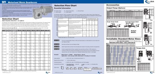
Motorised <strong>Worm</strong> <strong>Gearboxes</strong><strong>SITI</strong>SPA is a leading Eurpean manufacturer of Power Transmission products with optimal quality and efficiency ensured from astate-of-the-art automated manufacturing facility.The NEW “<strong>MU</strong>” universal mount range with modular connecting flanges make installation flexibleand easy. Efficiency has also been improved through improved design of theworm gears.A rigid die cast aluminium housing provides improved strength and easycleaning in washdown and difficult environments. The excellent surface finishmakes painting unnecessary.All <strong>MU</strong> units are supplied filled with synthetic oil for the lifetime of the gearbox.A comprehensive range of motors is available - 3 ph and 1 ph ACplus DC motors.Selection ChartQuick Gearbox Selection - at a glanceThe Selection Chart has been prepared for reliable selection under general conditions and requirements. The selection chartbelow provides an at-a-glance selection with service factors as stated. For more detailed selection according to specificapplication and duty, the Selection Flow Chart on the next page should be followed. (Where the application is foot mounted with achain drive or similar, or for arduous applications, please check with the <strong>Maud</strong> <strong>Kirk</strong> Technical Department to confirm overhung load ratings).Based on 4 pole motors @ 1400 rpm. sf * - for correct service factor for the application, please refer to next pageMotor indicated is based on standard frame size suitable. Other frame size can also be considered for alternative service factor.Ratio n 1n 2<strong>MU</strong> 30 <strong>MU</strong> 40 <strong>MU</strong> 50 <strong>MU</strong> 63 <strong>MU</strong> 75 <strong>MU</strong> 90 <strong>MU</strong> 110kW0.37 0.75 1.505280 M2(Nm)112346sf *> 3 > 32.9kW 0.18 0.37 0.75 1.5 3.0 4.0 7.507.5 187 M2(Nm) 8 16 33 68 136 185 347sf * 2 2.7 2.3 1.7 1.7 2 1.7kW 0.18 0.37 0.75 1.5 3.0 4.0 7.5010 140 M2(Nm) 10 22 44 89 180 244 456sf * 1.8 2.1 1.7 1.6 1.3 1.5 1.3kW 0.18 0.37 0.55 1.1 2.2 3.0 5.515 93 M2(Nm) 14 31 47 93 193 265 485sf * 1.3 1.5 1.6 1.5 1.2 1.4 1.3kW 0.12 0.25 0.55 0.75 1.5 2.2 4.020 70 M2(Nm) 12 26 60 83 169 254 464sf * 1.5 1.6 1.3 1.6 1.4 1.6 1.5kW 0.09 0.25 0.37 0.75 1.1 2.2 3.025 56 M2(Nm) 11 32 48 100 150 310 430sf * 1.7 1.2 1.5 1.2 1.4 1.2 1.4kW 0.09 0.25 0.37 0.75 1.1 2.2 3.030 47 M2(Nm 12 35 56 114 172 354 486sf * 1.8 1.2 1.5 1.3 1.4 1.3 1.4kW 0.09 0.18 0.25 0.55 0.75 1.5 2.240 35 M2(Nm) 16 33 48 106 148 307 4681400sf * 1.2 1.4 1.8 1.3 1.7 1.4 1.6kW 0.09 0.12 0.25 0.37 0.75 1.1 2.250 28 M2(Nm) 19 25 54 84 177 272 563sf * 1 1.7 1.4 1.7 1.3 1.4 1.2kW 0.09 0.12 0.25 0.37 0.55 1.1 1.560 23 M2(Nm) 18 29 61 94 146 311 443sf * 0.94 1.3 1.2 1.5 1.5 1.2 1.4kW0.12 0.18 0.25 0.55 0.751.17020 M2(Nm)294669164 229368sf *1.3 1.41.71.3 1.51.6kW 0.09 0.12 0.18 0.25 0.37 0.55 1.180 18 M2(Nm) 27 35 53 78 122 189 401sf * < 1 1 1.3 1.6 1.6 1.6 1.4kW0.12 0.12 0.25 0.37 0.550.7510014 M2(Nm)404188142 224323sf *111.61.2 1.31.5Weight. Kgs ~ 1.6 ~ 2 ~ 3 ~ 5 ~ 8 ~ 13 ~ 19n 1= Input rpm, n 1= output rpm, kW = Input Motor Power, M2 (Nm) = Output torque in Nm, sf = Service factor.© MKM February 2010Selection Flow ChartEssential InformationkW = Motor Power M 2= Output Torque (Nm) s f= Service Factorn 1= Motor Speed n 2= Output SpeedThe following “Selection Chart” is intended for basic selection of a gearbox based on Motor Power, Output Speed andService Factor stated. IT IS IMPORTANT TO APPLY THE CORRECT SERVICE FACTOR ACCORDING TO APPLICATION -see below for examples of different applications and their associated Service Factors.LIGHT DUTYMEDIUM DUTYHEAVY DUTYSTEP 1STEP 2STEP 3STEP 4Load classification ApplicationStart/h Average operating hours per dayEasy starting, smooth operation,small masses to be accelerated.Starting with moderate loads, uneven operatingconditions, medium size masses to beaccelerated.Uneven operation, heavy loads, largermasses to be acceleratedMultiply table figures by 1.12 for brake motors© MKM February 2010Centrifugl pumps • Belt conveyors with uniformlydistributed load • Bottling machines • Auxiliary controls ofmachine tools • Rotary gear pumps • Fans• Power generatorBelt conveyors with varied load with transfer of bridge trucks forlight duty • Levelling machines • Shakers and mixers for liquidswith variable density and viscosity • Machines for the foodindustry (kneading troughs, mincing machines, slicing machines,etc) • Sifting machines for sand gravel • Textile industry machines• Cranes, hoists, goods lifts.Machinery for bricks, tiles and clay • Kneaders • Compressorsand alternate pumps with 1 or more cylinders • MillingMachines • Lifting winches with buckets • Rotating furnaces• Heavy fans for mining purposes • Conveyors with violentjerks • Mixers • Concrete Mixers • Machine Tools• Planing Kinds • Alternating saws.