Operator's Manual - Sirona - Technical Documentation
Operator's Manual - Sirona - Technical Documentation
Operator's Manual - Sirona - Technical Documentation

Create successful ePaper yourself
Turn your PDF publications into a flip-book with our unique Google optimized e-Paper software.
kÉï=~ë=çÑW==MQKOMNN`bob`=PaléÉê~íçêDë=j~åì~äpçÑíï~êÉ=îÉêëáçå=PKUubåÖäáëÜ
Table of contents<strong>Sirona</strong> Dental Systems GmbH<strong>Operator's</strong> <strong>Manual</strong>Table of contents1 Introduction............................................................................................................... 121.1 Dear Customer,............................................................................................. 121.2 Copyright and trademark............................................................................... 121.3 General ......................................................................................................... 131.3.1 CEREC 3D software .......................................................................... 131.3.2 Master Mode option ........................................................................... 131.4 General information....................................................................................... 131.4.1 Structure of the documents................................................................ 141.4.1.1Conventions ....................................................................................... 151.4.1.2Formats of the manual ....................................................................... 152 General safety information ....................................................................................... 163 Software ................................................................................................................... 173.1 CEREC Biogeneric........................................................................................ 173.2 Installing the software ................................................................................... 173.3 Downloading the software to the milling unit................................................. 183.4 Uninstalling the software ............................................................................... 183.5 Copy protection (softguard dongle)............................................................... 193.5.1 Introduction ........................................................................................ 193.5.2 Softguard dongle................................................................................ 193.5.3 Connecting the softguard dongle ....................................................... 193.5.4 Without softguard dongles ................................................................. 203.6 Starting the software ..................................................................................... 204 User interface of the CEREC 3D software ............................................................... 214.1 Tool bar of the CEREC 3D software ............................................................. 214.2 Menu bar of the CEREC 3D software ........................................................... 224.2.1 Restoration menu in the CEREC 3D mode........................................ 224.2.2 Settings menu in the CEREC 3D mode ............................................. 234.2.3 Window menu in the CEREC 3D mode ............................................. 254.2.4 "?" menu in the CEREC 3D mode...................................................... 254.3 Toolbox window ............................................................................................ 264.3.1 Introduction ........................................................................................ 264.3.2 Showing/hiding contact surfaces........................................................ 2659 56 458 D 33442 D 3344.208.05.14.02 04.2011
<strong>Sirona</strong> Dental Systems GmbH<strong>Operator's</strong> <strong>Manual</strong>4.4 Note: 3D Preview ......................................................................................... 265 User interface in Master Mode ................................................................................ 275.1 Description of the user interface................................................................... 275.2 Tool bar ........................................................................................................ 285.3 View window................................................................................................. 295.3.1 Introduction ....................................................................................... 295.3.2 Standard views.................................................................................. 305.3.3 Zoom tool .......................................................................................... 305.3.4 Showing/hiding the neighboring teeth ............................................... 315.3.5 Showing/hiding the contact to the neighboring tooth (Contact)......... 315.3.6 Cut tool.............................................................................................. 325.3.7 Showing/hiding the occlusion/articulation ......................................... 325.3.8 Show/hide antagonist........................................................................ 335.3.8.1Interocclusal clearance ..................................................................... 345.3.8.2Antagonist ......................................................................................... 345.3.8.3Antagonist surface ............................................................................ 355.3.8.4Tools subgroup ................................................................................. 365.4 Design window ............................................................................................. 375.4.1 Editing tool (Edit)............................................................................... 375.4.1.1Editing a construction line ................................................................. 385.4.2 Form tool (Form) ............................................................................... 395.4.2.1Changing the size of the layer to be applied ..................................... 395.4.3 Wax drop (Drop)................................................................................ 405.4.3.1Modifying the wax drop size.............................................................. 405.4.3.2Applying material............................................................................... 415.4.3.3Removing material ............................................................................ 415.4.3.4Blending material .............................................................................. 415.4.4 Scaling tool (Scale) ........................................................................... 415.4.5 Shaping tool (Shape) ........................................................................ 435.4.5.1Applying material along an open line ................................................ 445.4.5.2Applying material inside a closed area.............................................. 445.4.5.3Smoothing an area............................................................................ 455.4.6 Positioning tool (Position).................................................................. 455.4.7 Rotation tool (Rotate) ........................................................................ 465.5 Status bar ..................................................................................................... 475.6 Design window ............................................................................................. 475.6.1 Design window (3D viewer)............................................................... 47båÖäáëÜ59 56 458 D 3344D 3344.208.05.14.02 04.2011 3
Table of contents<strong>Sirona</strong> Dental Systems GmbH<strong>Operator's</strong> <strong>Manual</strong>5.6.2 Scale .................................................................................................. 485.6.3 Coordinate system ............................................................................. 485.7 Menu bar ....................................................................................................... 485.7.1 Restoration menu............................................................................... 495.7.1.1Creating a restoration......................................................................... 505.7.1.2Loading a restoration ......................................................................... 515.7.1.3Deleting a restoration......................................................................... 525.7.1.4Exporting a restoration or scan data .................................................. 525.7.1.5Importing a restoration or scan data .................................................. 535.7.1.6Administering patient data.................................................................. 545.7.1.7Sending a restoration......................................................................... 555.7.2 Design menu...................................................................................... 565.7.2.1Change............................................................................................... 565.7.2.2Quadrant ............................................................................................ 575.7.2.3Pre-positioning tool ............................................................................ 575.7.2.4Centering............................................................................................ 585.7.2.5Insertion axis...................................................................................... 595.7.2.6Correcting an optical impression........................................................ 595.7.3 Settings menu .................................................................................... 595.7.3.1Parameters......................................................................................... 595.7.3.2Instruments ........................................................................................ 645.7.3.3Configuration...................................................................................... 665.7.3.4Calibration.......................................................................................... 735.7.4 Window menu .................................................................................... 745.7.4.1Display options................................................................................... 745.7.4.2Image catalog..................................................................................... 755.7.4.33D Preview......................................................................................... 755.7.4.4Cursor ................................................................................................ 755.7.4.5Distance ............................................................................................. 755.7.5 “?” menu............................................................................................. 765.7.5.1Help (online help)............................................................................... 765.7.5.2Info Options........................................................................................ 765.7.5.3Softguard info..................................................................................... 765.7.5.4Info on the program............................................................................ 776 Optical impression.................................................................................................... 786.1 Optical impressions with the CEREC Bluecam............................................. 786.1.1 Acquisition control.............................................................................. 786.1.2 Single optical impression ................................................................... 7959 56 458 D 33444 D 3344.208.05.14.02 04.2011
<strong>Sirona</strong> Dental Systems GmbH<strong>Operator's</strong> <strong>Manual</strong>6.1.3 Supplementary optical impressions .................................................. 816.1.4 Angled optical impressions ............................................................... 826.1.5 Supplementary and angled optical impressions................................ 826.1.6 Optical impressions for quadrant restoration .................................... 836.1.7 Acquiring end teeth ........................................................................... 836.1.8 Acquiring the antagonist.................................................................... 836.1.9 Veneer images .................................................................................. 846.1.10 Acquiring bridge preparations ........................................................... 846.1.11 Take casting...................................................................................... 846.2 Optical impressions with the scanner........................................................... 856.2.1 General information........................................................................... 856.2.2 15° scanning technique..................................................................... 866.2.3 45° scanning technique..................................................................... 866.2.4 Crown framework scanning technique .............................................. 876.2.5 15° scanning technique for quadrant restoration .............................. 876.2.6 Scanning antagonists........................................................................ 876.2.7 Scanning an occlusion ...................................................................... 886.3 Image fields .................................................................................................. 896.3.1 Image field of the preparation ........................................................... 896.3.2 Image field of the occlusion............................................................... 896.3.3 Image field of the buccal image ........................................................ 906.3.4 Image field of the antagonists ........................................................... 906.3.5 Image field of the articulation ............................................................ 906.4 Image catalog............................................................................................... 906.4.1 General information........................................................................... 906.4.2 Opening the image catalog ............................................................... 916.4.3 Design of the image catalog.............................................................. 916.4.4 Redefining the reference optical impression ..................................... 926.4.5 Active region (only with integrated scanner) ..................................... 936.4.6 Zooming in ........................................................................................ 936.4.7 Changing the assignment ................................................................. 936.4.8 Within an image field (inEos) ............................................................ 936.4.9 Deleting images ................................................................................ 936.4.10 Opening the recycle bin .................................................................... 946.4.11 "Puzzle" dialog box for top view image (inEos)................................. 946.4.12 Rotational image (inEos)................................................................... 946.4.13 Displaying the height image .............................................................. 946.4.14 Closing the image catalog................................................................. 94båÖäáëÜ59 56 458 D 3344D 3344.208.05.14.02 04.2011 5
Table of contents<strong>Sirona</strong> Dental Systems GmbH<strong>Operator's</strong> <strong>Manual</strong>6.5 3D Preview.................................................................................................... 946.5.1 General information............................................................................ 946.5.2 Opening the 3D Preview .................................................................... 946.5.3 Design of the 3D Preview................................................................... 956.5.4 Symbol for reference optical impression............................................ 966.5.5 Numbering of optical impressions...................................................... 966.5.6 Passive folder..................................................................................... 966.5.7 Copying/moving optical impressions.................................................. 966.5.8 Displaying the date/time in the intensity image.................................. 976.5.9 Displaying the height image............................................................... 976.5.10 Zoom function in the 3D Preview ....................................................... 986.5.11 Deleting images ................................................................................. 986.5.12 Opening the recycle bin ..................................................................... 986.5.13 Closing the 3D Preview...................................................................... 996.5.14 Discarding initial, unsuitable optical impressions............................... 996.6 Model calculation .......................................................................................... 1006.6.1 <strong>Manual</strong> Correlation............................................................................. 1016.6.2 Occlusal contact points ...................................................................... 1036.6.3 Checking the model ........................................................................... 1046.6.4 General information............................................................................ 1047 Design ...................................................................................................................... 1057.1 Trimming the preparation .............................................................................. 1057.2 Trimming the antagonist................................................................................ 1067.3 Entering the preparation margin.................................................................... 1077.3.1 General information............................................................................ 1077.3.2 Entering the preparation margin......................................................... 1087.3.3 Entering a preparation margin with unclear edges............................. 1097.4 Redefining the insertion axis ......................................................................... 1097.4.1 Preparing the right insertion axis........................................................ 1107.4.2 Redefining the insertion axis.............................................................. 1117.5 Deleting and correcting image regions in image fields.................................. 1127.5.1 Example 1: Removing a powder spot ................................................ 1127.5.2 Example 2: Deleting disturbing image regions................................... 1138 Milling ....................................................................................................................... 1148.1 Milling preview............................................................................................... 1148.1.1 Milling unit selection........................................................................... 11459 56 458 D 33446 D 3344.208.05.14.02 04.2011
<strong>Sirona</strong> Dental Systems GmbH<strong>Operator's</strong> <strong>Manual</strong>8.1.2 Block visualization............................................................................. 1158.1.3 Change of sprue location .................................................................. 1158.1.4 Positioning the restoration in a multicolored block ............................ 1168.2 Starting the milling process .......................................................................... 1168.3 Fast grinding................................................................................................. 1199 Managing/archiving data ......................................................................................... 1209.1 Saving regularly............................................................................................ 1209.2 Connect database ........................................................................................ 1209.3 Database import ........................................................................................... 1209.4 Database export ........................................................................................... 1209.5 Restoration files............................................................................................ 1209.6 Consistency check ....................................................................................... 12110 Restoration types and design techniques................................................................ 12210.1 Selecting a suitable design procedure ......................................................... 12210.2 Overview of the restoration types and design techniques............................ 12310.3 Biogeneric .................................................................................................... 12510.3.1 Introduction ....................................................................................... 12510.3.2 Design example of MOD inlay with lingual extension for tooth 27 .... 12510.3.2.1Creating a new restoration .............................................................. 12510.3.2.2Acquiring the preparation ................................................................ 12510.3.2.3Displaying the 3D representation .................................................... 12610.3.2.4Hiding image regions....................................................................... 12610.3.2.5Entering the preparation margin...................................................... 12710.3.2.6Editing the restoration ..................................................................... 12710.3.2.7Examining the milling preview ......................................................... 12910.3.2.8Milling .............................................................................................. 12910.3.3 Design example for MOD inlay with antagonist image on tooth 16... 12910.3.3.1Creating a new restoration .............................................................. 12910.3.3.2Acquiring the preparation ................................................................ 13010.3.3.3Acquiring the antagonist.................................................................. 13010.3.3.4Displaying the 3D representation .................................................... 13010.3.3.5Hiding image regions....................................................................... 13110.3.3.6Trimming the antagonist.................................................................. 13110.3.3.7Entering the preparation margin...................................................... 13210.3.3.8Making a proximal contact............................................................... 13310.3.3.9Examining the milling preview ......................................................... 133båÖäáëÜ59 56 458 D 3344D 3344.208.05.14.02 04.2011 7
Table of contents<strong>Sirona</strong> Dental Systems GmbH<strong>Operator's</strong> <strong>Manual</strong>10.3.3.10Milling ............................................................................................. 13310.3.4 Design example of partial crown with antagonist image for tooth 17. 13410.3.4.1Creating a new restoration ............................................................... 13410.3.4.2Acquiring the preparation ................................................................. 13410.3.4.3Acquiring the antagonist................................................................... 13410.3.4.4Displaying the 3D representation ..................................................... 13510.3.4.5Hiding image regions ....................................................................... 13510.3.4.6Trimming the antagonist................................................................... 13610.3.4.7Entering the preparation margin....................................................... 13610.3.4.8Examining the milling preview.......................................................... 13810.3.4.9Milling ............................................................................................... 13810.3.5 Design example of crown with antagonist image for tooth 47............ 13810.3.5.1Creating a new restoration ............................................................... 13810.3.5.2Acquiring the preparation ................................................................. 13910.3.5.3Acquiring the antagonist................................................................... 13910.3.5.4Displaying the 3D representation ..................................................... 13910.3.5.5Hiding image regions ....................................................................... 14010.3.5.6Trimming the antagonist................................................................... 14010.3.5.7Entering the preparation margin....................................................... 14010.3.5.8Performing the design ...................................................................... 14110.3.5.9Examining the milling preview.......................................................... 14210.3.5.10Milling ............................................................................................. 14210.3.6 Design example of articulation (in Master Mode only) ....................... 14210.3.6.1Creating a new restoration ............................................................... 14210.3.6.2Acquiring the preparation ................................................................. 14310.3.6.3Acquiring the antagonist................................................................... 14310.3.6.4Acquiring the dynamic occlusion impression ................................... 14310.3.6.5Hiding image regions ....................................................................... 14310.3.6.6Trimming the antagonist................................................................... 14310.3.6.7Entering the preparation margin....................................................... 14310.3.6.8Performing the design ...................................................................... 14410.3.6.9Examining the milling preview.......................................................... 14410.3.6.10Milling ............................................................................................. 14410.3.7 Provisional bridges (in the Master Mode only)................................... 14410.3.7.1Creating a new restoration ............................................................... 14410.3.7.2Acquiring optical impressions........................................................... 14410.3.7.3Trimming the preparation ................................................................. 14410.3.7.4Trimming the antagonist................................................................... 14510.3.7.5Entering the preparation margin and base lines .............................. 14559 56 458 D 33448 D 3344.208.05.14.02 04.2011
<strong>Sirona</strong> Dental Systems GmbH<strong>Operator's</strong> <strong>Manual</strong>10.3.7.6Designing a bridge .......................................................................... 14510.3.7.7Examining the milling preview ......................................................... 14610.3.7.8Milling .............................................................................................. 14610.4 Correlation (in Master Mode only) ................................................................ 14710.4.1 General information........................................................................... 14710.4.2 <strong>Manual</strong> Correlation............................................................................ 14810.4.3 Design example for tooth 16 with extensive fissure caries and 149proximal caries on both sides10.4.3.1Creating a new restoration .............................................................. 14910.4.3.2Acquiring the occlusion ................................................................... 14910.4.3.3Acquiring the preparation ................................................................ 15010.4.3.4Hiding image regions....................................................................... 15110.4.3.5Entering the preparation margin...................................................... 15110.4.3.6Adapting the copying line ................................................................ 15210.4.3.7Editing the restoration ..................................................................... 15210.4.3.8Examining the milling preview ......................................................... 15410.4.3.9Milling .............................................................................................. 15410.4.4 Design example of crown for tooth 26............................................... 15410.4.4.1Creating a new restoration .............................................................. 15410.4.4.2Acquiring the occlusion ................................................................... 15410.4.4.3Acquiring the preparation ................................................................ 15510.4.4.4Hiding image regions....................................................................... 15510.4.4.5Entering the preparation margin...................................................... 15610.4.4.6Accepting a copying line.................................................................. 15610.4.4.7Editing the restoration ..................................................................... 15710.4.4.8Examining the milling preview ......................................................... 15810.4.4.9Milling .............................................................................................. 15810.5 Biogeneric reference (only in Master Mode) ................................................ 15810.6 Quadrant restoration (in Master Mode only)................................................. 15910.6.1 Design example for teeth 14 to 17 .................................................... 15910.6.1.1Preparing, drying and powdering .................................................... 15910.6.1.2Acquiring tooth 16 ........................................................................... 15910.6.1.3Acquiring supplementary optical impressions ................................. 16010.6.1.4Tooth 16: Creating the restoration................................................... 16010.6.1.5Tooth 15: Creating the restoration................................................... 16010.6.1.6Tooth 14: Creating the restoration................................................... 16110.6.1.7Tooth 17: Creating the restoration................................................... 16110.6.1.8All restorations................................................................................. 162båÖäáëÜ59 56 458 D 3344D 3344.208.05.14.02 04.2011 9
Table of contents<strong>Sirona</strong> Dental Systems GmbH<strong>Operator's</strong> <strong>Manual</strong>11 Adhesive bonding of restorations ............................................................................. 16312 Messages ................................................................................................................. 16412.1 Information .................................................................................................... 16412.2 Warnings ....................................................................................................... 16412.3 Error messages............................................................................................. 16412.3.1 Self-explanatory error messages ....................................................... 16512.3.2 Two-stage errors................................................................................ 16512.3.3 Errors in connection with determining or managing construction lines 16512.3.4 Errors in the reconstruction of the restoration.................................... 16612.3.5 System errors..................................................................................... 16612.3.6 Memory allocation errors.................................................................... 16713 Link to Practice Administration ................................................................................. 16813.1 Parameter interface....................................................................................... 16813.1.1 Patient data as parameter list ............................................................ 16813.1.2 Parameter interface: CerPI.exe.......................................................... 16813.1.3 Generating or preselecting patients ................................................... 16813.2 SLIDA interface ............................................................................................. 16914 Tips and Tricks ......................................................................................................... 17014.1 VITA CAD-Temp multiColor .......................................................................... 17014.2 Screenshot / TIF image................................................................................. 17014.3 Importing CEREC Connect files into the CEREC 3D software ..................... 17114.4 <strong>Technical</strong> notes ............................................................................................. 17114.4.1 No optical impressions can be taken while a DVD film is being played 171back14.4.2 Softguard dongle................................................................................ 17114.4.3 Problems during communication with the milling unit ........................ 17214.4.3.1Examples with CEREC 3 acquisition unit connected ....................... 17214.4.3.2For PC/notebook .............................................................................. 17214.4.4 No sleep mode during the milling process ......................................... 17314.4.5 Changing the font size ....................................................................... 17314.4.6 Screen saver...................................................................................... 17314.4.7 Task Manager .................................................................................... 17314.4.8 Correlation quality .............................................................................. 17314.5 Service program............................................................................................ 17414.6 Frequently Asked Questions ......................................................................... 17459 56 458 D 334410 D 3344.208.05.14.02 04.2011
<strong>Sirona</strong> Dental Systems GmbH<strong>Operator's</strong> <strong>Manual</strong>14.6.1 Database connection ........................................................................ 17414.6.2 Minimizing the program..................................................................... 17414.6.3 Blurred optical impressions ............................................................... 17414.6.4 Additional software on the CEREC 3D DVD ..................................... 175Glossary .................................................................................................................. 176Index........................................................................................................................ 178båÖäáëÜ59 56 458 D 3344D 3344.208.05.14.02 04.2011 11
IntroductionDear Customer,<strong>Sirona</strong> Dental Systems GmbH<strong>Operator's</strong> <strong>Manual</strong>1 Introduction1.1 Dear Customer,General descriptionThank you for purchasing your CEREC 3D software from <strong>Sirona</strong>.In connection with CEREC 3 / CEREC MC XL, this software enables you toproduce dental restorations, e.g. from ceramic material with a natural appearance(CEramic REConstruction).Improper use and handling can create hazards and cause damage. Therefore,please read and carefully follow this manual and the relevant operatinginstructions. always keep them within easy reach.In order to master the system safely, you should train on the exercise modelusing the described examples.To prevent personal injury or material damage it is important to observe all safetyinformation.To safeguard your warranty claims, please complete the attached InstallationReport / Warranty Passport when the system is handed over and send it tothe indicated fax number.Your TeamYourCEREC 3D Team1.2 Copyright and trademarkCopyrightTrademarks© <strong>Sirona</strong> Dental Systems GmbH 2010. All rights reserved.The information contained in this manual may be changed without notice.The software and all related documentation are protected by copyright. Youmust therefore handle it in the same way as any other protected material.Anyone who copies this software or this manual to magnetic tape, floppy diskor any other medium for any purpose other than his own personal use withoutthe written permission of <strong>Sirona</strong> Dental Systems will be liable to prosecution.Microsoft ® and Windows 7 ® are registered trademarks.Windows TM is a trademark of Microsoft Corporation.Windows Vista TM is a trademark of Microsoft Corporation.All other trademarks are the property of their respective holders.Components of other manufacturersThis software contains components produced by the following manufacturers:Zlib:© 1995-2002 Jean-loup Gailly, Mark Adler and Greg RoelofsPaintLib:© 1996-2000 Ulrich von ZadowLibTiff:© 1988-1997 Sam Leffler© 1991-1997 Silicon Graphics, Inc.LeadTools:© 1991-2000 LEAD Technologies, Inc.59 56 458 D 334412 D 3344.208.05.14.02 04.2011
<strong>Sirona</strong> Dental Systems GmbH Introduction<strong>Operator's</strong> <strong>Manual</strong>1.3 GeneralIn order to effectively address the needs of new and experienced CERECusers, the software has been split into two parts - CEREC 3D mode and "MasterMode".1.3.1 CEREC 3D softwareThe CEREC 3D software has been optimized for easy and efficient design ofinlays, onlays and crowns with the aid of the "Biogeneric" design techniquewith or without antagonist.Changeover to the "Master Mode" is advisable only for users who have masteredall the basic procedures of the CEREC 3D method.A description of these functions can be found under "User interface of the CE-REC 3D software" [ ➙ 21].1.3.2 Master Mode optionYou can select the "Master Mode" by selecting the menu option "Settings" /"Master Mode" . This displays all functions of the software.A description of these functions can be found under "User interface in MasterMode".båÖäáëÜ1.4 General informationCAUTIONBe sure to observe all warnings!Please observe the warning and safety information provided to prevent personalinjury and material damage. Any such information is highlighted by asignal word, i.e. WARNING, CAUTION or NOTE.Please read this document completely and follow the instructions exactly. Youshould always keep it within reach.Original language of the present document: German.59 56 458 D 3344D 3344.208.05.14.02 04.2011 13
IntroductionGeneral information<strong>Sirona</strong> Dental Systems GmbH<strong>Operator's</strong> <strong>Manual</strong>1.4.1 Structure of the documentsemptyStructure of the documentsThe symbols and character formats used in the present manual have the followingmeaning:WARNINGIdentifies warnings where a medium risk of injury to persons exists if theyare not observed.CAUTIONIdentifies safety information where the following hazards exist if they are notobserved: Slight risk of injury to persons, risk of property damage or damageto the product.NOTICEAssistanceIdentifies additional information, hints and tips.✔ Prerequisite➢ Actionor➢ 1., 2., …Requests you to do something.ResultSee chapter "Structure of thedocuments [ ➙ 14]"● List Identifies a list.“Text between quotationmarks“Identifies a reference to another text passage.Identifies commands, menu items or quotations.59 56 458 D 334414 D 3344.208.05.14.02 04.2011
<strong>Sirona</strong> Dental Systems GmbH Introduction<strong>Operator's</strong> <strong>Manual</strong>1.4.1.1 ConventionsExampleClickingDouble-clickingMoving the mousein one directionSeizing a pointFor impressions acquiredwith 3D camera:Actuate footswitch"Ctrl+N"1.4.1.2 Formats of the manualMeaningPressing once and releasing the left mouse button orthe left trackball button on the acquisition unit (or footswitch).Pressing twice quickly in succession and releasing theleft mouse button or the left trackball button on the acquisitionunit (or foot switch).On the acquisition unit: Moving the trackball in the correspondingdirection.Pressing the left mouse button (left trackball button onthe acquisition unit) and keeping it pressed.The same function as: Pressing the left trackball buttonon the acquisition unit or the left mouse button.On the keyboard: Press the Ctrl and N keys simultaneously.båÖäáëÜHTMLThe <strong>Operator's</strong> <strong>Manual</strong> is available on the supplied program DVD in html format.This format is screen-oriented and is well suited for finding terms, e.g. inthe index or table of contents.You can call up this manual via the online help function.PDFThe <strong>Operator's</strong> <strong>Manual</strong> is available on the supplied program DVD in pdf format.This format is page-oriented and is well suited for printing out the desired pages.59 56 458 D 3344D 3344.208.05.14.02 04.2011 15
General safety information<strong>Sirona</strong> Dental Systems GmbH<strong>Operator's</strong> <strong>Manual</strong>2 General safety informationemptyOnly use original softwareOnly use original software or software which has been released by <strong>Sirona</strong>. Toproduce restorations, manipulated and non-released software componentsmust not be used.Software and software components must not be installed using incorrect data.Please also ensure that each installed component has been granted approvalin its country. Contact your dealer for more information.emptyRestoration to be checked by trained personnelEach restoration which is performed with this software must be checked forsuitability by a trained person (e.g. dental technician or dentist).emptyFor the USA onlyFor the USA onlyCAUTION: Federal Law (USA) restricts sale of this device to or on the orderof a physician, dentist, or licensed practitioner.59 56 458 D 334416 D 3344.208.05.14.02 04.2011
<strong>Sirona</strong> Dental Systems GmbH Software<strong>Operator's</strong> <strong>Manual</strong>3 Software3.1 CEREC BiogenericCEREC Biogeneric is the first method which is able to reconstruct lifelike occlusalsurfaces. On the basis of the features of a patient's single intact tooth,the program extrapolates the naturally created morphology of other teeth. Thebiogeneric occlusal design functions for all single tooth restorations and fullyanatomic bridges.Currently, all occlusal design approaches are based on dental libraries anddatabases containing data records of various standard teeth. ConventionalCAD/CAM programs retrieve a matching tooth from the archive, and then generatea design proposal for the given clinical situation. The user then manuallyedits and adapts this proposal. The biogeneric occlusal design is toreplace the “dental database” design procedure applied in previous CERECsoftware versions. It will now be possible to create crowns, inlays, onlays, veneers,and anatomically sized bridges in a fully automated manner. The reconstructioncan be based on any intact patient tooth from the same type, i.e.posterior tooth or anterior tooth. The often time-consuming process of manuallyadjusting the tooth to the clinical situation is now virtually a thing of thepast. Moreover, due to the standardized and largely automated routines, thenew software is easy to get to grips with and use.båÖäáëÜ3.2 Installing the softwareNOTICEAdministrator rightsInstallation only with administrator rightsYou must have administrator rights on the PC on which you want to installthe software!Installing the softwareInstallation procedure✔ The PC is powered up and all programs are terminated.1. Insert the DVD in the CD/DVD drive. The setup program starts automatically.2. If this is not the case, run the "Setup.exe" file in the root directory of theDVD.3. Select the language of the installation and click the button marked "OK". The installation wizard opens.4. Click the "Next" button. The license agreement is shown.5. Accept the license agreement with the "Yes" button. The program continues the installation routine.Standard installationSelecting the standard installation 1. Click the button marked "Standard Installation".NOTICEInstalling DirectXIf DirectX is not yet installed on your computer, it will be installed now. Acceptthe license agreement and decide whether the computer is to be restartednow or later.59 56 458 D 3344D 3344.208.05.14.02 04.2011 17
SoftwareDownloading the software to the milling unit<strong>Sirona</strong> Dental Systems GmbH<strong>Operator's</strong> <strong>Manual</strong>2. To complete the installation, you can register to receive current informationon software updates and/or have the "ReadMe"file displayed. Thisfile contains the latest information on the software.Select or deselect the corresponding checkbox.3. Click the button marked "Finish".4. Decide whether the computer should be restarted now or later and clickthe button marked "Finish".Notes on the software versionInformation about this software versionYou can load a restoration made with an earlier software version with this versionas well. However, once this restoration has been saved with the currentsoftware version, it can no longer be loaded with the earlier software version.The restoration can be saved according to the following procedures:● By selecting "Restoration" / "Save" .● By selecting "Restoration" / "Save as…" .● Automatically, by confirming the image catalog with the "Next"icon.● Automatically, by pressing the "Mill"icon.● Automatically, during virtual seating ("Design" / "Quadrant…".)3.3 Downloading the software to the milling unitCAUTIONTransferring the milling programFollowing installation of the new software, the new milling program must betransferred to the milling unit.emptyCEREC 3 milling unitCEREC 3 milling unit✔ The new software is installed on the PC.➢ Transfer the new milling program to the milling unit as described in theOperating Instructions for the milling unit.emptyCEREC/inLab MC XLCEREC MC XLThe new milling program is automatically transferred to the milling unit.3.4 Uninstalling the software✔ The program is closed.1. Click "Start" / "Programs" / "CEREC 3D" / "Deinstallation"to uninstall thesoftware. During the uninstall procedure, you will be asked whether you wantto delete the patient data or the entries in the registration database(e.g. the calibration data).2. According to how you decide, click the button marked "Yes" or "No". The software is uninstalled.59 56 458 D 334418 D 3344.208.05.14.02 04.2011
<strong>Sirona</strong> Dental Systems GmbH Software<strong>Operator's</strong> <strong>Manual</strong>3.5 Copy protection (softguard dongle)3.5.1 IntroductionWhether a given restoration may be milled depends on the softguard dongleconnectedand the identifier of the milling unit used.3.5.2 Softguard dongleHeadingSoftguard dongleThe following softguard dongles are available:CEREC 3D●CEREC 3D (for inlays, onlays, crowns and veneers)AK x CEREC●AK x 1 (only in conjunction with the inLab 3D software).Explanation of AKAK = Activation KeyDebiting from AK xThe AK x softguard dongles have a counter that deducts one unit for each millingoperation:Overview of debitingRestorationInlay, onlay,occlusal inlayCrownVeneerCrown frameworkWax-up, Bridge correlationBridge framework, anatomicalbridgeAbutmentDebit from AK x1 unit per restoration1 unit per restoration1 unit per restoration1 unit per restoration1 unit per milling operation1 unit per bridge element1 unit per bridge abutment1 unit per restorationbåÖäáëÜ3.5.3 Connecting the softguard dongleemptyAKx✔ The PC must have a parallel port.1. Connect the softguard dongle to the parallel port of the PC.2. You may then connect further softguard dongles or e.g. a printer to thissoftguard dongle.empty1. x = Remaining number of units (that can be milled with this activation key)59 56 458 D 3344D 3344.208.05.14.02 04.2011 19
SoftwareStarting the software<strong>Sirona</strong> Dental Systems GmbH<strong>Operator's</strong> <strong>Manual</strong>AK Unlimited inLab 3D or AKx USB softguard dongles✔ The PC must have a free USB port.➢Connect the AK Unlimited inLab 3D or AKx USB softguard dongle to theUSB port of the PC.3.5.4 Without softguard donglesAll restorations can be scanned, designed and saved without a softguarddongle. You need a softguard dongle for milling.3.6 Starting the softwareStarting the software✔ The CEREC 3D software is installed. The CEREC 3D button is locatedon the desktop.➢ Start the CEREC 3D software by double-clicking the CEREC 3D button.or➢ Click "Start" / "Programs" / "CEREC 3D" / "CEREC 3D".59 56 458 D 334420 D 3344.208.05.14.02 04.2011
<strong>Sirona</strong> Dental Systems GmbH User interface of the CEREC 3D software<strong>Operator's</strong> <strong>Manual</strong>4 User interface of the CEREC 3D software4.1 Tool bar of the CEREC 3D softwareemptyDescription of the iconsExplanation on the CEREC 3D mode tool barYou can show or hide the tool bar via the "Window" / "Tool bar" menu item.Inactive functions appear dimmed.●Open new restorationCreate a new restoration●Preparation cameraScan/acquire prepared tooth (preparation)●Antagonist cameraScan/acquire antagonist/registrationbåÖäáëÜNext●One design step forward (Next)Undo●One design step backward (Undo)●Start the milling processStarting the milling processToolbar handlingYou can drag the tool bar with the mouse and drop it anywhere on the screen.It can be docked at the left, right, top or bottom edge of the screen, as is usualwith Windows programs. Via "Window" / "Reset" ("Ctrl+R") it can be restoredto the position it had on delivery (left edge of screen).59 56 458 D 3344D 3344.208.05.14.02 04.2011 21
User interface of the CEREC 3D softwareMenu bar of the CEREC 3D software<strong>Sirona</strong> Dental Systems GmbH<strong>Operator's</strong> <strong>Manual</strong>4.2 Menu bar of the CEREC 3D softwareDescription of menu barThe menu bar at the top of the window allows you to select further programfunctions which cannot be accessed via the tool bars.CEREC 3D mode graphic menu barThe following menus are available in the CEREC 3D mode:● "Restoration"● "Settings"● "Window"● "?"NOTICEAlternatives to the menu barAlternatives to the menu barSome menu functions can also be activated using the shortcut keys specifiedin the menu item or the corresponding icons on the tool bar.4.2.1 Restoration menu in the CEREC 3D modeRestoration graphic menuRestoration menu in the CEREC 3D mode59 56 458 D 334422 D 3344.208.05.14.02 04.2011
<strong>Sirona</strong> Dental Systems GmbH User interface of the CEREC 3D software<strong>Operator's</strong> <strong>Manual</strong>Graphics: CEREC 3D modebåÖäáëÜLoading a restoration in the CEREC 3D modeLoading a restoration in the CEREC 3D modeIn the dialog box "Load restoration" all restorations are displayed in the CE-REC 3D mode. However, optical impressions taken in the Master mode aredimmed and can not be loaded.Reference masterA detailed description of the individual menu items can be found under "Restorationmenu".4.2.2 Settings menu in the CEREC 3D modeWith the "Settings" menu, you can adapt and change the following menuitems:● "Instruments"● "Configuration"● "Calibration"● "Master Mode"emptyInstrumentsThis menu item allows you to change worn/defective milling instruments. Alsorefer to the chapter "Changing burrs" in the Operating Instructions of the millingunit.59 56 458 D 3344D 3344.208.05.14.02 04.2011 23
User interface of the CEREC 3D softwareMenu bar of the CEREC 3D software<strong>Sirona</strong> Dental Systems GmbH<strong>Operator's</strong> <strong>Manual</strong>emptyConfigurationUnder this menu item, you can check and modify the factory-set configurations.● "Devices..."● "Options"All connected milling units can be displayed and configured under the menuitem "Settings"/"Configuration"/"Devices...".Options in the CEREC 3D modeVia the menu item "Settings"/"Configuration"/"Options" you can set the following:●●Show/hide docking bar"Automatic capture" (with CEREC Bluecam only)With CEREC BluecamWith CEREC 3 cameraThe docking bar is hidden in the 3D preview. If you move the mouse pointerto the lower part of the respective image field, the docking bar dynamically appears.If you place a check mark in front of "Hide dockbar" , the docking bar will bedisplayed permanently.Automatic acquisition (Bluecam only)For impressions acquired with the CEREC Bluecam, you can use the "Automaticcapture" option to set the sensitivity to shaking of the automatic acquisitiontechnique. The setting options are available:● "very strict"● "strict"● "standard"● "tolerant"● "very tolerant"emptyCalibrationVia the "Calibration" menu item you can...● calibrate the "3D camera",(see the chapter "Calibrating the Bluecam/3D camera" in the OperatingInstructions for the acquisition unit).59 56 458 D 334424 D 3344.208.05.14.02 04.2011
<strong>Sirona</strong> Dental Systems GmbH User interface of the CEREC 3D software<strong>Operator's</strong> <strong>Manual</strong>NOTICECalibrating the Bluecam/3D cameraIn order to calibrate the Bluecam/3D camera, the "Bluecam calibration set"/"3D calibration set" is required.The "Bluecam calibration set"/"3D calibration set" must not be powdered.●calibrate the "Milling unit",(see chapter on “Calibrating the milling unit” in the operating instructionsfor the milling unit).emptyMaster ModeIf you select "Settings"/"Master Mode" from the menu, all software functionsare shown.båÖäáëÜIf you select the "Settings" / "Exit Master Mode" menu item, the unit is resetto its delivery status (CEREC 3D Mode).A detailed description of the individual menu items can be found under "Settingsmenu".4.2.3 Window menu in the CEREC 3D modeRestoring the default settingsYou can restore the default setting for the display of the windows/tool bar onthe screen:"Window" / "Reset" or "Ctrl+R"4.2.4 "?" menu in the CEREC 3D modeIf the menu item "Text prompts" the next work step is described in a balloonin the status bar.A detailed description of the individual menu items can be found under ""?"menu".59 56 458 D 3344D 3344.208.05.14.02 04.2011 25
User interface of the CEREC 3D softwareToolbox window<strong>Sirona</strong> Dental Systems GmbH<strong>Operator's</strong> <strong>Manual</strong>4.3 Toolbox window4.3.1 IntroductionYou can drag the window with the mouse by grabbing its title bar and drop itat any position on the screen. Via "Window" / "Reset" ("Ctrl+R") it can be restoredto the position it had on delivery (right edge of screen).● A: Standard viewsFor a detailed description, see "Standard views" [ ➙ 30].● B: Zoom toolFor a detailed description, see "Zoom tool" [ ➙ 30].● C: Showing/hiding contact surfaces ("Contacts")For a detailed description, see "Showing/hiding contact surfaces" [ ➙ 26].● D: Form tool ("Form")For a detailed description, see "Form tool" [ ➙ 39].4.3.2 Showing/hiding contact surfacesBy clicking the button marked "Contacts" you can show/hide the contact surfacesto the neighboring teeth and to the antagonist. The neighboring teethare then hidden or shown.When the contact surfaces are shown, a color scheme with the followingmeaning appears:● blue: Clearance 0-1 mmSmaller surface – larger clearance● green: Penetration 0-50 µm● yellow: Penetration 50-100 µm● red: Penetration >100µmWith the "Form" tool, you can design the contact surfaces according to yourwishes.4.4 Note: 3D PreviewIn the 3D mode, the 3D Preview displays only the "Preparation" and "antagonist"image fields. There is no image field for occlusal impressions.59 56 458 D 334426 D 3344.208.05.14.02 04.2011
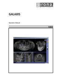
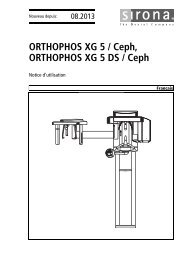
<strong>Sirona</strong> Dental Systems GmbH User interface in Master Mode<strong>Operator's</strong> <strong>Manual</strong>5 User interface in Master Mode5.1 Description of the user interfaceABCDIEFbåÖäáëÜHGMain menuCEREC 3D features a menu-controlled user interface enabling you to scanpreparations and then design and mill the required restorations.Screen displays guide you through the design process and give you a continuousoverview of which program step is currently being performed.The main menu consists of:●●●●●●●●●A: Tool barB: Menu barC: Program window title,D: View windowE: Coordinate systemF: Design windowG: Status barH: Scale (1 mm)I: Design window (3D viewer)59 56 458 D 3344D 3344.208.05.14.02 04.2011 27
User interface in Master ModeTool bar<strong>Sirona</strong> Dental Systems GmbH<strong>Operator's</strong> <strong>Manual</strong>You can show or hide the following windows/bars:● "View"● "Design"● "Tool bar"● "Status bar"5.2 Tool barExplanation on tool barYou can show or hide the tool bar via the "Window" / "Tool bar" menu item.Unavailable functions are grayed out (e.g. Occlusion in the example below).emptyDescription of the buttons●Open new restorationCreate a new restoration●Load restorationLoad restoration●Save restorationSave restoration●Preparation: camera, scanner, inEosScan/acquire prepared tooth (preparation)●Occlusion: camera, scanner, inEosScan/acquire unprepared tooth (occlusion)●ArticulationScan/acquire dynamic occlusion impression (articulation)59 56 458 D 334428 D 3344.208.05.14.02 04.2011
<strong>Sirona</strong> Dental Systems GmbH User interface in Master Mode<strong>Operator's</strong> <strong>Manual</strong>●Buccal imageAcquire a buccal optical impression●Scan/acquire antagonist/registrationAntagonist graphics: camera, scanner, inEosNext●One design step forward (Next)Undo●One design step backward (Undo)●Start the milling processStarting the milling processbåÖäáëÜ●infiniDentSend restoration to infiniDentToolbar handlingYou can drag the tool bar with the mouse and drop it anywhere on the screen.It can be docked at the left, right, top or bottom edge of the screen, as is usualwith Windows programs. Via "Window" / "Reset" ("Ctrl+R") it can be restoredto the position it had on delivery (left edge of screen).5.3 View window5.3.1 IntroductionDescriptionYou can display or hide this window via the menu item "Window"/"View" .Inactive windows appear dimmed.You can drag the window with the mouse by grabbing its title bar and drop itat any position on the screen. Via "Window" / "Reset" ("Ctrl+R") it can be restoredto the position it had on delivery (right edge of screen).59 56 458 D 3344D 3344.208.05.14.02 04.2011 29
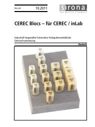
User interface in Master ModeView window<strong>Sirona</strong> Dental Systems GmbH<strong>Operator's</strong> <strong>Manual</strong>View window●●●●●●●A: Standard viewsB: Zoom toolC: Showing/hiding the neighboring teeth (Trim)D: Showing/hiding the contact to the neighboring tooth (Contact)E: Cut toolF: Showing/hiding the occlusion/articulation/gingival maskG: Show/hide antagonist5.3.2 Standard viewsThe objects in the Design window can be displayed in six predefined views byclicking the corresponding arrows:● "Mesial"● "Distal"● "Buccal" / "Labial"● "Lingual"● "Cervical"● "Occlusal" / "Incisal"When you point to one of these arrows with the mouse cursor, the direction ofthe view is indicated.When you click the arrow, the object is turned into this view.There are two ways to display the "Mesial", "Distal", "Buccal" / "Labial" and"Lingual" views:Single-clickOblique top viewDouble-click90° viewIf you have changed the display of the objects with the zoom tool, you can resetthis change by clicking on the tooth in the View window.5.3.3 Zoom toolThe objects displayed in the Design window can be zoomed in and out as follows:● step by step, by repeatedly clicking the "+" sign (zoom in) or the "-" sign(zoom out)● continuously, by pressing and holding down the "+" sign (zoom in) or the"-" sign (zoom out)59 56 458 D 334430 D 3344.208.05.14.02 04.2011
<strong>Sirona</strong> Dental Systems GmbH User interface in Master Mode<strong>Operator's</strong> <strong>Manual</strong>●●by pressing the center mouse button and moving the mouse:– forward, you zoom the 3D view in– back, you zoom the 3D view outby simultaneously pressing the left mouse button and the Shift key andmoving the mouse:– forward, you zoom the 3D view in– back, you zoom the 3D view out5.3.4 Showing/hiding the neighboring teethYou can hide the neighboring teeth by clicking the "Trim" button.For the case that parts of the neighboring teeth are disturbing during input ofthe preparation margin, trimming off the disturbing parts is possible. For thispurpose, you can hide parts of the image after image acquisition (see "Trimmingthe preparation [ ➙ 105]“).You can redisplay the neighboring teeth by clicking the "Trim" button again.NOTICEShowing and hiding with the Trim buttonIf the preparation was not trimmed, you can use the "Trim" button to showand hide the entire preparation, e.g. for editing the proximal surface of therestoration.båÖäáëÜ5.3.5 Showing/hiding the contact to the neighboring tooth (Contact)You can show or hide the contact surface to the neighboring tooth by clickingthe "Contact" button.You can click on the "Contact" button to open the "Contact Options" dialogbox. 1 .You can have the appropriate proximal contact defined automatically by clikkingthe corresponding button.NOTICEHiding the neighboring teethFor better assessment of the contact surface you can hide the neighboringteeth with the "Trim" button.If you click the "Contact" button, a color scheme with the following meaningappears on the contact surfaces:1. This option can only be used for posterior tooth crowns (not for anterior toothcrowns, veneer, etc.).59 56 458 D 3344D 3344.208.05.14.02 04.2011 31
User interface in Master ModeView window<strong>Sirona</strong> Dental Systems GmbH<strong>Operator's</strong> <strong>Manual</strong>● blue: Clearance 0-1 mmSmaller surface – larger clearance● green: Penetration 0-50 µm● yellow: Penetration 50-100 µm● red: Penetration >100µmYou can use the design tools "Scale", "Shape", "Form", and "Drop" to designthe contact surfaces according to your wishes.5.3.6 Cut toolTo open the "Cut" window, choose "Cut" or "Ctrl+C".You can place a cut plane through the restoration and preparation by clickingthe "Cut" tool. The cut plane lies parallel to the screen plane. The cut planecan be moved parallel in two ways:●●step by step, by repeatedly clicking the “+” or “-” Cut semicirclescontinuously, by keeping a semicircle pressed.CERECFor bridges, the cut surface is displayed in the status bar.Cut planeTo exit the "Cut" tool, click the highlighted "Cut" bar.Close the "Cut" window by clicking x (Close) or the "Cut" button.5.3.7 Showing/hiding the occlusion/articulationemptyOcclusionOcclusionIf an image field of the occlusion exists, you can show or hide it with the helpof this button.emptyArticulationArticulationThis function can be used only for the following:● "Restoration": "Crown"● "Design technique": "Articulation"59 56 458 D 334432 D 3344.208.05.14.02 04.2011
<strong>Sirona</strong> Dental Systems GmbH User interface in Master Mode<strong>Operator's</strong> <strong>Manual</strong>If a dynamic occlusion impression (FGP, Functionally Generated Path) exists,it can be shown or hidden with the help of this button.If you click the "Articulation" button, the 3D model of the dynamic occlusionimpression is displayed and an additional dialog box is opened with the "FitRestoration" button.Interfering_contact_FGPIf you click the "Fit Restoration" button, all of the interfering contacts of the restorationwhich "protrude out of" the FGP will be virtually milled so that theydisappear.båÖäáëÜInterfering contacts milled5.3.8 Show/hide antagonistBy clicking the button marked "Antagonist" you can show/hide the Antagonistwindow.59 56 458 D 3344D 3344.208.05.14.02 04.2011 33
User interface in Master ModeView window<strong>Sirona</strong> Dental Systems GmbH<strong>Operator's</strong> <strong>Manual</strong>Antagonist windowIn this window, under "View Options" you can activate or deactivate the following:● "Interocclusal Clearance"● "Antagonist"● "Antagonist surface"5.3.8.1 Interocclusal clearanceDescriptionWhen "Interocclusal Clearance" is activated, a color scheme with the followingmeaning of the colors appears on the restoration:Explanation of colors● blue: Clearance 0-1 mmSmaller surface – larger clearance● green: Penetration 0-50 µm● yellow: Penetration 50-100 µm●red: Penetration >100µmDesign toolsYou may use the "Scale", "Shape", "Form" or "Drop" design tools to adapt thedistance.5.3.8.2 AntagonistIf "Antagonist" is activated, the optical impression of the centric bite registrationappears above the restoration.59 56 458 D 334434 D 3344.208.05.14.02 04.2011
<strong>Sirona</strong> Dental Systems GmbH User interface in Master Mode<strong>Operator's</strong> <strong>Manual</strong>Antagonist displayedBy clicking the buttons next to "Elevate Antagonist" you can elevate or lowerthe registration. You obtain a better view onto the occlusal surface by elevatingthe antagonist.You can view the restoration from all directions and adapt it with the "Design"tools.båÖäáëÜ5.3.8.3 Antagonist surfaceIf "Antagonist surface" is activated, the occlusal surface of the antagonist/registrationappears above the restoration.Antagonist surface displayedBy clicking the buttons next to "Elevate Antagonist" you can elevate or lowerthe registration. You obtain a better view onto the occlusal surface by elevatingthe antagonist.You can view the restoration from all directions and adapt it with the "Design"tools.59 56 458 D 3344D 3344.208.05.14.02 04.2011 35
User interface in Master ModeView window<strong>Sirona</strong> Dental Systems GmbH<strong>Operator's</strong> <strong>Manual</strong>5.3.8.4 Tools subgroupAntagonist windowWith the "<strong>Manual</strong> Trim" button in the "Antagonist" dialog box you can also hideimage regions at a later point in time.For posterior tooth crowns with antagonist (design technique "Biogeneric" or"Biogeneric reference"), the "Settling", "Cusp settling" and "Virtual grinding"buttons all have the same function as in the automatic crown suggestion (see"Options" in the "Settings" Chapter). You can use these functions if you havechanged the suggested crown with the "Design" tools and would like to redefinethe occlusal contacts.For inlays/onlays in the design technique "Biogeneric" with antagonist, youcan automatically set the occlusal contacts with these buttons. Automatic adaptationsto the antagonist are performed for the inlay/only initial suggestion.emptySettling buttonWith this button, the restoration is adapted to the antagonist so that the resultingcontact situation is as stable as possible. The contacts should have aslittle penetration volume as possible. The morphology of the occlusal surfaceis not changed.emptyCusp settling buttonIf the restoration features a cusp tip, the "Cusp settling" button is automaticallyenabled. This button triggers automatic adaptation of the individual cusps ofthe restoration to the antagonist. The cusps are adapted to the antagonist sothat the resulting contact situation is as stable as possible. The morphologyof the occlusal surface is changed.emptyVirtual grinding buttonThis button can be used to virtually grind the existing occlusal contacts. Thisfunction removes the red contacts down to a size that you have defined in theparameter dialog under "Occlusal contact strength".When designing inlays/onlays and crowns which are not automatically adapted,we recommend that you initially adapt the restoration to the present situationwith the "Design" tools. Then you can finalize the contact situation withthe following buttons in this order:1. "Settling"2. "Cusp settling"3. "Virtual grinding"59 56 458 D 334436 D 3344.208.05.14.02 04.2011
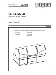
<strong>Sirona</strong> Dental Systems GmbH User interface in Master Mode<strong>Operator's</strong> <strong>Manual</strong>NOTICEUndoing the last adaptation stepFor crowns and inlays, you can undo the last adaptation step ("<strong>Manual</strong>Trim", "Settling", "Cusp settling", and "Virtual grinding") with the red arrow aslong as the corresponding button is still pressed.5.4 Design windowYou can display or hide this window via the menu item "Window" / "Design" .Unavailable functions appear dimmed, e.g. "Position".You can drag the window with the mouse by grabbing its title bar and drop itat any position on the screen.When you select "Window" / "Reset" , the window returns to its default position(right screen margin).The following "Design" tools are described in this section:● A: Editing tool (Edit)● B: Form tool● C: Wax drop (Drop)● D: Scaling tool (Scale)● E: Shaping tool (Shape)● F: Positioning tool (Position)● G: Rotation tool (Rotate)båÖäáëÜ5.4.1 Editing tool (Edit)DescriptionClick the "Edit"to activate/deactivate the Editing function.59 56 458 D 3344D 3344.208.05.14.02 04.2011 37
User interface in Master ModeDesign window<strong>Sirona</strong> Dental Systems GmbH<strong>Operator's</strong> <strong>Manual</strong>Editing functionThe editing function can be applied to all the design lines. The design linesare displayed automatically and have different color coding.emptyCEREC tableColors of design linesDesign linePreparation margin, base line, gingivallineProximal contact lineMarginal ridge, labiolingual lineColorbluepinkturquoiseFissure, cutting edge or copying line GreenSupplementEditing is effective only in the viewing plane.5.4.1.1 Editing a construction line1. Click the "Edit" button.2. Double-click a construction line to set the first point of the correction line.3. Click to set further points of the correction line.NOTICEDeleting clicksYou can also undo the last click by right-clicking.59 56 458 D 334438 D 3344.208.05.14.02 04.2011
<strong>Sirona</strong> Dental Systems GmbH User interface in Master Mode<strong>Operator's</strong> <strong>Manual</strong>4. Setting the end point of the correction line:Closed line (e.g. crown equator)Double-click the construction lineOpen line (e.g. fissure line)Double click at the desired new end point of the line.NOTICEUndoing changesYou can undo the last change made in the line profile by clicking the "Undo"icon.NOTICEChanging the connection to the preparation marginIf you want to change the connection to the preparation margin (red dot),grab the red dot with the left mouse button and move it along the preparationmargin.5.4.2 Form tool (Form)By clicking the "Form" button, you can activate or deactivate the "Form" tool.båÖäáëÜApplymaterialRemovematerialBlendmaterialYou can use this function to● apply material● remove material● blend materialClicking on the symbol activates the corresponding mode.NOTICEAlternativeUsing the space bar on the keyboard, you can change functions in the followingorder:Apply > Remove > Blend > Apply ...5.4.2.1 Changing the size of the layer to be appliedWhen you start this tool, the diameter of the layer to be applied is 1.35mm.SliderThe slider allows you to modify the size of the layer to be applied.59 56 458 D 3344D 3344.208.05.14.02 04.2011 39
User interface in Master ModeDesign window<strong>Sirona</strong> Dental Systems GmbH<strong>Operator's</strong> <strong>Manual</strong>NOTICEAlternativeYou can also modify the layer size (orange-colored area) by right-clickingthe restoration:Increase layer size – push mouse forward while holding down the rightmouse button.Decrease layer size – drag mouse backward while holding down the rightmouse button.The next layers will be applied using this size. This size remains active untilyou change the size again or deactivate the Form tool.The ratio between material thickness and radius of the applied layer is 1:70.5.4.3 Wax drop (Drop)By clicking the "Drop" button, you can activate or deactivate the wax dropfunction.ApplymaterialRemovematerialBlendmaterialYou can use this function to● apply material● remove material● blend materialClicking on the symbol activates the corresponding mode.NOTICEAlternativeUsing the space bar on the keyboard, you can change functions in the followingorder:Apply > Remove > Blend > Apply ...5.4.3.1 Modifying the wax drop sizeWhen you start this tool, the diameter of the drops is 1.08mm.SliderThe slider allows you to modify the size of the drops.59 56 458 D 334440 D 3344.208.05.14.02 04.2011
<strong>Sirona</strong> Dental Systems GmbH User interface in Master Mode<strong>Operator's</strong> <strong>Manual</strong>NOTICEAlternativeIf you click on the restoration with the right mouse button, you can modifythe size of the wax drops:Increase size of wax drops – push mouse forward while holding down theright mouse button.Decrease size of wax drops – drag mouse backward while holding down theright mouse button.The next drops can be applied using this size. This size remains active untilyou change the size again or deactivate the "Form" tool.The ratio between material thickness and radius of the drops is 1:70.5.4.3.2 Applying materialApplication can be performed in two ways:● Drop by drop, by clicking the desired point of the restoration● Apply a row of drops in material color by holding down the left mouse buttonand moving the cursor. The density of the drops is controlled by thespeed with which you move the cursor.båÖäáëÜ5.4.3.3 Removing materialRemoval can be performed in two ways:● Drop by drop, by clicking the desired point of the restoration● Remove a row of orange colored drops by holding down the left mousebutton and moving the cursor. The density of the drops is controlled bythe speed with which you move the cursor.5.4.3.4 Blending materialThe cursor assumes the shape of a hand and can then be used to blend orsmoothen the surface locally; to do so, press and hold down the left mousebutton.5.4.4 Scaling tool (Scale)DescriptionBy clicking the "Scale" tool, you can activate the scaling function. This functionenables you to scale a selected region.Scaling rangeFirst select the region to be scaled by clicking one of the lines.59 56 458 D 3344D 3344.208.05.14.02 04.2011 41
User interface in Master ModeDesign window<strong>Sirona</strong> Dental Systems GmbH<strong>Operator's</strong> <strong>Manual</strong>emptySelecting the scaling regionRegion to be selected Click ...Restoration half...lingual/buccal/mesial/distalRegion between the preparationmargin and marginal ridge ...lingual/buccal/mesial/distalRegion above the proximal contactline...lingual/buccal/mesial/distalOcclusal regionCuspPreparation margin...lingual/buccal/mesial/distalProximal contact line...lingual/buccal/mesial/distalMarginal ridge...lingual/buccal/mesial/distalFissure lineTurquoise-colored ball on the marginalridgeNOTICEFor crowns and inlays:When selecting the preparation margin, proximal contact line and marginalridge, you can extend the selection by the second half of the selected regionby pressing the space bar.If you then press space bar once again, the original region is selected again.NOTICEFor bridgesYou can double-click to select an element of a bridge.The entire bridge element is selected. To select only half an element, pressthe space bar.Once you have selected a region, you can modify it as follows:●●step by step, by repeatedly clicking a segment of the circle (e.g. buccal)continuously, by keeping a segment of the circle (e.g. buccal) pressed.59 56 458 D 334442 D 3344.208.05.14.02 04.2011
<strong>Sirona</strong> Dental Systems GmbH User interface in Master Mode<strong>Operator's</strong> <strong>Manual</strong>båÖäáëÜScaling the selected regionExitTo exit the scaling tool, click the highlighted bar "Scale".5.4.5 Shaping tool (Shape)You can smoothen surfaces and apply or remove material with the "Shape"tool:● along an open line or● inside a closed areaTo exit the "Shape" tool, click the highlighted button marked "Shape" .59 56 458 D 3344D 3344.208.05.14.02 04.2011 43
User interface in Master ModeDesign window<strong>Sirona</strong> Dental Systems GmbH<strong>Operator's</strong> <strong>Manual</strong>5.4.5.1 Applying material along an open line1. Start to draw a line by double-clicking the restoration.2. Draw the line along which you want to apply or remove material by clikking.NOTICEStarting point and end pointIndividual points may lie on the residual tooth, but the starting and end pointmust be on the restoration.3. Set the line end by double-clicking.4. You can raise (+) or lower (-) the line:step by step, by repeatedly clicking the "+" or "-" "Shape" semicircle orcontinuously, by keeping the "+" or "-" semicircle pressed.5.4.5.2 Applying material inside a closed area1. Start to draw a line by double-clicking the restoration.2. Draw the area inside which you want to apply or remove material by clikking.NOTICEStarting point and end pointIndividual points may lie on the residual tooth, but the starting and end pointmust be on the restoration.3. Set the line end by double-clicking the starting point.4. The region inside the area is activated, you can apply (+) or remove (-)material:step by step by clicking the "+" or "-" "Shape" semicircle orcontinuously, by keeping the "+" or "-" semicircle pressed.59 56 458 D 334444 D 3344.208.05.14.02 04.2011
<strong>Sirona</strong> Dental Systems GmbH User interface in Master Mode<strong>Operator's</strong> <strong>Manual</strong>5.4.5.3 Smoothing an areaYou can also smoothen a previously defined area with the "Shape" tool.1. Start to draw a line by double-clicking the restoration.2. Draw the area inside which you want to smoothen the surface by clicking.NOTICEStarting point and end pointIndividual points may lie on the residual tooth, but the starting and end pointmust be on the restoration.3. Set the line end by double-clicking the starting point.4. Activate the smoothing function by pressing the spacebar. The surface inside the area is smoothed.5.4.6 Positioning tool (Position)DescriptionBy clicking the "Position" tool, you can activate the positioning function.båÖäáëÜWith this function you can move the entire restoration (or the selected element)in the following directions:●●●mesio-distalbucco-lingualocclusal-cervicalThe restoration can be positioned in two ways:●●step by step, by repeatedly clicking a segment of the circlecontinuously, by keeping a circle segment pressed.ExitTo exit the positioning tool, click the highlighted button marked "Position".When you exit the positioning tool, the connection to the preparation margin(base line) is restored.59 56 458 D 3344D 3344.208.05.14.02 04.2011 45
User interface in Master ModeDesign window<strong>Sirona</strong> Dental Systems GmbH<strong>Operator's</strong> <strong>Manual</strong>5.4.7 Rotation tool (Rotate)By clicking the "Rotate" tool, you can activate the rotation function.With this function you can rotate the entire restoration (or the selected element)about the following axes:●●●mesio-distalbucco-lingualocclusal-cervicalThe restoration can be rotated in two ways:●●step by step, by repeatedly clicking a segment of the circlecontinuously, by keeping a circle segment pressed.To exit the rotation tool, click the highlighted Rotate button.When you exit the rotation tool, the connection to the preparation margin (baseline) is restored.59 56 458 D 334446 D 3344.208.05.14.02 04.2011
<strong>Sirona</strong> Dental Systems GmbH User interface in Master Mode<strong>Operator's</strong> <strong>Manual</strong>5.5 Status barDescriptionStatus barNOTICEShowing/hiding the status barThe status bar can be shown or hidden via the "Window"/"Status bar" menuitem.The status bar provides current information about:●●●●●A: the steps to be performed,B: the current activity of the milling unit,C: with restoration and preparation displayed, the ceramic thickness atthe mouse cursor position. The field is colored red if the position of themouse cursor exceeds the material thickness.D: the minimum fissure heightE: the height of the preparation / occlusion at the mouse cursor positionbåÖäáëÜ5.6 Design window5.6.1 Design window (3D viewer)CEREC 3D contains a main window (3D viewer) for visualizing and designinga restoration in 3D.The 3D viewer opens after all image fields have been acquired. The time upto display of the viewer depends upon the number of image fields and thenumber of single optical impressions.You can do the following in the Design window:● view the image fields of the preparation, of the occlusion and of the antagonistsas well as the restoration, either individually or in any combination,● determine a new insertion axis,● hide an image region by entering an open line mesially and distally,● enter the preparation margin,● immediately see the effects caused by applying a tool (e.g. editing, scaling...)● view the restoration in the milling simulation before machining,● rotate the objects arbitrarily. To do so, press and hold down the leftmouse button and move the mouse in the desired direction.● For better orientation, the direction is indicated (e.g. mesial, lingual, etc.).59 56 458 D 3344D 3344.208.05.14.02 04.2011 47
User interface in Master ModeMenu bar<strong>Sirona</strong> Dental Systems GmbH<strong>Operator's</strong> <strong>Manual</strong>5.6.2 ScaleThe objects are displayed centered. You can change the position of the objectswith the right mouse button pressed.The scale is displayed in the bottom left corner of the 3D viewer. The distancebetween A and B corresponds to 1 mm.If the display of the object is zoomed in or out, then the display of the scalechanges correspondingly.5.6.3 Coordinate systemThe coordinate system shows you how the object is oriented on the screen.The three arrows point in the following directions:● red: buccal● green: mesial● blue: occlusal5.7 Menu barDescription of menu barThe menu bar at the top of the window allows you to select further programfunctions which cannot be accessed via the tool bars.Master/inLab mode graphics menu barThe following menus are available:● "Restoration"● "Design"● "Settings"● "Window"● "?"Alternatives to the menu barNOTICEAlternatives to the menu barSome menu functions can also be activated using the shortcut keys specifiedin the menu item or the corresponding icons on the tool bar.59 56 458 D 334448 D 3344.208.05.14.02 04.2011
<strong>Sirona</strong> Dental Systems GmbH User interface in Master Mode<strong>Operator's</strong> <strong>Manual</strong>5.7.1 Restoration menuRestoration graphic menuRestoration menubåÖäáëÜNew restorationVia the menu you can...●open a window for a new restoration"Restoration"/"New…" or "Ctrl+N"Loading restoration graphicsLoad restoration●load an existing restoration"Restoration"/"Load…" or "Ctrl+O"Delete restoration● delete a restoration"Restoration"/"Delete…"Saving restoration graphicsSaving + exporting restorations● save a restoration"Restoration"/"Save"... or "Ctrl+S"● save a restoration under another name or assign it to another patient●"Restoration"/"Save as…"export a restoration"Restoration"/"Export…"Importing a restoration● import a restoration"Restoration"/"Import..."Administering patient data● administer patient data"Restoration"/"Administer patient data...".Restoration - Send To + Exit● send restoration data by e-mail"Restoration"/"Send to..."●●open a previous restoration orquit the application with59 56 458 D 3344D 3344.208.05.14.02 04.2011 49
User interface in Master ModeMenu bar<strong>Sirona</strong> Dental Systems GmbH<strong>Operator's</strong> <strong>Manual</strong>"Restoration"/"Exit"5.7.1.1 Creating a restorationemptySelecting an existing patient1. Select "Restoration"/"New…" or click the "New" icon. The following dialog box appears "Select patient for new restoration".Selecting a patient for a new restoration2. Select a patient and click the button marked "OK". The New dialog appears.emptyCreating a new patient1. Select "Restoration"/"New…" or click the "New" icon. The following dialog box appears "Select patient for new restoration".Selecting a patient for a new restoration2. Click the "New" button. A dialog box then appears.Creating a new patient3. Enter "Name", "First name", "Date of birth" and/or a "Card-index no.".59 56 458 D 334450 D 3344.208.05.14.02 04.2011
<strong>Sirona</strong> Dental Systems GmbH User interface in Master Mode<strong>Operator's</strong> <strong>Manual</strong>NOTICEInserting an imageUsing the "Image" button, you can assign an image (photo) to each patient.4. Click the "OK" button. The New dialog appears.In the data structure, a patient is uniquely identified by one of the following twoentries:● "Name", "First name", "Date of birth"or● "Card-index no.".If the database connection is used, the last name, the "Name", "First name","Date of birth" must be entered; input of the "Card-index no." is optional.5.7.1.2 Loading a restorationGraphics: CEREC modebåÖäáëÜLoad restorationInstructions➢Select "Restoration"/"Load…".The "Load restoration" dialog box opens.Check boxTo display the preview, a check mark must be placed in front of "Show Preview".Preview conditionsThe preview shows either the preparation impression or the 3D model of thepreparation, provided it has already been reconstructed.Loading a restoration in the Master modeIn the "Load restoration" dialog box, all restorations are displayed and canalso be loaded in Master mode. If a CEREC 3D mode restoration is loaded inthe Master mode, the program automatically changes to the CEREC 3D mode.NOTICERotating a 3D previewRotating a 3D previewThe 3D preview can be rotated with the mouse and viewed from all sides(control the same as for rotating the model in the 3D viewer).59 56 458 D 3344D 3344.208.05.14.02 04.2011 51
User interface in Master ModeMenu bar<strong>Sirona</strong> Dental Systems GmbH<strong>Operator's</strong> <strong>Manual</strong>NOTICENote on bridge frameworks and implantsBridge frameworks/implantsThis software does not allow the loading and importing of bridge frameworksand implant mesostructures.5.7.1.3 Deleting a restorationDeleting a graphic restorationDeleting a restorationInstructions1. Select "Restoration"/"Delete…". The "Delete restoration" dialog box opens.2. Select the restoration you would like to delete.3. Click the "Delete" button. You will be asked if the restoration should be deleted.4. Confirm by clicking the "Yes" button. The restoration will then be deleted.To display the preview, a check mark must be placed in front of "Show Preview".3D model/preparation previewThe preview shows either the preparation impression or the 3D model of thepreparation, provided it has already been reconstructed.NOTICERotating a 3D previewNote on rotating the 3D previewThe 3D preview can be rotated with the mouse and viewed from all sides(control the same as for rotating the model in the 3D viewer).5.7.1.4 Exporting a restoration or scan dataInstructionsIf a restoration is open, it can be saved in compressed form at any location.✔ You have opened a restoration.1. Select "Restoration"/"Export…". A standard Windows file dialog box opens.2. Select the target folder to which you want to export the restoration.3. Assign any name to the restoration.4. Click the "Save" button. The restoration is exported.CEREC file typeThe restoration can be saved under any name, but the file type used must be"*.cdt" or "*.idt". If you want to export a restoration for use in GALILEOS Implant,you can create files with the file type *.ssi from the milling preview. AnOpenSI dongle is a prerequisite for this.59 56 458 D 334452 D 3344.208.05.14.02 04.2011
<strong>Sirona</strong> Dental Systems GmbH User interface in Master Mode<strong>Operator's</strong> <strong>Manual</strong>Sending data to infiniDent CERECA special data format, "*.idt", is used to send data to infiniDent. Since this fileformat is distinctly smaller, it speeds up file transfer.5.7.1.5 Importing a restoration or scan dataImporting a restoration✔ An existing restoration is located on your acquisition unit.1. Select "Restoration"/"Import...". A standard Windows file dialog box opens in which a file search of allPC drives (hard disks, floppy disks and CDs) can be performed tofind compressed CEREC restorations.2. Select the folder where the restoration is located.3. Select the restoration file.NOTICEFile typesIf the selected file ("*.cdt", "*.sdt", "*idt." or "*.dat") is a CEREC restoration,it will open. If not, it will not open, and an error message will be displayed.Depending on the attached OPEN xy Softguard (e.g. OPEN 3Shape, format*.3si), importing to other special formats is also enabled.4. Click the "Open" button A dialog box opens.båÖäáëÜ5. Assign a name to the restoration.6. Click the "OK" button. The restoration is then imported and opened.NOTICERotating a 3D previewThe 3D preview can be rotated with the mouse and viewed from all sides(control the same as for rotating the model in the 3D viewer).Under the preview window the tooth number, the restoration type and the designtechnique of the selected restoration file are shown.The thumbnail view additionally shows a preview of the preparation impressionin the folder list.NOTICENote on bridge frameworks and implantsBridge frameworks and implantsThis software does not allow the loading, importing and editing of bridge frameworksand implants.59 56 458 D 3344D 3344.208.05.14.02 04.2011 53
User interface in Master ModeMenu bar<strong>Sirona</strong> Dental Systems GmbH<strong>Operator's</strong> <strong>Manual</strong>5.7.1.6 Administering patient dataGraphics: First name, last name, date of birth and card index numberManaging CEREC patient dataInstructions➢Select "Restoration"/"Administer patient data...". The "Administer patient data..." dialog box opens.The "Administer patient data..." dialog box primarily contains a list of all patients.First name, last name, date of birth and card index numberIt shows the patient’s first name, last name, date of birth and card index number.SearchYou can sort the entries by clicking the column header.With the help of the "Search" text box, you can make the list more clear andconcise by entering a last name, first name or initial letter.ExampleIf you enter the letter "c" in the "Search" text box, a list of all patients whoselast name, first name or card index number contains the letter "c" is displayed.5.7.1.6.1 Creating a new patientDatabase connectionIf the database connection is used, the "Name", "First name", "Date of birth"must be specified; specification of the "Card-index no." is optional.Instructions1. Click the button marked "New". A dialog box is displayed.2. Enter the patient's "Name", "First name", "Date of birth" and "Card-indexno.".NOTICEInserting an imageUsing the "Image" button, you can assign an image (a photo) to each patient.3. Click the button marked "OK". The patient is saved in the patient list.In the data structure, a patient is uniquely identified by one of the following twoentries:●or●"Name", "First name"and "Date of birth""Card-index no.".59 56 458 D 334454 D 3344.208.05.14.02 04.2011
<strong>Sirona</strong> Dental Systems GmbH User interface in Master Mode<strong>Operator's</strong> <strong>Manual</strong>5.7.1.6.2 Deleting patient dataThe patient administration also enables you to delete a patient.NOTICEAssigned restorationsIf any CEREC or video images are still assigned to a patient, a warning allowingyou to cancel the delete operation will appear.If you confirm the delete process, these images will also be deleted.Patients to whom X-ray images are assigned cannot be deleted.1. Click the button marked "Delete". A dialog box is displayed.2. Click the button marked "OK". The patient data are deleted from the patient list.Patients registered in the database via the SLIDA interface (see "SLIDA interface"[ ➙ 169]) can be deleted, but not edited. The reason for this is that theiradministration is performed entirely outside of the CEREC 3D application;i.e., the database contains copies of the patient data, but no originals.If a new restoration is selected (via the tool bar or the Restoration menu) adialog box very similar to the one for patient administration appears (see"Creating a new restoration" [ ➙ 50]). It is not possible to edit and/or delete patientdata.båÖäáëÜ5.7.1.7 Sending a restorationExplanationIf an Internet e-mail connection is configured on your PC, you can send datavia e-mail.59 56 458 D 3344D 3344.208.05.14.02 04.2011 55
User interface in Master ModeMenu bar<strong>Sirona</strong> Dental Systems GmbH<strong>Operator's</strong> <strong>Manual</strong>5.7.2 Design menuA tooth restoration must be designed in an exactly defined sequence.Using the "Design" menu, you can...● continue to the next design step"Design"/"Next" or "Return"●●●●●●●return to the previous design step"Design"/"Undo" or "Ctrl+Z"change the restoration type, design technique and/or tooth of the openedrestoration"Design"/"Change"instruct the program to perform virtual seating and the opening of a secondprogram, (for quadrant restoration)"Design"/"Quadrant…"manually execute the adjustment to adjacent teeth and antagonists usingthe pre-positioning tool"Design" / "Pre-positioning"redefine the center"Design"/"Centre..."redefine the "Insertion axis...".Correct optical impressions...5.7.2.1 ChangeWith the menu item "Change" , you can edit the restoration type, the designtechnique and/or the tooth of the opened restoration.59 56 458 D 334456 D 3344.208.05.14.02 04.2011
<strong>Sirona</strong> Dental Systems GmbH User interface in Master Mode<strong>Operator's</strong> <strong>Manual</strong>5.7.2.2 QuadrantDescription: quadrantNOTICEQuadrant restorationDuring a quadrant restoration, the software will not let you switch to a toothfrom the opposite jaw.When you switch to a tooth in the opposite quadrant of the same jaw, themodel is automatically rotated by 180° to ensure correct direction designations.With the menu item "Quadrant…" the virtual seating and opening of a secondprogram is essentially performed automatically.After this menu item is selected, the New dialog box for selecting the tooth,the restoration type and the design technique opens. The patient is accepted.This is followed by the virtual seating and start of a second CEREC 3D program.In the program running in the foreground, the old restoration is in its originalstate and could be milled, for example.The program with the virtually seated restoration is loaded in the background.It can be reached e.g. via the task bar or the task selection keys (Alt+Tab). Inthis program the dialog for centering ("Centre...") is open.båÖäáëÜNOTICESetting the insertion axisRemember to set the insertion axis correctly after drawing in the preparationmargin ("Design"/"Insertion axis...").CEREC linkSee also the example under "Quadrant restoration (in the Master mode only)"[ ➙ 159].5.7.2.3 Pre-positioning toolThis tool is available to you directly following automatic calculation of the initialsuggestion of a fully anatomic crown or bridge restoration in the case of thefollowing design procedure:Design procedure for CEREC● "Biogeneric",● "Biogeneric reference",Once this tool has been activated, the automatic adjustments to the adjacentteeth and the antagonists are reverted. You can now manually adjust the restorationusing the tools of the "Design" window.59 56 458 D 3344D 3344.208.05.14.02 04.2011 57
User interface in Master ModeMenu bar<strong>Sirona</strong> Dental Systems GmbH<strong>Operator's</strong> <strong>Manual</strong>5.7.2.4 CenteringWith the menu item "Centre..." You can open the "Centre" window. In this windowyou can define the preparation you want to further work with as center.This function is especially helpful in quadrant restoration.emptyDefining the center1. Select "Design" / "Centre...". The "Centre" window opens.2. Click the center of the preparation to be edited.Defining a new center3. Click the button marked "Fix". The preparation appears in the center of the viewer and the "Centre"window closesDefining a new centerIf you want to define another preparation as center:1. Select "Design" / "Centre...".2. Click the button marked "Reset".59 56 458 D 334458 D 3344.208.05.14.02 04.2011
<strong>Sirona</strong> Dental Systems GmbH User interface in Master Mode<strong>Operator's</strong> <strong>Manual</strong>3. Click the center of the preparation to be edited.4. Click the button marked "Fix". The preparation appears in the center of the viewer and the "Centre"window closes5.7.2.5 Insertion axisWith the help of this function you can redefine the orientation of the preparation(mesial - distal, buccal - lingual) as well as the milling direction (see "Redefiningthe insertion axis" [ ➙ 109]) .5.7.2.6 Correcting an optical impressionWith the help of this function, you can remove artifacts and cut away disturbingmarginal information, e.g. on optical impressions from the image fields ofthe antagonists or of the occlusion (see "Deleting and correcting image regionsin image fields" [ ➙ 112]).5.7.3 Settings menuWith the "Settings" menu, you can adapt and change the following menuitems:● "Parameters..."● "Instruments"● "Configuration"● "Calibration"båÖäáëÜ5.7.3.1 ParametersDescriptionGraphic parametersA restoration requires some settings with regard to the milling/design process.You can make the settings for all parameters via the "Settings"/"Parameters..."menu item.The edited parameter values are saved with the restoration. If a restoration isloaded, the corresponding parameters are automatically loaded along with itand used.NOTICEFactory settingsThe unit was set up optimally during final testing at the factory.You can check the following parameters and modify them, if necessaryCEREC menu items● "Proximal contacts strength"●●●●"Occlusal contact strength""Occlusal offset""Margin thickness""Minimal thickness (occlusal)"59 56 458 D 3344D 3344.208.05.14.02 04.2011 59
User interface in Master ModeMenu bar<strong>Sirona</strong> Dental Systems GmbH<strong>Operator's</strong> <strong>Manual</strong>●●●●●"Minimal thickness (radial)""Minimal thickness (Veneer)""Adhesive gap""Spacer""Scan step width"5.7.3.1.1 Proximal contacts strengthThe CEREC 3D software automatically determines the proximal contact thickness.NOTICENo contact to the neighboring toothIf the neighboring tooth is located at a distance of more than 1mm (e.g.neighboring tooth prepared), no contact is made.The setting of the parameter "Proximal contacts strength" affects crown, inlayand onlay restorations.If you find that the contacts proposed by the software are generally too strongor too weak, you can change them via the menu "Settings"/"Parameters..."according to your requirements.If you set a higher number in the "Proximal contacts strength" text box, correspondinglymore material will be applied to the contact points.The thickness of the contact points can be adjusted in increments of 25µmbetween -200µm and 200µm.NOTICEChange only after recalculationThis setting acts only on line suggestions. A change to this setting becomeseffective only after recalculation of the suggestion.NOTICEInadequate suggestions for contact pointsThe proximal contact points are determined by the software by analyzingyour measured data. Poor quality of the acquisition data can lead to inadequatesuggestions regarding the contact points.The setting of the parameter "Proximal contacts strength" has no influence onthe design of crown and bridge frameworks.5.7.3.1.2 Occlusal contacts strengthWith this parameter you can set the contact thickness to be produced in connectionwith "Virtual grinding".The thickness of the contact points can be adjusted in increments of 25µmbetween -200µm and 200µm.59 56 458 D 334460 D 3344.208.05.14.02 04.2011
<strong>Sirona</strong> Dental Systems GmbH User interface in Master Mode<strong>Operator's</strong> <strong>Manual</strong>5.7.3.1.3 Occlusal offsetIf you find that all of your restorations have too little or too much material inthe occlusal direction, you can compensate for this with this parameter.The occlusal offset can be adjusted in increments of 25µm between -500µmand 500µm.ABIncreasing the occlusal offset (exaggerated representation)ABz offsetRestorationNOTICEVisible only on millingThis setting affects the restoration only on milling. The effect is not visible inthe milling preview.båÖäáëÜ5.7.3.1.4 Minimum thicknessWith these parameters you can set the desired minimum material thickness.This is also already visible during the design phase if the "Minimal thickness"checkbox is selected under "Window" / "Display options".The parameters "Minimal thickness (occlusal)" and "Minimal thickness (radial)"influence the minimum wall thickness geometry for veneers, inlays, onlaysand crowns only. Different values can be set for the occlusal and radialperspectives.59 56 458 D 3344D 3344.208.05.14.02 04.2011 61
User interface in Master ModeMenu bar<strong>Sirona</strong> Dental Systems GmbH<strong>Operator's</strong> <strong>Manual</strong>5.7.3.1.5 Margin thicknessPrior to milling of inlays, the margin of the restoration is thickened by the setthickness.The "Margin thickness" can be adjusted in increments of 25 µm from 0 µm to200 µm.AAMargin thickness A (exaggerated representation)5.7.3.1.6 Veneer thicknessThis parameter allows you to set the initial veneer thickness (A) for veneer restorationsusing the following design techniques:● "Biogeneric"● "Biogeneric reference"Veneer thicknessThe "Minimal thickness (Veneer)" can be adjusted in increments of 100 µmfrom 0 µm to 2000 µm.In the case of a minimum thickness below 500µm, these are referred to as thinveneers. In this case, "e.max CAD" is available as material.5.7.3.1.7 Adhesive gapDescriptionIf you find that all of your inlay restorations turn out to be too large, you cancompensate for this by modifying the adhesive gap.If you set a larger number in the "Adhesive gap" text box, the adhesive gapwill be enlarged correspondingly. The size of the adhesive gap can be variedin increments of 10 µm from 0 µm to 150 µm.NOTICEThis setting affects the calculation of the restoration.59 56 458 D 334462 D 3344.208.05.14.02 04.2011
<strong>Sirona</strong> Dental Systems GmbH User interface in Master Mode<strong>Operator's</strong> <strong>Manual</strong>5.7.3.1.8 SpacerRecommended settings for CERECRecommended setting:3D camera, powdered surfaces 0 µm(condition on delivery)3D camera, CAM base model withoutpowder50 µmScanner, CAM base model with 50 µmpowderScanner, CAM base model without 80 µmpowderDescriptionThe program enables you to consciously create space for the adhesive bondingof the crown or inlay using the Spacer spin box.ABCbåÖäáëÜSpacer (exaggerated representation)ABCRestorationSpacerResidual toothIf you increase the value, more space will be created. The setting can be adjustedin increments of 10µm between -100µm and 100µm.NOTICEThis setting affects the calculation of the restoration.Recommended setting for CERECRecommended setting:When using powder 0 µm(condition on delivery)Plaster model without powder (inlay,30 µmcrown)5.7.3.1.9 Scan step widthemptyOnly with integrated scannerIf using the scanner (optional) to acquire the optical impression, you can setthe resolution with"Scan step width" .DescriptionYou can select a resolution of between 3 and 5. Setting the scan step widthlower increases the scan time as well as the accuracy of the optical impressiondata record.59 56 458 D 3344D 3344.208.05.14.02 04.2011 63
User interface in Master ModeMenu bar<strong>Sirona</strong> Dental Systems GmbH<strong>Operator's</strong> <strong>Manual</strong>5.7.3.2 InstrumentsCERECSee also the chapter on "Changing burrs" in the Operating Instructions for themilling unit.1. Select the "Settings" / "Instruments" menu item.NOTICEMultiple milling units connectedIf several milling units are connected, a dialog box will appear from whichyou must select the desired milling unit and confirm with "OK".Selecting a milling set2. If the (optional) bur set 2 is integrated in CEREC MC XL, a dialog is openedwhich allows you to select the bur set in which you want to change amilling instrument. The motors run to the position for changing the milling instruments.The "Change instruments" dialog box opens.3. Select the milling instrument(s) you would like to change to and click"Start".59 56 458 D 334464 D 3344.208.05.14.02 04.2011
<strong>Sirona</strong> Dental Systems GmbH User interface in Master Mode<strong>Operator's</strong> <strong>Manual</strong>emptyHeadingDescription of the dialog "Change instruments"CEREC dialog boxbåÖäáëÜChange instrumentsExplanation●●●●●●●A, B – The milling instruments selected in lists A’, B’ are displayed here.A’, B’ – You can select the milling instruments you would like to insert here.The milling instrument last inserted is preselected.C – The milling instruments last used are displayed here. This display remainsunchanged even if you click other milling instruments under A’, B’.D – The calls to action you must implement next are displayed here.E – You can select whether only the left, only the right or both milling instrumentsare to be replaced here."Start" – Changes the milling instrument."Cancel" – Operation is canceled59 56 458 D 3344D 3344.208.05.14.02 04.2011 65
User interface in Master ModeMenu bar<strong>Sirona</strong> Dental Systems GmbH<strong>Operator's</strong> <strong>Manual</strong>5.7.3.3 Configuration5.7.3.3.1 DevicesUnder this menu item, you can check and modify the factory-set configurations.● "Devices..."● "Acquisition system"● "Save"● "Odontogram"● "Options"Configuring graphic devicesConfiguring CEREC devicesDescriptionVia the menu item "Settings"/"Configuration"/"Devices..." all connected devices(milling units/inEos) can be displayed and configured. Several millingunits and one inEos can be managed.A green check mark next to a device denotes its active availability, e.g. thismilling unit can be selected for milling.A red cross indicates that this device cannot be selected, e.g. this milling unitis currently performing a milling operation or its calibration data are invalid.A yellow exclamation mark indicates that the current milling program must beloaded into the milling unit (see Operating Instructions for the milling unit).5.7.3.3.1.1 Refresh statusYou can use the "Refresh status" button to refresh the status display, e.g.check whether a milling unit has in the meantime finished milling.5.7.3.3.1.2 Add automaticallyThe function "Add automatically" detects any and all devices (milling units/in-Eos) connected to the PC. If a new device is detected, a dialog box for enteringthe name of the detected device automatically appears.59 56 458 D 334466 D 3344.208.05.14.02 04.2011
<strong>Sirona</strong> Dental Systems GmbH User interface in Master Mode<strong>Operator's</strong> <strong>Manual</strong>5.7.3.3.1.3 Add manuallyUnits which cannot be operated at the maximum speed of 115,200 baud mustbe entered manually. This normally proves necessary only when longer cableconnections or certain radio modules (e.g. Futaba, 19,200 baud) are used.Using the "Add manually" button, you can add these devices and enter the followinginformation in the dialog box which then appears:● Description● Interface● Baud (transmission speed)5.7.3.3.1.4 RemoveA connected device can be removed by clicking the "Remove" button in themain configuration dialog. The calibration data are not deleted in this case. Ifthe device is added again, the corresponding calibration data will be reloadedand used.5.7.3.3.1.5 Configuration (CEREC 3)Graphic device configurationbåÖäáëÜ5.7.3.3.1.5.1 ScannerCEREC device configurationDescriptionVia the "Configure" button, you can subsequently edit the name and connectionsettings and configure various parameters.● "inLab gearhead installed"● "Large watertank"● "Scanner"For a CEREC 3 milling unit with an integrated scanner, a check mark must beplaced in the checkbox front of "Scanner" .emptyRetrofitting CEREC 3Retrofitting (CEREC 3)If the scanner (optional, order no. 58 33 707) is retrofitted, your service engineermust place a check mark in the box in front of "Scanner" .59 56 458 D 3344D 3344.208.05.14.02 04.2011 67
User interface in Master ModeMenu bar<strong>Sirona</strong> Dental Systems GmbH<strong>Operator's</strong> <strong>Manual</strong>5.7.3.3.1.5.2 inLab gearheadIf the gearhead looks like the one shown in the figure, a check mark must beset in the box in front of "inLab gearhead installed" .With inLab gearhead (check mark set)emptyRetrofitIf the inLab gearhead (optional) is retrofitted in the milling unit, your serviceengineer must set a check mark in the box in front of "inLab gearhead installed".If the inLab gearhead looks like the one shown in the figure, check the box infront of "inLab gearhead installed"to make sure that no check mark is set.With inLab gearhead (check mark NOT set)5.7.3.3.1.5.3 Large water tankIf the 25-liter canister (option, Order No. 60 56 217) is connected and thecheck mark has been placed, you will not be reminded to change the wateruntil a later point in time.emptyRetrofitIf the 25-liter canister is retrofitted, your service engineer must place a checkmark in the box in front of "Large watertank" .59 56 458 D 334468 D 3344.208.05.14.02 04.2011
<strong>Sirona</strong> Dental Systems GmbH User interface in Master Mode<strong>Operator's</strong> <strong>Manual</strong>5.7.3.3.1.6 Configuration (CEREC MC XL)Configuring graphic devicesemptyConfiguring devices (CEREC MC XL)DescriptionThe various settings can be subsequently changed via the "Configure" button.<strong>Manual</strong> block fixing<strong>Manual</strong> block fixingbåÖäáëÜWhen using the manual block clamp, the check mark must be set in front of"<strong>Manual</strong> Block Fixation".emptyTitle: Deactivating the CEREC bur setDeactivating a bur set (only for milling units with 4 motors)Description of deactivation of bur setIt may sometimes prove necessary to deactivate a bur set, e.g. as long as itis not possible to replace a defective milling instrument or in case a millingmotor is defective or cannot be calibrated.In all of these cases, you can deactivate sets 1 and 2 separately in the "DeviceConfiguration" dialog box. A deactivated set will simply be ignored during milling,calibration etc.59 56 458 D 3344D 3344.208.05.14.02 04.2011 69
User interface in Master ModeMenu bar<strong>Sirona</strong> Dental Systems GmbH<strong>Operator's</strong> <strong>Manual</strong>NOTICERisk of collisionThe restoration may become damaged if longer milling instruments are presentin the deactivated bur set than in the active set.➢ Ensure that milling instruments installed in the deactivated bur set are nolonger than those in the active set.emptyMC XL scannerScannerWhen using the internal scanner, the check mark must be set in front of"Scanner".emptyBarcode readerBarcode readerWhen a barcode reader is used, the corresponding checkbox must be activated.This ensures that the barcode reader is always used to read a barcode,even if the scanner is also active. In this case the scan function can still beused.5.7.3.3.2 Acquisition system5.7.3.3.3 SaveAcquisition system configurationVia the menu item "Settings" / "Configuration" / "Acquisition system" you canselect the following:● "3D camera"● "Scanner"● "inEos"Saving the configurationVia the "Settings"/"Configuration"/"Save" menu item you can:59 56 458 D 334470 D 3344.208.05.14.02 04.2011
<strong>Sirona</strong> Dental Systems GmbH User interface in Master Mode<strong>Operator's</strong> <strong>Manual</strong>●"Connect database"An existing SIRONA database is used for patient data and images.5.7.3.3.4 Odontogram5.7.3.3.5 OptionsOdontogram configurationVia the menu item "Settings"/"Configuration"/"Odontogram" you can selecteither the US or the international odontogram.båÖäáëÜGraphic optionsWith CEREC BluecamWith CEREC 3 cameraDescriptionThe "Options" configuration dialog box offers several groups of functionswhich can be selected and deselected:Option group configuration dialog● General●●Camera acquisition (with CEREC Bluecam only)inEos59 56 458 D 3344D 3344.208.05.14.02 04.2011 71
User interface in Master ModeMenu bar<strong>Sirona</strong> Dental Systems GmbH<strong>Operator's</strong> <strong>Manual</strong>emptyGeneral descriptionGeneralIn the "General" group, you can select or deselect the following options:General group, CEREC● "Show all warnings and messages"●●●●"Trim preparation step active""Insertion axis step activ""Start in Master mode""Show parameter dialog"empty3D camera (camera exposure)Camera acquisitionIn the "Camera acquisition" group, you can set the following option for exposurestaken with the CEREC Bluecam:● "Automatic capture"emptyinEosinEosIn the inEos group, you can select or deselect the following options:●"Use marked calibration parts"5.7.3.3.5.1 Show all warnings and messagesIf you have hidden individual warnings (checkmark in front of "Do not displaythis warning again."), they can be displayed again by placing a checkmark infront of "Show all warnings and messages".5.7.3.3.5.2 Preparation trim step activeIf a check mark is set in front of "Trim preparation step active", you can removeimage regions before entering the preparation margin (see "Trimming thepreparation [ ➙ 105]“).If a check mark is not set in front of "Trim preparation step active", this stepwill be skipped and you can continue with trimming the antagonist (if present)or with entering the preparation margin.5.7.3.3.5.3 Insertion axis step activeIf this option is activated, you will be prompted to set the insertion axis afterdrawing in the preparation margin.5.7.3.3.5.4 Start in Master ModeIf this box is checked, the next start of CEREC 3D will be executed in "MasterMode".5.7.3.3.5.5 Display parameter dialog boxWhen this option is activated, each time a restoration is performed, the parameterdialog box will be displayed in order to check the settings.59 56 458 D 334472 D 3344.208.05.14.02 04.2011
<strong>Sirona</strong> Dental Systems GmbH User interface in Master Mode<strong>Operator's</strong> <strong>Manual</strong>5.7.3.3.5.6 Automatic acquisition (with CEREC Bluecam only)Automatic acquisition (Bluecam only)For impressions acquired with the CEREC Bluecam, you can use the "Automaticcapture" option to set the sensitivity to shaking of the automatic acquisitiontechnique. The setting options are available:● "very strict"● "strict"● "standard"● "tolerant"● "very tolerant"5.7.3.3.5.7 Use marked calibration partsTick this option if you use a blue-marked calibration part B and a blue-markedcalibration cylinder. After this, perform a complete inEos calibration (see in-Eos Operating Instructions).5.7.3.4 CalibrationIntroductionGraphicsUnder the menu option "Calibration" you can...3D camera list●calibrate the "3D camera",3D camera must be selected as the acquisition system (see chapter on“Calibrating the Bluecam/3D camera” in the Operating Instructions for theacquisition unit).båÖäáëÜNOTICECalibrating the Bluecam/3D cameraFor calibration of the Bluecam/3D camera, you will require the "Bluecam calibrationset"/"3D calibration set".The "Bluecam calibration set"/"3D calibration set" must not be powdered.Scanner list●calibrate the "Scanner" (see chapter on “Calibrating the scanner” in theOperating Instructions for the milling unit).inEos list●calibrate the "inEos" device (see chapter on "Calibrating" in the inEosBlue Operating Instructions).Milling unit list●calibrate the "Milling unit" (see chapter on “Calibrating the milling unit” inthe Operating Instructions for the milling unit).59 56 458 D 3344D 3344.208.05.14.02 04.2011 73
User interface in Master ModeMenu bar<strong>Sirona</strong> Dental Systems GmbH<strong>Operator's</strong> <strong>Manual</strong>5.7.4 Window menuWindow menu configurationGraphics: Window menuUsing the menu "Window" , you can change the arrangement of the variousviewing windows on the screen and refresh the screen display.Restoring the default settingsYou can restore the default setting for the display of the windows/tool bar onthe screen:"Window" / "Reset" or "Ctrl+R"ViewsThe following views and windows are available for assessment and editingpurposes:●●●●●●●●●"Display options""Image catalog""3D Preview""Cursor""Distance""View""Design""Tool bar""Status bar"NOTICEDisplayed windowsNote on displayed windowsDisplayed windows/bars are identified by a check mark in front of the menuitem.5.7.4.1 Display optionsGraphics: CERECDescriptionIn the "Display options" window, the current state of the 3D display is shownand can be adjusted individually.● Check mark next to "ON" - object visible● Check mark next to "transp." - object is displayed transparentlyIf a box is shown in gray, this option is not available in this state (design technique,design step, image material).59 56 458 D 334474 D 3344.208.05.14.02 04.2011
<strong>Sirona</strong> Dental Systems GmbH User interface in Master Mode<strong>Operator's</strong> <strong>Manual</strong>5.7.4.1.1 Minimum thicknessIf this option is checked, a minimum thickness geometry which is set in theparameter dialog box is displayed (see Minimum thickness [ ➙ 61]).5.7.4.2 Image catalogDescription for CERECGraphics: Image catalogUsing the function "Window"/"Image catalog" you can show or hide the"Image catalog".You can manage the image fields of the preparation, of the occlusion and ofthe antagonists in the "Image catalog" window (see "Image catalog [ ➙ 90]“).båÖäáëÜ5.7.4.3 3D Preview5.7.4.4 CursorDescriptionYou can show or hide the 3D preview via "Window"/"3D Preview".You can manage the image fields of the preparation, of the occlusion/articulationand of the antagonists 3-dimensionally in the "3D Preview" window (see"3D Preview" [ ➙ 94]).Bluecam onlyThis function is only available for scanning with the Bluecam/3D camera.inEos Blue onlyThe 3D preview can only be used for scans with inEos Blue.DescriptionGraphics: CursorIn the "Cursor" window, the current position of the cursor (arrow tip) in the activewindow is displayed as an absolute value. The zero point of the absolutecursor position is located in the distal and the lingual (or buccal) direction fromthe model.The first line shows the x, y value at the cursor position.The second line shows the height value at the cursor position.5.7.4.5 DistancePositioning windowsYou can drag the "Cursor" window with the mouse by grabbing its title bar anddrop it at any position on the screen.If you select the function "Window"/"Distance", the "Distance" window is displayed.✔ The "Distance" window opens.1. Left-click to set the desired starting point of the distance to be measured.2. Move the mouse to the desired end point.3. Left-click to set the end point.59 56 458 D 3344D 3344.208.05.14.02 04.2011 75
User interface in Master ModeMenu bar<strong>Sirona</strong> Dental Systems GmbH<strong>Operator's</strong> <strong>Manual</strong>emptyChanging the position of the blue line:1. Drag the red pin at the end of the blue line with the left mouse buttonpressed.2. Release it anywhere you want.The first line shows the 3-dimensional distance between the starting and endpoints of the blue line.The second line shows the height difference between the starting and endpoints of the blue line.You can drag the Distance window with the mouse by grabbing its title bar anddrop it at any position on the screen.5.7.5 “?” menuGraphics: CERECDescriptionWith the "?" menu, you canHelp●start the Help function (online help)"?"/"Help" or function key "F1"Info Options●display information about the active restoration"?"/"Info Options..."Softguard info●display information about the connected softguard dongle (activation key)"?"/"Softguard info..."Info on CEREC●call up information about the current program version"?"/"Info on CEREC..."5.7.5.1 Help (online help)The online help function gives you instructions on the steps to be performed.To start help, call up the menu item "?"/"Help" or "F1" .A dialog box appears that contains a variety of help topics you can select andhave displayed.5.7.5.2 Info OptionsDescriptionIn the "Options" window you receive information about the active restoration.5.7.5.3 Softguard infoThe "Softguard" window contains information about the connected Softguarddongle (activation key).NOTICEMultiple milling units connectedIf several milling units are connected, a dialog box will appear from whichyou must select the desired milling unit and confirm with "OK".59 56 458 D 334476 D 3344.208.05.14.02 04.2011
<strong>Sirona</strong> Dental Systems GmbH User interface in Master Mode<strong>Operator's</strong> <strong>Manual</strong>NOTICEMilling unit not switched onIf the milling unit is not switched on/connected or the current software hasnot been downloaded to the milling unit, the following message appears"Milling unit not ready": The milling unit name entered in the "Description"field during the login appears as the "milling unit".Identifier 0 = CEREC 3 milling unit / Scan(serial no. < 5000)Identifier 1 = inLab milling unit (serial no. >/= 5000)Identifier 2 = CEREC 3 milling unit / Scan(serial no. >/= 5000)Identifier ?? = no milling unit detected(check the connection to the milling unit and thecommunication settings)Identifier 32 = CEREC MC XLIdentifier 48 = inLab MC XL5.7.5.4 Info on the programbåÖäáëÜInfo on CERECThe "Info on CEREC..." window contains information about the current programversion.Access via linkIf you have installed an internet access, you can access our internet websitedirectly by clicking the "Homepage" link.59 56 458 D 3344D 3344.208.05.14.02 04.2011 77
Optical impressionOptical impressions with the CEREC Bluecam<strong>Sirona</strong> Dental Systems GmbH<strong>Operator's</strong> <strong>Manual</strong>6 Optical impressionDevices for optical impressionsA "Optical impression" can be captured either with the CEREC Bluecam, CE-REC 3D camera or with the scanner.Image acquisition with inEos/inEos Blue is described in the respective OperatingInstructions.6.1 Optical impressions with the CEREC Bluecam6.1.1 Acquisition controlThe acquisition control of the Bluecam functions as follows:empty<strong>Manual</strong> acquisition control✔ A window is opened for a new restoration.1. Position the cursor on the acquisition icon (e.g. "Acquire preparation").2. Press the foot control upward and keep it pressed. A live video image appears with a green cross.3. Release the foot control. The optical impression is automatically transferred to the 3D preview(e.g. the Preparation image field).4. Additional optical impressions can be captured by repeating steps 1 to 3.5. By positioning the cursor on another acquisition icon (e.g. "Acquire occlusion"or "Acquire antagonist") and repeating steps 2-4, additional opticalimpressions can be captured in the occlusion or antagonist model6. To exit the acquisition mode, click the icon marked "Next".empty59 56 458 D 334478 D 3344.208.05.14.02 04.2011
<strong>Sirona</strong> Dental Systems GmbH Optical impression<strong>Operator's</strong> <strong>Manual</strong>Automatic acquisition control✔ A window is opened for a new restoration.1. Position the cursor on the acquisition icon (e.g. "Acquire preparation").2. Press the foot control upward briefly. As soon as a sharp optical impression can be captured, images areautomatically generated and transferred to the 3D preview.3. Press the foot control upward briefly. The optical impression is completed.båÖäáëÜ4. By positioning the cursor on another acquisition icon (e.g. "Acquire occlusion"or "Acquire antagonist") and repeating steps 2-3, additional opticalimpressions can be captured in the occlusion or antagonist model5. To exit the acquisition mode, click the icon marked "Next".emptyChanging from automatic to manual acquisition controlIf you press the foot control upward and keep it pressed during an automaticexposure, this changes the program back to manual acquisition control.6.1.2 Single optical impressionemptyInformation on single tooth restorationReference optical impressionAs a rule, a single optical impression is sufficient for single tooth restorations.It must be taken in the occlusal direction (insertion axis) and is called referenceoptical impression.Selecting the design techniqueAs soon as you have selected a tooth and a design technique, the "Acquirepreparation" icon is activated in the tool bar. The cursor then jumps to thisicon.59 56 458 D 3344D 3344.208.05.14.02 04.2011 79
Optical impressionOptical impressions with the CEREC Bluecam<strong>Sirona</strong> Dental Systems GmbH<strong>Operator's</strong> <strong>Manual</strong>Handling the 3D cameraCAUTIONHandling the 3D cameraFor intra-oral recordings, always use the camera support.The 3D camera is a high-precision optoelectronic instrument which requirescareful handling. Incorrect handling (impacts, dropping) leads to failure ofthe 3D camera.Do not support the camera head (prism) on a tooth.emptyCamera supportCamera supportUsing the camera support helps ensure that the scans are not blurred. Thecamera support prevents damage to the prism and contact with the preparedtooth.CAUTIONUsing the camera supportClean the camera support by wiping or spraying it with disinfectant prior touse. Designed for one-time use only.emptyPreparing the optical impressionPreparing an optical impression1. Push the camera support onto the camera as illustrated.Pushing on the camera support2. Position the camera over the powdered preparation.Supporting the 3D camera59 56 458 D 334480 D 3344.208.05.14.02 04.2011
<strong>Sirona</strong> Dental Systems GmbH Optical impression<strong>Operator's</strong> <strong>Manual</strong>3. Support the camera with the front part of the camera support on a toothso that you can hold it quietly during the acquisition phase.NOTICEPowder on the surface of the prismIf the prism touches powdered surfaces, then powder usually remains on theprism surface and generates dark spots in the image.The powder can be wiped off from the prism with a soft cloth.emptyCapturing a Bluecam optical impressionTaking the scan➢ Take the scan as described under "Acquisition control" [ ➙ 78].emptyConcluding the optical impressionConcluding the optical impression➢To exit the acquisition mode, click the icon marked "Next".empty6.1.3 Supplementary optical impressionsAcquiring the neighboring teeth as wellbåÖäáëÜIf the neighboring teeth are to be completely imaged as well, then the imagefield can be extended by further optical impressions of these teeth. The overlaparea of two neighboring optical impressions should be approx. 8mm.Overlap area 8mm✔ You have taken the reference optical impressions as described in thechapter "Single optical impression" under "Preparing the opticalimpression" and "Capturing the optical impression".NOTICEInsertion axisThe reference optical impression determines the original insertion axis,which can be modified later, if required.1. Click briefly to include the reference optical impression.59 56 458 D 3344D 3344.208.05.14.02 04.2011 81
Optical impressionOptical impressions with the CEREC Bluecam<strong>Sirona</strong> Dental Systems GmbH<strong>Operator's</strong> <strong>Manual</strong>2. Repeat the steps described in the section "Capturing the optical impression"of the chapter "Single optical impression" for the mesial neighbor.3. Click briefly to include the mesial neighbor.4. Repeat the steps described in the section "Capturing the optical impression"of the chapter "Single optical impression" for the distal neighbor.5. Click briefly to include the distal neighbor.6. To exit the acquisition process, click the icon marked "Next".6.1.4 Angled optical impressionsNOTICEInsertion axisThe reference optical impression determines the original insertion axiswhich can be modified later if required (see "Redefining the insertion axis"[ ➙ 109]).emptyAdditional angled optical impressionsAdditional angled optical impressions are possible for the preparation. Theycan be used to acquire impressions of regions that are concealed in the referenceoptical impression, or to acquire steep walls in more favorable angles.CAUTIONProximal undercutsProximal undercuts may make it impossible to seat an inlay.The maximum permissible tilt angle for capturing an additional optical impressionof the same area is 20°.6.1.5 Supplementary and angled optical impressionsNOTICEInsertion axisThe reference optical impression determines the original insertion axiswhich can be modified later if required (see "Redefining the insertion axis"[ ➙ 109]).emptySupplementary optical impressions and additional angled optical impressionsApart from the reference optical impression, additional supplementary opticalimpressions and additional angled optical impressions are possible.59 56 458 D 334482 D 3344.208.05.14.02 04.2011
<strong>Sirona</strong> Dental Systems GmbH Optical impression<strong>Operator's</strong> <strong>Manual</strong>6.1.6 Optical impressions for quadrant restorationNOTICEInsertion axisThe reference optical impression determines the original insertion axiswhich can be modified later if required (see "Redefining the insertion axis"[ ➙ 109]).For quadrant restoration it is recommended to acquire the prepared teeth aswell as an unprepared neighboring tooth in each case. It can be covered bycapturing several supplementary optical impressions.empty6.1.7 Acquiring end teethEnd tooth at the distal marginWhen end teeth are restored, the end tooth should lie at the distal margin ofthe image field.båÖäáëÜ6.1.8 Acquiring the antagonistemptyAcquire antagonists directlyPowder the antagonist and acquire it directly. You can record the two acquisitionstogether with a buccal acquisition (see "Image field of the buccal image[ ➙ 90]“).emptyAlternative: Acquiring the centric bite registrationThe interocclusal relation between the prepared tooth and the antagonist inthe opposite jaw is recorded with the bite registration.Centric bite registration1. Place the impression compound on the preparation.2. Ask the patient to bite down on the impression compound (without functionalmovement).59 56 458 D 3344D 3344.208.05.14.02 04.2011 83
Optical impressionOptical impressions with the CEREC Bluecam<strong>Sirona</strong> Dental Systems GmbH<strong>Operator's</strong> <strong>Manual</strong>3. Once the impression compound has hardened, trim it so that the proximalsurfaces can be seen from the mesial and distal aspect.4. Acquire the antagonist.NOTICEImage field of the antagonistsThe image field of the antagonists must agree with the image field of the preparationin the mesial and distal region.5. Remove disturbing marginal information via "Design" / "Correct opticalimpressions..." (see "Correcting the orientation of bridges").6. To exit the acquisition process, click the icon marked "Next".6.1.9 Veneer imagesWith software V3.80 or higher, the exposure in the anterior tooth region doesnot differ from other exposures. Continue acquiring the preparation from theocclusal/incisal direction.6.1.10 Acquiring bridge preparationsAcquiring a 3-unit bridgeA Overlap area C 2. optical impressionB 1. optical impression D 3. optical impressionTo produce bridge frameworks of up to 3 elements, you can acquire the toothsituation with the CEREC Bluecam. Make sure there is always dental substancevisible in the overlap area of the acquisitions (areas A). Start by takingthe 1st scan on the distal end. Then guide the camera over the preparation inthe mesial direction.The design of bridge frameworks is described by means of an example under"Designing a bridge framework".6.1.11 Take castingemptyPrepare casting✔ In certain circumstances, the casting must be cut free somewhat, so thatthe definition of the image of the CEREC Bluecam is sufficient.59 56 458 D 334484 D 3344.208.05.14.02 04.2011
<strong>Sirona</strong> Dental Systems GmbH Optical impression<strong>Operator's</strong> <strong>Manual</strong>➢Apply a matte finishing to the areas to be acquired to prevent reflections.For this purpose, use CEREC Optispray.emptyTake castingempty1. Click the "Preparation" icon to start the acquisition.2. Move the cursor to the left edge of the image catalog "Preparation".3. Click on the "Change view" icon.4. Start the acquisition procedure.5. In the 3D preview, the model is displayed on both sides. The model previewis displayed in yellow, whereas the preview of the casting itself isshown in green.6. Following acquisition of the required area, click on the "Next" icon to havethe model reconstructed.It is possible to combine casting acquisitions and intraoral acquisitions, whileupper and lower jaws can be correlated by means of an intraoral buccal acquisition.6.2 Optical impressions with the scannerOnly with integrated scanner(Only with integrated scanner)6.2.1 General informationbåÖäáëÜNOTICESupplementary and angled optical impressionsSupplementary and angled optical impressions are not possible with thescanner.It is not possible to acquire abutment positions with scanbody using thescanner.Preparation of the scan model is described in the Operating Instructions forthe milling unit.The model is scanned from several directions. Several single images appearin the image catalogimage catalog after scanning.Reference optical impressions cannot be changed with a double-click.Based on the selected restoration type, the software decides which scanningtechnique will be used.59 56 458 D 3344D 3344.208.05.14.02 04.2011 85
Optical impressionOptical impressions with the scanner<strong>Sirona</strong> Dental Systems GmbH<strong>Operator's</strong> <strong>Manual</strong>15°6.2.2 15° scanning techniqueThis scanning technique is used for inlay and crown preparations. Two scansare performed:● one from an angle of 15°● one from an angle of -15°15°45°6.2.3 45° scanning techniqueThis scanning technique is used for veneers as well as crown and bridge preparationsthat are fastened to a model holder for bridge framework. Threescans are performed:● one from an angle of +45°● one from an angle of -45°45°●one from an angle of 0° (occlusal view)59 56 458 D 334486 D 3344.208.05.14.02 04.2011
<strong>Sirona</strong> Dental Systems GmbH Optical impression<strong>Operator's</strong> <strong>Manual</strong>6.2.4 Crown framework scanning techniqueThis scanning technique is used for crown preparations that are fastened toa model holder for bridge framework. One scan is performed.NOTICEDisplay of assignmentIf you insert the model in the model holder so that B lies mesially to the leftof groove A, the mesial/distal assignment will be displayed correctly in thesoftware.B15°A6.2.5 15° scanning technique for quadrant restorationNOTICEInlay for a quadrant restorationIf an inlay is also to be supplied in connection with a quadrant restoration,first select Inlay as the restoration type in the New dialog box and begin withthis restoration. The quadrant model is then scanned from the 15° directionof view:– one scan: + 15°– one scan: -15°båÖäáëÜ15°6.2.6 Scanning antagonistsWith this scanning technique, one scan is performed from the occlusal view(0°).CAUTIONPosition of model must not be changedMake sure that the position of the model is not changed between the scanof the antagonists and the scan of the preparation.NOTICEImage regionsThese two image fields do not have to have any corresponding image regions(neighboring teeth).59 56 458 D 3344D 3344.208.05.14.02 04.2011 87
Optical impressionOptical impressions with the scanner<strong>Sirona</strong> Dental Systems GmbH<strong>Operator's</strong> <strong>Manual</strong>Preparation model with bite registration1. Place preparation model A into the milling unit with bite registration Bmounted on top. The registration may cover the model over its entirelength.2. Have model A scanned using attached bite registration B as the antagonist.3. Then remove registration B from model A without removing the modelfrom the milling unit.4. Have the model scanned as the preparation.6.2.7 Scanning an occlusionWith this scanning technique, one scan is performed from the occlusal view(0°).The image field of the occlusion must agree with the image field of the preparationin the mesial and distal region (see also "General information on the opticalimpression").1. Insert the occlusion model in the milling unit.2. Have the occlusion scanned.3. Then remove the model from the milling unit.4. Insert the preparation model in the milling unit.5. Have the model scanned as the preparation.59 56 458 D 334488 D 3344.208.05.14.02 04.2011
<strong>Sirona</strong> Dental Systems GmbH Optical impression<strong>Operator's</strong> <strong>Manual</strong>6.3 Image fieldsIntroductionAn image field can consist of one or more optical impressions.We distinguish between the following image field types:●Image field typesImage field of the preparation●Image field of the buccal image●Image field of the occlusion●Image field of the antagonistsbåÖäáëÜ●Image field of the articulationNOTICEWaiting timesWaiting timesIf a large number of optical impressions is used (>50), longer waiting timesmay result during reconstruction of the 3D model. The files become very large.Generally, the following applies: As many optical impressions as necessary,but as few as possible.6.3.1 Image field of the preparationDescription of individual teethOptical impressions can be made of the prepared tooth/teeth in the imagefield of the preparation.Angled optical impressionsAngled optical impressions are expedient here as well.6.3.2 Image field of the occlusionDescriptionIn the image field of the occlusion, optical impressions of a previously existingor of a waxed-up occlusion are possible.The image field of the occlusion must agree with the image field of the preparationin the mesial and distal region.CERECEven if you are not using the design technique "Correlation", an occlusal exposurecan be performed here as a design aid. This optical impression canbe displayed as a reference image during the design process.59 56 458 D 3344D 3344.208.05.14.02 04.2011 89
Optical impressionImage catalog<strong>Sirona</strong> Dental Systems GmbH<strong>Operator's</strong> <strong>Manual</strong>NOTE replicationIn the "Biogeneric reference" design technique, the exposures of the replicatemust lie within the image field of the occlusion.6.3.3 Image field of the buccal imageThese impressions are possible only if you have selected the following in theNew dialog box: "Bite registration technique" > "Buccal scan".An exposure in which 50% of the image contains the upper jaw and 50% ofthe image contains the lower jaw is usually sufficient in most cases. In orderfor the registration to succeed, it is important to ensure that the relevant imageinformation for the preparation and the antagonist show sufficient a buccalproportion.6.3.4 Image field of the antagonistsDescriptionIn the image field of the antagonists, scans of a centric bite registration or theopposite jaw are possible.Mesial and distal regionThe image field of the antagonists must agree with the image field of the preparationin the mesial and distal region.6.3.5 Image field of the articulationOptical impressions of a dynamic occlusion impression (FGP technique) arepossible in the image field of the articulation. These impressions are possibleonly if you have selected the following in the New dialog box:● "Restoration": "Crown"● "Design technique": "Articulation"6.4 Image catalog6.4.1 General informationNOTICEImage catalog noteThe image catalog can be used only with scanner or inEos optical impressions.If you are working with inEos Blue or CEREC AC, proceed to chapter "3DPreview [ ➙ 94]“.DescriptionIn the "Optical impression" 1 processing stage you can perform the followingactions:Assigning an image group to the active region● Assign an image group to the active region (see "Active region")Defining a reference optical impression●Define another image as reference optical impression (see "Redefining areference optical impression" [ ➙ 92])CEREC/inLab list● Assign an image to another image field (see "Changing the assignment"[ ➙ 93])● Move images between the active and the passive area● Delete images (see "Deleting images" [ ➙ 93])1. Displayed on the status bar at the bottom left.59 56 458 D 334490 D 3344.208.05.14.02 04.2011
<strong>Sirona</strong> Dental Systems GmbH Optical impression<strong>Operator's</strong> <strong>Manual</strong>One step backNOTICEUndoing work stepsIf the restoration is in an advanced processing status, you can click the "Undo"icon repeatedly until you return to the "Optical impression" processingstatus. When doing so you must delete the restoration (if present).Optical impression with scannerCAUTIONOptical impressions with the scannerYou cannot redefine the reference optical impression for optical impressionswhich have been acquired with the (optional) scanner.6.4.2 Opening the image catalogOpening the image catalog automaticallyThe image catalog opens automatically when it is necessary or possible totake an image.Opening the image field manuallyTo open the image catalog manually, select "Window"/"Image catalog" .6.4.3 Design of the image catalogbåÖäáëÜGraphics: Image catalogImage catalog59 56 458 D 3344D 3344.208.05.14.02 04.2011 91
Optical impressionImage catalog<strong>Sirona</strong> Dental Systems GmbH<strong>Operator's</strong> <strong>Manual</strong>Description: Design of the image catalogAll three image fields are displayed simultaneously in the image catalog.When you double-click the title bar of an image field, this image field is maximized.The other two image fields remain visible as well.There are two areas within each image field:● an active area A● a passive area BButton C is used to switch between horizontal and vertical image catalog division(and vice versa).If there are multiple images, the panes of the relevant image region automaticallyincrease in size.You can adjust the relevant image region manually by placing the cursor inarea D, pressing and holding the left mouse button, and moving the cursor forwardor to the rear.You can fix the optimal position with button E. In the fixed state the size of thecurrent image field does not increase with an increasing number of impressions.Images which are located in the active region and can be attached to otherimages are marked with a green check mark.Images which cannot be attached to each other are marked with a red cross.Successfully reconstructed models are marked with a green check markwithin an image region.Preview formatWith this icon you can set the zoom factor of the display in the image catalog.Each image is displayed in the image catalog as a thumbnail (preview).You can choose a preview format in steps ranging from 1:10 to 1:2.Definition of reference optical impressionThe first optical impression of the image field is called reference optical impressionand is surrounded by a red frame. It must be taken in the occlusaldirection (insertion axis).6.4.4 Redefining the reference optical impressionTo define another image as the reference optical impression, double-click thedesired image.59 56 458 D 334492 D 3344.208.05.14.02 04.2011
<strong>Sirona</strong> Dental Systems GmbH Optical impression<strong>Operator's</strong> <strong>Manual</strong>6.4.5 Active region (only with integrated scanner)DescriptionEach time you click another scanning icon, an existing image group 1 is pushedout of the active region (not deleted). The last image group scanned islocated in the active region. You can press and hold down the left mouse buttonto drag an image group located outside of the active region back insidethe active region.CAUTIONConfirming the image catalog with NextAn image group may be located in the active region only if you confirm theimage catalog with the "Next" icon.6.4.6 Zooming inWhen you point to an image with the mouse cursor, the image is displayed inits original size.6.4.7 Changing the assignmentNote on inEosNOTICEinEosOnly rotational images and detail images can be moved between the imagefields. They always land in the passive area.båÖäáëÜInstructions1. Holding down the left mouse button, drag the image you want to move tothe “other” image field.2. Release the mouse button. The image is now assigned to "another" image field.3. In order to activate the image after this, drag the scan onto the icon marked"New group".6.4.8 Within an image field (inEos)NOTICEMoving imagesOnly rotational images and detail images can be moved between the activeand passive area and the recycle bin within an image field.6.4.9 Deleting imagesYou can drag an unusable scan onto this button to discontinue using it.1. Holding down the left mouse button, drag the image you want to delete tothe recycle bin icon.2. Release the mouse button. The image is deleted.1. All of the images generated by a single scanning operation. They all have thesame time stamp.59 56 458 D 3344D 3344.208.05.14.02 04.2011 93
Optical impression3D Preview<strong>Sirona</strong> Dental Systems GmbH<strong>Operator's</strong> <strong>Manual</strong>6.4.10 Opening the recycle bin1. Click the recycle bin. The recycle bin opens and displays all of the scans it contains.2. Move the desired scan back to the passive area if necessary.6.4.11 "Puzzle" dialog box for top view image (inEos)Instructions1. Double-click a top-view scan2. Drag the scans to the right location manually if necessary.CEREC cross referencePlace scan in correct location, see Operating Instructions for inEos.DescriptionThe “Puzzle” dialog box has a separate recycle bin.6.4.12 Rotational image (inEos)When you double-click a rotational image, the display changes between overviewimage and single optical impression..6.4.13 Displaying the height imageRight-click the thumbnail image in the image catalog. The height image is displayed.To close the height image, right-click the height image once again.6.4.14 Closing the image catalogThe image catalog closes automatically when you click the "Next" icon and itis possible to reconstruct a 3D model from all active images.To open the image catalog manually, select "Window"/"Image catalog" fromthe menu.6.5 3D Preview6.5.1 General informationNote on the cameraThe 3D preview can only be used with camera scans taken with CEREC ACor for displaying scans generated using inEos Blue. If you are working with aninEos or with the scanner, go to chapter "Image catalog“.DescriptionIn the default setting, the data are displayed from the occlusal direction in the3D preview. You can freely select the viewing direction of the 3D model in the3D preview window with the mouse (left-click, hold button pressed and movemouse).6.5.2 Opening the 3D PreviewThe 3D preview opens automatically when it is necessary or possible to acquirean optical impression.To open the 3D preview manually, select "Window" / "3D Preview" .59 56 458 D 334494 D 3344.208.05.14.02 04.2011
<strong>Sirona</strong> Dental Systems GmbH Optical impression<strong>Operator's</strong> <strong>Manual</strong>6.5.3 Design of the 3D Preview3D PreviewDesign of the 3D PreviewA Scroll arrow E Docking barB Change view F Passive folderC Thumbnails G Recycle binD 3D overall view,active regionH Zoom function,appears only if the mouse pointeris moved to the right margin of thewindow.båÖäáëÜDescription of the design of the 3D PreviewIn the 3D preview, scans are displayed in the following three image fields:● Preparation● Occlusion/articulation/buccal (if present)● Antagonist (if present)The design inside the image field is identical.If images are located in the active region and can be attached to other images,the thumbnails are marked with a green check mark.Thumbnails which cannot be attached to each other are marked with a red X.The window with the 3D preview and the panes of the individual image fieldsin the 3D preview can be minimized, maximized, and restored to their defaultsize. You can click the following icons at the top right edge of the window:● Minimize●Maximize●Restore59 56 458 D 3344D 3344.208.05.14.02 04.2011 95
Optical impression3D Preview<strong>Sirona</strong> Dental Systems GmbH<strong>Operator's</strong> <strong>Manual</strong>6.5.4 Symbol for reference optical impressionThe reference optical impression is marked by a green circle with a white dot.To select another image as the reference optical impression, double-click thedesired thumbnail. As you can see, the green circle with the white dot is adaptedaccordingly.6.5.5 Numbering of optical impressionsEach thumbnail has a white number in a blue circle (based on the acquisitiondate). All optical impressions/thumbnails in each image field are numberedconsecutively according to this principle.Depending on the current size of the window, the scrolling arrows (B) locatedto the left and right of the docking bar may be activated for scrolling in case ofmultiple thumbnails.If you move the mouse pointer over the thumbnail, this causes the correspondingpart to be highlighted in the 3D overall display. This part is displayedwhite.6.5.6 Passive folderYou also have the option of dragging optical impressions which may be usedat a later time from the docking bar to the passive folder (A) and saving themthere. The optical impressions in this folder are saved, and not deleted.If you click the folder icon, the folder is opened and its contents, including allof the optical impressions it contains, are displayed. You can then drag theoptical impressions from the folder to the active region of the 3D Preview. Theoptical impression is recorrelated in the process.6.5.7 Copying/moving optical impressionsIf you drag an optical impression or a thumbnail from one image field to another,a small context menu opens after you release the mouse button. In thismenu, you can select whether the optical impression should be copied or moved.59 56 458 D 334496 D 3344.208.05.14.02 04.2011
<strong>Sirona</strong> Dental Systems GmbH Optical impression<strong>Operator's</strong> <strong>Manual</strong>6.5.8 Displaying the date/time in the intensity imageIf you move the mouse pointer over a thumbnail in the docking bar and keepit there for at least 2 seconds, the intensity image appears to the left alongwith the date and time of acquisition in red lettering.6.5.9 Displaying the height imageIf you move the mouse pointer over a thumbnail in the docking bar and rightclickit, the height image appears to the left. To close the height image, rightclickthe thumbnail once again.båÖäáëÜ59 56 458 D 3344D 3344.208.05.14.02 04.2011 97
Optical impression3D Preview<strong>Sirona</strong> Dental Systems GmbH<strong>Operator's</strong> <strong>Manual</strong>6.5.10 Zoom function in the 3D PreviewIf you move the mouse pointer into the right region of the respective imagefield, a slider appears which can be used to change the size of the thumbnails.6.5.11 Deleting imagesYou can drag an unusable scan onto this button to discontinue using it.1. Holding down the left mouse button, drag the thumbnail you want to deleteto the recycle bin icon.2. Release the mouse button. The image is deleted.If you would like to use a deleted image once again, left-click the recycle binicon again (see also "Opening the recycle bin [ ➙ 98]").Images that have been moved to the recycle bin will be automatically deletedas soon as you click the "Next" button after producing the optical impression.Tip: Alternatively, you can move the mouse pointer onto the scan icon (e.g."Preparation"). You can then right-click to delete the last scan.6.5.12 Opening the recycle binOpen recycle binIf you click the recycle bin icon, the recycle bin is opened and its contents, includingall of the optical impressions it contains, are displayed. You can thendrag the optical impressions from the folder to the active region of the 3D Preview.The optical impression is recorrelated in the process.59 56 458 D 334498 D 3344.208.05.14.02 04.2011
<strong>Sirona</strong> Dental Systems GmbH Optical impression<strong>Operator's</strong> <strong>Manual</strong>6.5.13 Closing the 3D PreviewemptyClosing the PreviewClosing the 3D PreviewThe "3D Preview" automatically closes when you click the "Next" icon and itis possible to reconstruct a 3D model from all active images.You can close the "3D Preview" manually via the menu "Window"/"3D Preview".6.5.14 Discarding initial, unsuitable optical impressionsNote on CERECIf the first optical impressions are unsuitable, e.g. because cotton pellets or acofferdam were/was scanned, they will automatically be discarded later ononce a suitable pair of images has been found.DescriptionIt is thus possible to continue working quickly even when unsuitable imagesare scanned at the beginning of automatic acquisition. The following exampleexplains this relationship.båÖäáëÜ1. and 2nd optical impression1. optical impression:● Cofferdam,● unsuitable,● green dot,● forms the model2. optical impression:● cellulose roll,● unsuitable,● cannot be registered,● red cross59 56 458 D 3344D 3344.208.05.14.02 04.2011 99
Optical impressionModel calculation<strong>Sirona</strong> Dental Systems GmbH<strong>Operator's</strong> <strong>Manual</strong>3. optical impression3. optical impression:● Tooth 17,● OK,● cannot be registered,● red cross.4. optical impression4. optical impression:● Tooth 16,● OK,● matches 3rd optical impressionThe first two optical impressions are sorted out (red cross), the 3rd optical impressionis used as a reference image. The 3rd and 4th optical impressionform the model.6.6 Model calculationNOTICEThis chapter is only relevant if exposures were acquired using an inEos Blueor the CEREC AC.Once you have acquired the optical impressions for the preparation, the buccalimage and the antagonist, the system is ready to calculate the 3D model.To do this, click the button marked "Next".59 56 458 D 3344100 D 3344.208.05.14.02 04.2011
<strong>Sirona</strong> Dental Systems GmbH Optical impression<strong>Operator's</strong> <strong>Manual</strong>6.6.1 <strong>Manual</strong> CorrelationIn this step, you see the models of the preparation, the antagonist and thebuccal image. The buccal image is placed in the center between the preparationand the antagonist.emptyRotating modelsRotating the preparation and the antagonist➢➢Click in the blue area with the left mouse button and hold the button down. The preparation and the antagonist can be rotated about the verticalaxis simultaneously.Click on the preparation or the antagonist with the left mouse button andhold the button down. The arches can be rotated individually.emptyNOTICEThe prepared jaw is always displayed at the bottom, even if the preparationsare located in the upper jaw.Registering the buccal image on the preparation and the antagonistbåÖäáëÜ1. Rotate both models so that you can see the overlap area of the buccalimage and of the preparation and the antagonist. See "Rotating the preparationand the antagonist" [ ➙ 101].2. Now drag the buccal image to the corresponding area of the antagonistwith the mouse and let go of the mouse button (drag&drop).The buccal image automatically registers itself on the preparation. Ifthe registration was successful, this will be indicated by a "leopardpattern". If the registration was not successful, the model will startshaking and the buccal image will jump back to its original position.In this case, you must repeat the drag&drop procedure in order tofind a better correlation surface.3. Now click on the buccal image once again and drag it onto the appropriatesurface of the preparation (drag&drop).If the registration was successful, this will be indicated by a "leopardpattern". If the registration was not successful, the model will startshaking and the buccal image will jump back to its original position.In this case, you must repeat the drag&drop procedure in order tofind a better correlation surface.59 56 458 D 3344D 3344.208.05.14.02 04.2011 101
Optical impressionModel calculation<strong>Sirona</strong> Dental Systems GmbH<strong>Operator's</strong> <strong>Manual</strong>It is irrelevant whether you drag the buccal image onto the preparation or ontothe antagonist first.emptyRotating the buccal imageIn some cases, the buccal image may be displayed upside down in relation tothe preparation and the antagonist. Proceed as follows in such cases:➢Click on the upper area of the buccal image and drag it onto the lower model. The buccal image will automatically flip, and you can then register iton the jaw via the drag&drop technique.This works in the same way vice versa, i.e. if you click on the lower area ofthe buccal image and then drag it onto the upper model.The buccal image is then displayed right side up. Registration is possible withoutrotation.The buccal image is then displayed upside down. When you begin the registration,the software detects this and automatically flips the image right sideup.59 56 458 D 3344102 D 3344.208.05.14.02 04.2011
<strong>Sirona</strong> Dental Systems GmbH Optical impression<strong>Operator's</strong> <strong>Manual</strong>6.6.2 Occlusal contact pointsYou can use the "Toggle Contacts" button to check the occlusal contact pointsof the jaws.The same color scheme is used as when displaying the contacts to the neighboringteeth or to the antagonist.● blue: Clearance 0-1 mm● green: Penetration 0-50 µm● yellow: Penetration 50-100 µm● red: Penetration >100µmbåÖäáëÜUsing the "Settling" function, the models can be rearticulated manually.NOTICEOnly execute "Settling" if the model spans all 4 quadrants and you haveensured that all support points are contained in the model.59 56 458 D 3344D 3344.208.05.14.02 04.2011 103
Optical impressionModel calculation<strong>Sirona</strong> Dental Systems GmbH<strong>Operator's</strong> <strong>Manual</strong>6.6.3 Checking the modelIn the "Check model(s)" step, you can check the calculated model.1. For checking purposes, show the buccal acquisition and the antagonistadjacent to one another.2. Decide whether you would like to mark the preparation borders yourself.NOTICENot marking the preparation borders yourselfIf you do not wish to mark any preparation borders yourself, you can forwardthe model to your laboratory.➢ Click the "Connect" button. You will be connected to the CEREC Connect Portal. Skip the restof this chapter.6.6.4 General informationYou can enter the preparation margin in the viewer in the 3-dimensional (3D)representation of the preparation.NOTICENo movement during the drawing processSince the last "drawing click" can be undone by clicking with the right mousebutton, it is not possible to move the 3D model while drawing (since this isdone by pressing and holding down the right mouse button).During the entry of the preparation margin, you can rotate the 3D display ofthe preparation.The preparation margin must always form a closed line.You can edit the preparation margin after entering the last line.emptyEntering the preparation margin for bridges1. After entering the preparation margin on the first abutment, click the iconmarked "Next".2. Continue this procedure until you have drawn in the preparation marginon all of the abutment teeth.59 56 458 D 3344104 D 3344.208.05.14.02 04.2011
<strong>Sirona</strong> Dental Systems GmbH Design<strong>Operator's</strong> <strong>Manual</strong>7 Design7.1 Trimming the preparationIntroductionAfter the 3D model of the preparation is displayed in the viewer and beforeyou enter the preparation margin, you can hide image regions of the preparation,e.g. the mesial and distal neighbors.Graphics: shortcut Ctrl+BNote on CERECIf the 3D model is trimmed in this design step, both the side surfaces and thebottom are then displayed complete (illustration on the left). With the "Ctrl+B"shortcut, the model can be displayed without the side surfaces and withoutthe bottom (illustration on the right). If you wish, you can now view and editthe preparation margin in the cervical view.båÖäáëÜemptyInstructionsHiding image regions1. Rotate the model to a perspective in which you can see all areas that youwant to trim. The model cannot be rotated while you are drawing the line.2. Double click in any location to set the start point of the trim line.Distal neighbor hidden3. Click to set further points of the line, e.g. in the interdental space.4. Double click in any position to end the line. Ensure that the closing end ofthe line does not cut any areas of the model that you want to keep. The smaller image region to the side of the line is hidden.NOTICESwitching the image regionIf it is the wrong image region, you can switch to the other image region bydouble-clicking the hidden region.5. To exit this mode, click the icon marked "Next".59 56 458 D 3344D 3344.208.05.14.02 04.2011 105
DesignTrimming the antagonist<strong>Sirona</strong> Dental Systems GmbH<strong>Operator's</strong> <strong>Manual</strong>By clicking the "Trim" button, you can simultaneously show or hide all imageregions.NOTICEShowing and hiding the preparationShowing and hiding the preparationIf the preparation was not trimmed, you can use the "Trim" button to showand hide the entire preparation, e.g. for editing the proximal surface of therestoration.7.2 Trimming the antagonistIntroductionThis design step can be used in the following, if an optical impression of theantagonist exists."Restoration"CEREC 3D"Design technique""Crown" ● "Biogeneric"● "Biogeneric reference"● "Articulation""Inlay, Onlay, Partial crown" ● "Biogeneric"DescriptionAfter you have trimmed the preparation, you can hide the image regions of theantagonist.Correct trimming of the antagonist is very important for improvement of thesettling results.This new design step will automatically be skipped if no optical impressionhas been scanned.emptyInstructionsHiding image regionsAntagonist transparentIn this design step, the antagonist is displayed slightly transparent and thepreparation is simultaneously displayed. This makes it easier for you to recognizewhere it makes the most sense to trim the antagonist.Draw a closed line (e.g. around the impression of the antagonist/registration):1. Set the starting point with a double-click.2. Click to set further points.3. Set the line end by double-clicking.The area outside the line is hidden.59 56 458 D 3344106 D 3344.208.05.14.02 04.2011
<strong>Sirona</strong> Dental Systems GmbH Design<strong>Operator's</strong> <strong>Manual</strong>It is important to remove any regions which should not touch the occlusion ofthe new restoration.båÖäáëÜWith the "<strong>Manual</strong> Trim" button in the "Antagonist" dialog box you can also hideimage regions at a later point in time.7.3 Entering the preparation margin7.3.1 General informationNOTICEGeneral CEREC/inLabChanging the insertion axis and image regionsAfter entering the preparation margin, you can redefine the insertion axis ordelete and correct image regions as required (see Redefining the insertionaxis [ ➙ 111] and Deleting and correcting image regions in image fields [ ➙112]).You can enter the preparation margin in the viewer in the 3-dimensional (3D)representation of the preparation.59 56 458 D 3344D 3344.208.05.14.02 04.2011 107
DesignEntering the preparation margin<strong>Sirona</strong> Dental Systems GmbH<strong>Operator's</strong> <strong>Manual</strong>NOTICEMoving not possible during the drawing processSince the last "drawing click" can be undone by clicking with the right mousebutton, it is not possible to move the 3D model while drawing (since this isdone by pressing and holding down the right mouse button).Notes on the preparation marginDuring the entry of the preparation margin, you can rotate the 3D display ofthe preparation.The preparation margin must always form a closed line.You can edit the preparation margin after entering the last line.7.3.2 Entering the preparation marginEntering the preparation margin1. Start the entry by double-clicking anywhere on the preparation margin.2. Move the cursor along the preparation margin.NOTICEAutomatic edge detectionTo support the automatic edge detection, click anywhere near the margin onthe raised side. There is an automatic correction when the next point is set.3. Continue this procedure until you are back at the starting point.4. Conclude the entry by double-clicking the starting point.59 56 458 D 3344108 D 3344.208.05.14.02 04.2011
<strong>Sirona</strong> Dental Systems GmbH Design<strong>Operator's</strong> <strong>Manual</strong>7.3.3 Entering a preparation margin with unclear edgesIf you press the space bar while entering the preparation margin, the systemswitches to the interpolating method (spline function) and you can set individualpoints by clicking.NOTICESetting points close togetherSet the points exactly on the edge and close to one another.If the optical impressions have been made with the CEREC 3D camera or withinEos*, the switch is made to intensity image.*In the case of inEos optical impressions which contain a rotational scan, orin case of optical impressions made with the scanner, the system does notswitch over to intensity image.båÖäáëÜIn the case of optical impressions made with the CEREC Bluecam, the normalmodel continues to appear. If you wish to see the intensity image in unclearsituations, press the space key once again. When the space key is pressedfor the third time, the system switches to the edge detection method again.7.4 Redefining the insertion axisCEREC onlyIf you have activated the "Insertion axis step activ" option under "Settings" /"Configuration"/ "Options", the "Insertion axis" tool is automatically activatedat the following time.●●While the preparation margin can be edited,Before the restoration is suggested.59 56 458 D 3344D 3344.208.05.14.02 04.2011 109
DesignRedefining the insertion axis<strong>Sirona</strong> Dental Systems GmbH<strong>Operator's</strong> <strong>Manual</strong>7.4.1 Preparing the right insertion axisCEREC Biogeneric obtains the information it requires from the occlusal surfaceand the proximal contact line of adjacent teeth. During the acquisitionprocedure, all the essential information is recorded based upon the insertionaxis specified by the user: The software stipulates that both levels must bepositioned vertically to the insertion axis. If indentations are created by positioningthe insertion axis vertically to the occlusal surface in the preparatorysteps, you must change the direction of the insertion axis. Deviations of theacquired surface from the actual occlusion have a negative effect upon thequantity of data available for the biogeneric algorithm. This has the potentialto affect the quality of the proposal.DCEBAGFA Tooth contour E PreparationB Proximal contact line F UndercutC Occlusal surface G Alternative buccal preparationlineD Insertion axis(A) displays the original contour of the tooth to be restored.The optimum alignment for the insertion axis (D), in order to provide informationfor the biogeneric algorithm, is vertically to the proximal contact line (B)and occlusal surface (C).Should this optimum axis not be positioned for the preparation (E), indentationsmay occur. (G) shows an alternative buccal preparation line which wouldoptimize the angle of insertion and enable optimum results from CEREC Biogeneric.59 56 458 D 3344110 D 3344.208.05.14.02 04.2011
<strong>Sirona</strong> Dental Systems GmbH Design<strong>Operator's</strong> <strong>Manual</strong>7.4.2 Redefining the insertion axisCEREC onlyThe "Insertion axis step activ" option is activated.With bridge framework1. Once you have entered the preparation margin, click the "Next" icon. The "Insertion axis" window opens.Regions within a preparation margin that show an undercut from theviewing direction are marked yellow.2. Change the position of the preparation such that all yellow markings disappear.If this is not possible, (e.g. in the case of diverging stumps) makesure that all preparation margins are completely visible from the viewingdirection and yellow-marked undercuts are as far away as possible fromthe preparation margin.3. In order to achieve and optimum result with Biogenerics, change the positionof the preparation so that the insertion axis is aligned as verticallyas possible to the occlusal surface.4. Then rotate the preparation model so that the model is correctly labeledby the axis designations (mesialdistal and lingualbuccal). To dothis, rotate the preparation in the occlusal view by grasping the right orleft edge of the screen with the mouse pointer and then moving the pointeralong the edge of the screen.NOTICEBridge frameworksIn the case of bridge frameworks, "lingualbuccal" must be labeled correctlyat least.båÖäáëÜ5. Click the "Next" button. The reference coordinate system for all further design steps is changed.Rotation without effectNOTICERotation while scanning a crown framework model holderIf performed while scanning a crown framework with the model holder, a rotationabout the occluso-cervical axis has no effect.59 56 458 D 3344D 3344.208.05.14.02 04.2011 111
DesignDeleting and correcting image regions in image fields<strong>Sirona</strong> Dental Systems GmbH<strong>Operator's</strong> <strong>Manual</strong>7.5 Deleting and correcting image regions in imagefieldsBefore you enter the preparation margin, you can delete and correct imageregions in all image fields (preparation, occlusion, antagonist).1. Select "Design"/"Correct optical impressions...". The "Correct optical impressions..." window opens.2. Select the image field type ("Acquire") and "Technique".Under Technique you can decide:●●●whether you want to cut outside or inside a closed line,cut to the side of an open line orsmooth inside a closed line.7.5.1 Example 1: Removing a powder spotDrawing a closed line1. To correct a powder spot on a level surface, select the correspondingimage field type under "Acquire".2. Click on "Technique" under "Smooth inside".3. Draw a closed line. The surface is smoothed.59 56 458 D 3344112 D 3344.208.05.14.02 04.2011
<strong>Sirona</strong> Dental Systems GmbH Design<strong>Operator's</strong> <strong>Manual</strong>emptyDrawing a closed line1. Set the starting point with a double-click.2. Click to set further points.3. Set the line end by double-clicking.7.5.2 Example 2: Deleting disturbing image regionsDrawing a closed line1. To remove disturbing regions of the bite registration in the image field ofthe antagonist, select the "Antagonist" image field type under "Acquire".2. Click on "Technique" under "Cut outside".3. Draw a closed line (e.g. around the impression of the antagonist/registration). The area outside the line is deleted.båÖäáëÜemptyDrawing a closed line1. Set the starting point with a double-click.2. Click to set further points.3. Set the line end by double-clicking.59 56 458 D 3344D 3344.208.05.14.02 04.2011 113
MillingMilling preview<strong>Sirona</strong> Dental Systems GmbH<strong>Operator's</strong> <strong>Manual</strong>8 Milling8.1 Milling previewAfter having finished the design of the restoration, you can activate the millingpreview by clicking on the "Next" icon.The restoration is shown in the viewer exactly as it will be machined by themilling unit.You can also use the "Form", "Drop", and "Shape" free forming tools in themilling preview.If you click the "Undo" icon inside a tool once, this causes all of the changesmade with this tool to be reversed.If you click the "Undo" icon a second time, you quit the milling preview andreturn to the design mode.ChangesCAUTIONThe changes you have made in the milling preview mode using the "Form","Drop", and "Shape" tools are then lost.you can select and change the following:●●●●Selecting the milling unitBlock visualizationChange of sprue location"Sinter Support"8.1.1 Milling unit selectionyou can set the following:● Select the milling unit with which you would like to mill the restoration("Select" button):– MC XL– CEREC 3– inLab● The program automatically displays the milling preview according to themilling instruments you have selected for the respective milling unit.● The Endo mode is automatically activated for crowns in the anterior toothregion and for veneers.● You can activate the Endo mode for any type of restoration ("Endo" checkbox).● When using an MC XL milling unit with 4 motors, you can select the burset for which the floor simulation is to be reconstructed and displayed.59 56 458 D 3344114 D 3344.208.05.14.02 04.2011
<strong>Sirona</strong> Dental Systems GmbH Milling<strong>Operator's</strong> <strong>Manual</strong>8.1.2 Block visualizationYou can have all of the blocks displayed in the preview.you can set the following:● "Block Visualization" option on/off.● Search for the block you want to mill ("Select" button).In addition, you also can select whether or not you would like to have the blockholder displayed.If you deactivate "Show block holder", the restoration in the block is displayedwithout the block holder.båÖäáëÜ8.1.3 Change of sprue locationDescription"Mill Optimized" is set as the sprue location by default. You can also selectanother sprue location from the pull-down menu.The following sprue locations are offered for the specified restoration types bydefault.59 56 458 D 3344D 3344.208.05.14.02 04.2011 115
MillingStarting the milling process<strong>Sirona</strong> Dental Systems GmbH<strong>Operator's</strong> <strong>Manual</strong>CEREC tableRestorationtypeInlay/Onlay/PartialCrown"Mill Optimized"If an extension is available, thisapplies for the extension.Otherwise the prioritization is asfollows: Lingual, buccal, distal,mesialOther possibilityMesial, distal, buccal,lingualCrown Lingual Mesial, distal, buccal,lingualVeneerDistal (1st or 3rd quadrant),Mesial (2nd or 4th quadrant)Mesial, distal, cervical,incisal8.1.4 Positioning the restoration in a multicolored blockYou can move the restoration in all spatial directions within the block using the"Position" tool until the restoration reaches one of the block limits. The limitsare signaled by a beep and a red block. If the restoration is milled on an MCXL milling unit, you can rotate the restoration along the block holder axis byusing the red buttons on the "Rotate" tool. Tip: If you wish to rotate a fronttooth along the mesial-distal axis, for example, before doing so select "Mesial"or "Distal" as the sprue location in the "Milling preview" dialog.When you click the "Mill" icon, the restoration will be milled in this positionfrom the block. In the case of restorations milled on an inLab milling unit,contortion is not taken into account. The restoration is milled in its initial alignment.emptyRealLife blocksAnterior teeth are positioned as an initial suggestion so that the curvature ofthe labial surface corresponds as closely as possible to the curvature of thedentine core. The position of the restoration can be further adjusted by movingand rotating.For RealLife blocks, the same positioning options are available as for simplelayered blocks. In addition, the restoration can be rotated around the toothaxis using the blue surfaces of the "Rotate" tool.Use the "Form", "Drop" and "Shape" tools before you determine the positionof the restoration in the block. As soon as you switch off the block display, allsetting for alignment in the block are lost. You should therefore ensure thatthe block display remains activated when you start the milling process usingthe "Mill" icon. The position of the sprue location can no longer be freely chosenand lies proximally/labially, depending on the rotation of the restoration.8.2 Starting the milling processIntroductionOnce you have completed the design and assessed the restoration in the millingpreview, you can mill the restoration.59 56 458 D 3344116 D 3344.208.05.14.02 04.2011
<strong>Sirona</strong> Dental Systems GmbH Milling<strong>Operator's</strong> <strong>Manual</strong>Graphics: Selecting the CEREC milling unitSelecting the milling unitNOTICEDescription 1Selecting the milling unitIf several milling units are connected, a dialog box will appear when the "Mill"icon is clicked, where you must select the desired milling unit and confirmwith "OK" .båÖäáëÜ➢Click the "Mill" icon.Graphics: CERECNOTICESelecting a blockDescription 2When you choose a block which is too small, a warning message is displayed.1. Select a block and confirm with "OK".2. Wait until the spindle/workpiece axis has reached the zero position.59 56 458 D 3344D 3344.208.05.14.02 04.2011 117
MillingStarting the milling process<strong>Sirona</strong> Dental Systems GmbH<strong>Operator's</strong> <strong>Manual</strong>CAUTIONMilling chamber doorThe milling chamber door must be closed.3. Open the milling chamber door.WARNINGRisk of injury on milling instruments!If you put your hand in the milling chamber, you could injure it on the millinginstruments.Be careful not to brush against the milling instruments with your hand.4. Insert a ceramic block of the required size and color in the spindle/workpieceaxis (also see Operating Instructions of the milling unit).CAUTIONError message during touch process!Always insert the ceramic block that you selected in the "Select block" dialogbox. Otherwise an error message will be displayed during the touch process.5. Close the milling chamber door and start the milling process (click"Start").CAUTIONDo not activate the sleep modeThe sleep mode of the PC must not be activated during the milling process.The instruments are measured automatically and milling starts.The remaining processing time is displayed continuously.The number of milled restorations is shown so that the service life of the millinginstruments still available can be estimated.CAUTIONCanceling the milling processYou can cancel the milling process at any time by pressing the "Stop" button.59 56 458 D 3344118 D 3344.208.05.14.02 04.2011
<strong>Sirona</strong> Dental Systems GmbH Milling<strong>Operator's</strong> <strong>Manual</strong>WARNINGRisk of injury on the remainder of the ceramic block!The remaining portion of the ceramic block may have sharp edges (e.g. A)that could injury you if it is not removed carefully.Always grasp the remainder of the ceramic block by its metal holder.8.3 Fast grindingbåÖäáëÜBlock selectionCAUTIONLoss of quality!Fast grinding may have a negative influence on the quality of the restoration!If desired, the grinding process can be accelerated for some materials. To dothis, simply set a check mark in the corresponding checkbox of the blockselection dialog box.This mode is faster, however the surface of the milled restoration is slightlyrougher.59 56 458 D 3344D 3344.208.05.14.02 04.2011 119
Managing/archiving dataSaving regularly<strong>Sirona</strong> Dental Systems GmbH<strong>Operator's</strong> <strong>Manual</strong>9 Managing/archiving data9.1 Saving regularlyTo create an archive of all finished restorations you should save regularly.Under "Settings"/"Configuration"/"Save", you can activate or deactivate the"Connect database" option (see "Save" in the "Configuration" chapter [➙ 70]).9.2 Connect databaseIf a SIRONA database is installed in your system, it can be used for data archivingand patient management after selecting this option. Once the databasehas been connected, all patients stored in the database are known to theapplication. You must enter new patient names in the database. Restorationsmust also be saved and loaded using the database.If the database connection is used, all CEREC restorations will be saved tothe "CEREC" subfolder in the Pdata folder of the database. This folder isusually located on a server which can be accessed from all PCs connected tothe network.CEREC images are assigned the image code VC in the SIRONA database.9.3 Database importAfter the database connection is activated, all locally saved patients and restorationsare transferred (imported) to the SIRONA database. A message indicatingthe successful database import is then displayed.Patients (and their restorations) cannot be imported to the SIRONA databaseif they are identified only by a card index number in the local data structure. Amessage informs the user about this situation during database import.9.4 Database exportWhen the database connection is deactivated, a dialog box appears in whichyou can select whether the restorations stored in the database are to be copied(exported) to the local data structure.The patient information will in any case be transferred by creating a patientfolder in the data structure for each patient in the database. During databaseexport, you are informed of its progress.A message indicating the successful database export is then displayed.9.5 Restoration filesIn the "Programs"/"CEREC"/"Data" directory (if you have installed the programunder "Programs"/"CEREC"), you will find a subfolder for and named aftereach patient. Each patient folder contains one or more tooth folders inwhich the individual restoration files are stored.If the database connection is used, the "PDATA" folder (created during installationof the SIRONA database) contains a folder named "CEREC". Since aunique patient number is assigned to each patient in the database, no patientnames are used here under "CEREC"; instead, consecutively numbered folders(e.g. “P_000001”) are listed. The tooth folders and restoration files canbe found below them.59 56 458 D 3344120 D 3344.208.05.14.02 04.2011
<strong>Sirona</strong> Dental Systems GmbH Managing/archiving data<strong>Operator's</strong> <strong>Manual</strong>9.6 Consistency checkIf the database connection is active, a consistency check will be performedwhen the CEREC 3D application is started. The database will be searched forimages from earlier CEREC 3D versions. Any such old images found will beupdated. The user is informed of the progress.If the list of restorations for a specific patient is displayed for loading or deletion,corrupt restoration files will automatically be recognized and suggestedfor deletion.This mechanism always remains active, regardless of whether a database isconnected or not.båÖäáëÜ59 56 458 D 3344D 3344.208.05.14.02 04.2011 121
Restoration types and design techniquesSelecting a suitable design procedure<strong>Sirona</strong> Dental Systems GmbH<strong>Operator's</strong> <strong>Manual</strong>10 Restoration types and design techniques10.1 Selecting a suitable design procedureemptyBiogeneric (inlay, veneer, crown, bridge)Description: BiogenericSelect this design technique to generate a fully anatomical suggestion that iscalculated from the neighboring teeth using the patented "Biogeneric" procedure.Also refer to the information provided under "Biogeneric [ ➙ 125]“.emptyBiogeneric reference (inlay, veneer, crown, bridge)Description: ReplicationSelect this design technique to generate a fully anatomical suggestion that iscalculated from any tooth using the patented "Biogeneric" procedure.Also refer to the information provided under "Biogeneric reference (only inMaster Mode) [ ➙ 158]“.emptyCorrelation (inlay, veneer, crown, bridge)Description: CorrelationSelect this design technique to transfer parts of an existing occlusal surfaceto the restoration and enhance the rest using the patented Biogeneric procedure.Also refer to the information provided under "Correlation (in Master Mode only)[ ➙ 147]“.emptyArticulationDescription: ArticulationUse this design technique if you want to consider information from a dynamicbite register.Also refer to the information provided under "Design example of articulation(in Master Mode only) [ ➙ 142]“.59 56 458 D 3344122 D 3344.208.05.14.02 04.2011
<strong>Sirona</strong> Dental Systems GmbH Restoration types and design techniques<strong>Operator's</strong> <strong>Manual</strong>10.2 Overview of the restoration types and designtechniquesGraphics: New dialog box for CEREC V3.30 and higherbåÖäáëÜNew ScreenThe followingIn the New dialog box, you can select the following and confirm with "OK":Restoration listing for CEREC V3.30 and higher● "Restoration"– "Inlay, Onlay, Partial crown"– "Crown"– "Veneer"– "Bridge"NOTICENote on crownPreparation margin too highIf the preparation margin of the crown (partial) is so high that it cuts the proximalcontact line of the crown suggestion, the system will automaticallyswitch from crown to inlay.List of CEREC design procedures● "Design technique"– "Biogeneric"– "Correlation"– "Biogeneric reference"– "Articulation"59 56 458 D 3344D 3344.208.05.14.02 04.2011 123
Restoration types and design techniquesOverview of the restoration types and design techniques<strong>Sirona</strong> Dental Systems GmbH<strong>Operator's</strong> <strong>Manual</strong>Element listing●Element– A: Crown,shown in dark blue in the odontogram– B: Pontic,shown in light blue in the odontogram– C: Partially edentulous (missing),shown in brown in the odontogramOdontogramSelectable teeth are shown in white and non-selectable (inactive) teeth areshown in yellow in the odontogram.ElementsIf you select "Bridge" as the restoration, the "Element" button group is visible.You can mark an element (e.g. A: crown) and then select a tooth here. Tomark another element, just click the corresponding button (e.g. B: pontic).Bridge elements selectedYou can deactivate a selected tooth by clicking this tooth with the right mousebutton.The "OK" button is enabled if:● a single, consecutive row of buttons is pressed in the odontogram,and● at least one of the teeth in the row is marked as a crown.59 56 458 D 3344124 D 3344.208.05.14.02 04.2011
<strong>Sirona</strong> Dental Systems GmbH Restoration types and design techniques<strong>Operator's</strong> <strong>Manual</strong>10.3 Biogeneric10.3.1 IntroductionIn the "Biogeneric" / "Individual" design technique, the neighboring teeth areanalyzed and the restoration suggestion is calculated on this basis. The moreinformation that is available, the more successful the calculation. A full imageof at least one neighboring tooth should therefore be taken from the occlusal/incisal direction. For anterior and corner teeth, an image of the labial surfaceshould also be taken.For premolars or molars, the calculation is mainly based on the distal neighbor,for anterior teeth the mesial neighbor is used.NOTICEIf larger regions of the neighboring teeth already have restorations or areprepared, this calculation is severely restricted. In this case, a suggestion isstill generated, but this corresponds to an average tooth that is not perfectlyadapted to the remaining teeth. If no suitable neighbor is available, a preferredtooth shape must be selected ("adult", "youth", "lepto", "athlet", "pykno"or "asia") or the "Biogeneric reference" design technique should be used.10.3.2 Design example of MOD inlay with lingual extension fortooth 27MOD = Mesio-occluso-distalbåÖäáëÜ10.3.2.1 Creating a new restorationInstructions✔ You have selected a patient from the database or created a new patient.1. Select the following options in the New dialog box.2. Click "OK".PreparationsRange27 - Inlay, Onlay, Partial crown - dental database - CERECValueTooth 27In Master mode you additionally select:"Restoration""Inlay, Onlay, Partial crown""Design technique" "Biogeneric"10.3.2.2 Acquiring the preparationDescription1. After you have made and dried the preparation, powder the working field.2. Accept the preparation (see "Optical impression").3. With the CEREC 3D software, multiple impressions can be acquired fromslightly displaced perspectives.The CEREC 3D software combines all of the individual impressionsto form a single whole impression so that all regions of the preparationare acquired. The first impression is displayed with a red frameto show that it is the reference impression.59 56 458 D 3344D 3344.208.05.14.02 04.2011 125
Restoration types and design techniquesBiogeneric<strong>Sirona</strong> Dental Systems GmbH<strong>Operator's</strong> <strong>Manual</strong>CAUTIONFitting the restorationIf regions with slight undercuts are also displayed, the milling unit will thenmachine the preparation so accurately that the restoration may get stuckslightly while it is being fit.Continue to 3D preparation✔ All of the required optical impressions are available.➢ Click the button "Next".10.3.2.3 Displaying the 3D representationMOD inlay with lingual extension for tooth 27 inLab/CEREC3D displayRotating the preparationYou can rotate the preparation as required by pressing and holding down theleft mouse button and moving the mouse in the desired direction.Arrows in the view windowYou can also use the cursor arrows in the "View" window to view the preparationfrom the desired direction (see "Standard views" [ ➙ 30]).10.3.2.4 Hiding image regionsMOD inlay with lingual extension for tooth 27 inLab/CERECDrawing the trimming line59 56 458 D 3344126 D 3344.208.05.14.02 04.2011
<strong>Sirona</strong> Dental Systems GmbH Restoration types and design techniques<strong>Operator's</strong> <strong>Manual</strong>Instructions1. Cut the distal and mesial neighbors away by entering an open line foreach of them (see "Trimming the preparation [ ➙ 105]“).2. Click the "Next" button.10.3.2.5 Entering the preparation marginMOD inlay with lingual extension for tooth 27 inLab/CERECbåÖäáëÜEntering and checking the preparation marginInstructions1. Enter the preparation margin (see "Entering the preparation margin" [ ➙108]) and check it by rotating the preparation.NOTICEDirectly editing the preparation marginThe preparation margin can be edited immediately after it is entered (seeEditing tool (Edit)).2. Click the "Next" button. A menu appears in which you can select the type of tooth shape.3. Select "Individual" for the biogeneric calculation using the neighboringteeth.or➢ If no suitable neighboring teeth are available, select a preferred toothshape: "adult", "youth", "lepto", "athlet", "pykno" or "asia".4. Confirm your choice by clicking the "OK" button. The restoration is calculated and then displayed.10.3.2.6 Editing the restoration1. Assess the restoration from all directions.2. Hide the neighboring teeth by clicking the "Trim" button.59 56 458 D 3344D 3344.208.05.14.02 04.2011 127
Restoration types and design techniquesBiogeneric<strong>Sirona</strong> Dental Systems GmbH<strong>Operator's</strong> <strong>Manual</strong>3. If required, click the button marked "Edit". You can change all constructionlines as required (see "Editing tool (Edit)").4. Activate the contact surfaces by clicking the "Contact" button (see "Showing/hidingthe contact to the neighboring tooth (Contact)" [ ➙ 31]).5. As required adapt the contact surfaces using the "Form" tool (see "Formtool (Form)" [ ➙ 39]).Changing the contact surfaces6. After the design is finished, click the icon marked "Next".Using the "Form" tool, you can apply and smooth additional material. Parts ofthe occlusal surface, the proximal surfaces, or the marginal situations canthus be changed as required.Applying and smoothing material59 56 458 D 3344128 D 3344.208.05.14.02 04.2011
<strong>Sirona</strong> Dental Systems GmbH Restoration types and design techniques<strong>Operator's</strong> <strong>Manual</strong>10.3.2.7 Examining the milling previewMOD inlay with lingual extension for tooth 27 inLab/CERECMilling previewInstructionsThe finished restoration is displayed in the milling preview (see ".Milling preview[ ➙ 114]“).1. Inspect the restoration.2. Select the desired milling mode.3. Set the sprue location on a flat, convexly curved side.båÖäáëÜ10.3.2.8 MillingInstructions1. If you are satisfied with the restoration, click the "Mill" icon (see "Mill" [ ➙114]).2. Start the milling process (see also Operating Instructions of the millingunit).10.3.3 Design example for MOD inlay with antagonist image ontooth 16MOD = Mesio-occluso-distal10.3.3.1 Creating a new restorationInstructions✔ You have selected a patient from the database or created a new patient.1. Select the following options in the New dialog box.2. Click "OK".Preparations16 - Inlay, onlay, partial crown - dental database - CERECRangeTooth 16ValueIn Master mode you additionally select:"Restoration""Design technique""Inlay, Onlay, Partial crown""Biogeneric"59 56 458 D 3344D 3344.208.05.14.02 04.2011 129
Restoration types and design techniquesBiogeneric<strong>Sirona</strong> Dental Systems GmbH<strong>Operator's</strong> <strong>Manual</strong>10.3.3.2 Acquiring the preparationDescription1. After you have made and dried the preparation, powder the working field.2. Accept the preparation (see "Optical impression").3. With the CEREC 3D software, multiple impressions can be acquired fromslightly displaced perspectives.The CEREC 3D software combines all of the individual impressionsto form a single whole impression so that all regions of the preparationare acquired. The first impression is displayed with a red frameto show that it is the reference impression.CAUTIONFitting the restorationIf regions with slight undercuts are also displayed, the milling unit will thenmachine the preparation so accurately that the restoration may get stuckslightly while it is being fit.Continue to 3D preparation✔ All of the required optical impressions are available.➢ Click the button "Next".10.3.3.3 Acquiring the antagonistProcedure1. Acquire one or more impressions of the antagonist/bite registration.2. If all of the required optical impressions are available, click the icon marked"Next".10.3.3.4 Displaying the 3D representationinLab MOD inlay with antagonist image for tooth 163D displayRotating the preparationYou can rotate the preparation as required by pressing and holding down theleft mouse button and moving the mouse in the desired direction.Arrows in the view windowYou can also use the cursor arrows in the "View" window to view the preparationfrom the desired direction (see "Standard views" [ ➙ 30]).59 56 458 D 3344130 D 3344.208.05.14.02 04.2011
<strong>Sirona</strong> Dental Systems GmbH Restoration types and design techniques<strong>Operator's</strong> <strong>Manual</strong>10.3.3.5 Hiding image regionsMOD inlay with antagonist image for tooth 16 inLab/CERECDrawing the trimming lineInstructions1. Cut the distal and mesial neighbors away by entering an open line foreach of them (see "Trimming the preparation [ ➙ 105]“).2. Click the "Next" button.båÖäáëÜ10.3.3.6 Trimming the antagonistMOD inlay with antagonist image for tooth 16 inLab/CERECTrimming the antagonistInstructions1. Trim the antagonist (see "Trimming the antagonist" [ ➙ 106]).2. Click the button "Next".59 56 458 D 3344D 3344.208.05.14.02 04.2011 131
Restoration types and design techniquesBiogeneric<strong>Sirona</strong> Dental Systems GmbH<strong>Operator's</strong> <strong>Manual</strong>10.3.3.7 Entering the preparation margininLab/CEREC MOD inlay with antagonist image for tooth 16Entering and checking the preparation marginInstructions1. Enter the preparation margin (see "Entering the preparation margin" [ ➙108]) and check it by rotating the preparation.NOTICEDirectly editing the preparation marginThe preparation margin can be edited immediately after it is entered (seeEditing tool (Edit)).2. Click the "Next" button. A menu appears in which you can select the type of tooth shape.3. Select "Individual" for the biogeneric calculation using the neighboringteeth.or➢ If no suitable neighboring teeth are available, select a preferred toothshape: "adult", "youth", "lepto", "athlet", "pykno" or "asia".4. Confirm your choice by clicking the "OK" button. The restoration is calculated and then displayed.59 56 458 D 3344132 D 3344.208.05.14.02 04.2011
<strong>Sirona</strong> Dental Systems GmbH Restoration types and design techniques<strong>Operator's</strong> <strong>Manual</strong>10.3.3.8 Making a proximal contactMOD inlay with antagonist image for tooth 16 inLab/CERECChanging the contact surfaces1. Activate the contact surfaces by clicking the "Contact" button (see "Showing/hidingthe contact to the neighboring tooth (Contact)" [ ➙ 31]).2. If red penetration areas are present, they can be eliminated using the"Design" tools (see "Design window" [ ➙ 37]).3. After the design is finished, click the icon marked "Next".båÖäáëÜ10.3.3.9 Examining the milling previewMOD inlay with antagonist image for tooth 16 inLab/CEREC10.3.3.10 MillingMilling previewInstructionsThe finished restoration is displayed in the milling preview (see ".Milling preview[ ➙ 114]“).1. Inspect the restoration.2. Select the desired milling mode.3. Set the sprue location on a flat, convexly curved side.Instructions1. If you are satisfied with the restoration, click the "Mill" icon (see "Mill" [ ➙114]).2. Start the milling process (see also Operating Instructions of the millingunit).59 56 458 D 3344D 3344.208.05.14.02 04.2011 133
Restoration types and design techniquesBiogeneric<strong>Sirona</strong> Dental Systems GmbH<strong>Operator's</strong> <strong>Manual</strong>10.3.4 Design example of partial crown with antagonist image fortooth 1710.3.4.1 Creating a new restorationInstructions✔ You have selected a patient from the database or created a new patient.1. Select the following options in the New dialog box.2. Click "OK".PreparationsRange17 - Inlay, onlay, partial crown - dental database - CERECValueTooth 17In Master mode you additionally select:"Restoration""Inlay, Onlay, Partial crown""Design technique" "Biogeneric"10.3.4.2 Acquiring the preparationDescription1. After you have made and dried the preparation, powder the working field.2. Accept the preparation (see "Optical impression").3. With the CEREC 3D software, multiple impressions can be acquired fromslightly displaced perspectives.The CEREC 3D software combines all of the individual impressionsto form a single whole impression so that all regions of the preparationare acquired. The first impression is displayed with a red frameto show that it is the reference impression.CAUTIONFitting the restorationIf regions with slight undercuts are also displayed, the milling unit will thenmachine the preparation so accurately that the restoration may get stuckslightly while it is being fit.Continue to 3D preparation✔ All of the required optical impressions are available.➢ Click the button "Next".10.3.4.3 Acquiring the antagonistProcedure1. Acquire one or more impressions of the antagonist/bite registration.2. If all of the required optical impressions are available, click the icon marked"Next".59 56 458 D 3344134 D 3344.208.05.14.02 04.2011
<strong>Sirona</strong> Dental Systems GmbH Restoration types and design techniques<strong>Operator's</strong> <strong>Manual</strong>10.3.4.4 Displaying the 3D representationinLab/CEREC partial crown with antagonist image for tooth 173D displayRotating the preparationYou can rotate the preparation as required by pressing and holding down theleft mouse button and moving the mouse in the desired direction.Arrows in the view windowYou can also use the cursor arrows in the "View" window to view the preparationfrom the desired direction (see "Standard views" [ ➙ 30]).båÖäáëÜ10.3.4.5 Hiding image regionsDrawing the trimming line1. Cut away the mesial neighbor by entering an open line (see ".Trimmingthe preparation [ ➙ 105]“).2. Click the "Next" button.59 56 458 D 3344D 3344.208.05.14.02 04.2011 135
Restoration types and design techniquesBiogeneric<strong>Sirona</strong> Dental Systems GmbH<strong>Operator's</strong> <strong>Manual</strong>10.3.4.6 Trimming the antagonistPartial crown with antagonist image for tooth 17Trimming the antagonistInstructions1. Trim the antagonist (see "Trimming the antagonist" [ ➙ 106]).2. Click the button "Next".10.3.4.7 Entering the preparation margininLab/CEREC partial crown with antagonist image for tooth 17Entering and checking the preparation marginInstructions1. Enter the preparation margin (see "Entering the preparation margin" [ ➙108]) and check it by rotating the preparation.59 56 458 D 3344136 D 3344.208.05.14.02 04.2011
<strong>Sirona</strong> Dental Systems GmbH Restoration types and design techniques<strong>Operator's</strong> <strong>Manual</strong>NOTICEDirectly editing the preparation marginThe preparation margin can be edited immediately after it is entered (seeEditing tool (Edit)).2. Click the "Next" button. A menu appears in which you can select the type of tooth shape.3. Select "Individual" for the biogeneric calculation using the neighboringteeth.or➢ If no suitable neighboring teeth are available, select a preferred toothshape: "adult", "youth", "lepto", "athlet", "pykno" or "asia".4. Confirm your choice by clicking the "OK" button. The restoration is calculated and then displayed.inLab/CEREC partial crown with antagonist image for tooth 17båÖäáëÜRestorationemptyPenetration areasPenetration areas1. If red penetration areas are present, they can be eliminated using the"Design" tools.2. After the design is finished, click the "Next" icon.59 56 458 D 3344D 3344.208.05.14.02 04.2011 137
Restoration types and design techniquesBiogeneric<strong>Sirona</strong> Dental Systems GmbH<strong>Operator's</strong> <strong>Manual</strong>10.3.4.8 Examining the milling previewinLab/CEREC partial crown with antagonist image for tooth 1710.3.4.9 MillingMilling simulationInstructionsThe finished restoration is displayed in the milling preview (see ".Milling preview[ ➙ 114]“).1. Inspect the restoration.2. Select the desired milling mode.3. Set the sprue location on a flat, convexly curved side.Instructions1. If you are satisfied with the restoration, click the "Mill" icon (see "Mill" [ ➙114]).2. Start the milling process (see also Operating Instructions of the millingunit).10.3.5 Design example of crown with antagonist image for tooth4710.3.5.1 Creating a new restorationInstructions✔ You have selected a patient from the database or created a new patient.1. Select the following options in the New dialog box.2. Click "OK".Preparations47 - Crown - dental database - CERECRangeTooth 47ValueIn Master mode you additionally select:"Restoration""Design technique""Crown""Biogeneric"59 56 458 D 3344138 D 3344.208.05.14.02 04.2011
<strong>Sirona</strong> Dental Systems GmbH Restoration types and design techniques<strong>Operator's</strong> <strong>Manual</strong>10.3.5.2 Acquiring the preparationDescription1. After you have made and dried the preparation, powder the working field.2. Accept the preparation (see "Optical impression").3. With the CEREC 3D software, multiple impressions can be acquired fromslightly displaced perspectives.The CEREC 3D software combines all of the individual impressionsto form a single whole impression so that all regions of the preparationare acquired. The first impression is displayed with a red frameto show that it is the reference impression.CAUTIONFitting the restorationIf regions with slight undercuts are also displayed, the milling unit will thenmachine the preparation so accurately that the restoration may get stuckslightly while it is being fit.Continue to 3D preparation✔ All of the required optical impressions are available.➢ Click the button "Next".10.3.5.3 Acquiring the antagonistbåÖäáëÜProcedure1. Acquire one or more impressions of the antagonist/bite registration.2. If all of the required optical impressions are available, click the icon marked"Next".10.3.5.4 Displaying the 3D representationinLab/CEREC crown with antagonist image for tooth 473D displayRotating the preparationYou can rotate the preparation as required by pressing and holding down theleft mouse button and moving the mouse in the desired direction.Arrows in the view windowYou can also use the cursor arrows in the "View" window to view the preparationfrom the desired direction (see "Standard views" [ ➙ 30]).59 56 458 D 3344D 3344.208.05.14.02 04.2011 139
Restoration types and design techniquesBiogeneric<strong>Sirona</strong> Dental Systems GmbH<strong>Operator's</strong> <strong>Manual</strong>10.3.5.5 Hiding image regionsinLab/CEREC crown with antagonist image for tooth 47Drawing the trimming lineInstructions1. Cut the distal and mesial neighbors away by entering an open line foreach of them (see "Trimming the preparation [ ➙ 105]“).2. Click the "Next" button.10.3.5.6 Trimming the antagonistinLab/CEREC crown with antagonist image for tooth 47Trimming the antagonistInstructions1. Trim the antagonist (see "Trimming the antagonist" [ ➙ 106]).2. Click the button "Next".10.3.5.7 Entering the preparation marginCrown with antagonist image for tooth 47 inLab/CERECPreparation margin59 56 458 D 3344140 D 3344.208.05.14.02 04.2011
<strong>Sirona</strong> Dental Systems GmbH Restoration types and design techniques<strong>Operator's</strong> <strong>Manual</strong>Instructions1. Enter the preparation margin (see "Entering the preparation margin" [ ➙108]) and check it by rotating the preparation.NOTICEDirectly editing the preparation marginThe preparation margin can be edited immediately after it is entered (seeEditing tool (Edit)).2. Click the "Next" button. A menu appears in which you can select the type of tooth shape.3. Select "Individual" for the biogeneric calculation using the neighboringteeth.or➢ If no suitable neighboring teeth are available, select a preferred toothshape: "adult", "youth", "lepto", "athlet", "pykno" or "asia".4. Confirm your choice by clicking the "OK" button. The restoration is calculated and then displayed.10.3.5.8 Performing the design✔ A biogeneric suggestion is calculated automatically. This process cantake several minutes, depending on the hardware configuration.1. You can use the "Position" and "Rotate" tools to align the restoration asrequired.2. Using the "Design" tools "Scale", "Edit", "Shape", "Form", and "Drop", youcan modify the restoration until it fits perfectly into the overall environment.3. You can use the "Antagonist" button to display the "Antagonist" window(see "Show/hide antagonist [ ➙ 33]") and with the aid of the "Design"tools, you can adapt the occlusal surface to the antagonist.4. After the design is finished, click on the "Next" button.båÖäáëÜ59 56 458 D 3344D 3344.208.05.14.02 04.2011 141
Restoration types and design techniquesBiogeneric<strong>Sirona</strong> Dental Systems GmbH<strong>Operator's</strong> <strong>Manual</strong>10.3.5.9 Examining the milling previewinLab/CEREC crown with antagonist image for tooth 4710.3.5.10 MillingMilling simulationInstructionsThe finished restoration is displayed in the milling preview (see ".Milling preview[ ➙ 114]“).1. Inspect the restoration.2. Select the desired milling mode.3. Set the sprue location on a flat, convexly curved side.Instructions1. If you are satisfied with the restoration, click the "Mill" icon (see "Mill" [ ➙114]).2. Start the milling process (see also Operating Instructions of the millingunit).10.3.6 Design example of articulation (in Master Mode only)10.3.6.1 Creating a new restorationInstructions✔ You have selected a patient from the database or created a new patient.1. Select the following options in the New dialog box.2. Click "OK".PreparationsCrown - articulation - ?? - CEREC/inLabRange"Restoration""Design technique"ValueTooth ??"Crown""Articulation"59 56 458 D 3344142 D 3344.208.05.14.02 04.2011
<strong>Sirona</strong> Dental Systems GmbH Restoration types and design techniques<strong>Operator's</strong> <strong>Manual</strong>10.3.6.2 Acquiring the preparation➢Acquire the preparation (see "Optical impression").10.3.6.3 Acquiring the antagonist➢Acquire the antagonist (static impression).10.3.6.4 Acquiring the dynamic occlusion impression1. Acquire the dynamic occlusion impression (FGP, Functionally GeneratedPath).2. If all of the required optical impressions are available, click the icon marked"Next".The 3D representation of the preparation is reconstructed and then displayedin the 3D viewer.10.3.6.5 Hiding image regionsInstructions1. Cut the distal and mesial neighbors away by entering an open line foreach of them (see "Trimming the preparation [ ➙ 105]“).2. Click the "Next" button.båÖäáëÜ10.3.6.6 Trimming the antagonist1. Cut away the regions which do not belong to the occlusion of the oppositetooth.2. Click the button "Next".10.3.6.7 Entering the preparation marginInstructions1. Enter the preparation margin (see "Entering the preparation margin" [ ➙108]) and check it by rotating the preparation.NOTICEDirectly editing the preparation marginThe preparation margin can be edited immediately after it is entered (seeEditing tool (Edit)).2. Click the "Next" button. A menu appears in which you can select the type of tooth shape.3. Select "Individual" for the biogeneric calculation using the neighboringteeth.or➢ If no suitable neighboring teeth are available, select a preferred toothshape: "adult", "youth", "lepto", "athlet", "pykno" or "asia".4. Confirm your choice by clicking the "OK" button. The restoration is calculated and then displayed.59 56 458 D 3344D 3344.208.05.14.02 04.2011 143
Restoration types and design techniquesBiogeneric<strong>Sirona</strong> Dental Systems GmbH<strong>Operator's</strong> <strong>Manual</strong>10.3.6.8 Performing the design✔ A biogeneric suggestion is calculated automatically. This process cantake several minutes, depending on the hardware configuration.1. You can now modify the crown with all of the available tools ("Scale","Edit", "Shape", "Form", "Drop", …) and adapt it to the statics.2. If you click the "Articulation" button, the 3D model of the dynamic occlusionimpression is displayed and an additional dialog box is opened withthe "Fit Restoration" button.3. If you click the "Fit Restoration" button, all of the interfering contacts ofthe restoration which "protrude out of" the FGP will be ground virtually sothat they disappear.4. After the design is finished, click on the "Next" button.10.3.6.9 Examining the milling preview10.3.6.10 MillingInstructionsThe finished restoration is displayed in the milling preview (see ".Milling preview[ ➙ 114]“).1. Inspect the restoration.2. Select the desired milling mode.3. Set the sprue location on a flat, convexly curved side.Instructions1. If you are satisfied with the restoration, click the "Mill" icon (see "Mill" [ ➙114]).2. Start the milling process (see also Operating Instructions of the millingunit).10.3.7 Provisional bridges (in the Master Mode only)10.3.7.1 Creating a new restorationInstructions✔ You have selected a patient from the database or created a new patient.1. Select the following options in the New dialog box.2. Click "OK".PreparationsRangeBridge - dental database - Element"Restoration""Design technique"ElementValue"Bridge""Biogeneric" or "Biogeneric reference"10.3.7.2 Acquiring optical impressions➢Acquire the desired optical impressions of the preparation and the antagonist(if present).10.3.7.3 Trimming the preparationTrim the preparation (if desired).59 56 458 D 3344144 D 3344.208.05.14.02 04.2011
<strong>Sirona</strong> Dental Systems GmbH Restoration types and design techniques<strong>Operator's</strong> <strong>Manual</strong>10.3.7.4 Trimming the antagonistTrim the antagonist (if present).10.3.7.5 Entering the preparation margin and base linesDescription1. Enter the preparation margin of the first crown, starting distally.2. Enter the base line of the pontic.3. Enter the preparation margin of the second crown.Once the last line has been entered, it is possible to edit all lines. Furthermore,a red dot appears in each base line. This dot can be randomly displacedon the model and defines the buccolingual position of the subsequent initialsuggestion for the pontic.båÖäáëÜnot in JapanWith base lines for a "shifted heart shape", this red dot should thus be shiftedslightly in a lingual direction.10.3.7.6 Designing a bridgeYou can correct the insertion axis if necessary.Now each bridge element will be suggested individually starting from the distalside.NOTICESet up elements firstIt is generally advantageous to first set up all elements coarsely in size andposition and then make the finishing touches only after all elements havebeen set up.59 56 458 D 3344D 3344.208.05.14.02 04.2011 145
Restoration types and design techniquesBiogeneric<strong>Sirona</strong> Dental Systems GmbH<strong>Operator's</strong> <strong>Manual</strong>All of the tools required to modify the suggestion are already available to you.If you have scanned an antagonist, the occlusion can also be adapted automatically(as for a single anatomical crown).The design of the crown does not yet have to be definite at this time; it can becorrected at any time until shortly before the milling preview. For this purpose,a double-click on an unselected crown is sufficient to enable its subsequentadaptation.An additional element of the bridge appears each time you click the green"Next" arrow.10.3.7.7 Examining the milling previewAs soon as you are satisfied with the design of the bridge, you can click thegreen "Next" arrow to change to the milling preview, where you will find thefree forming "Form", "Drop" and "Shape" tools you need to add the finishingtouches.CAUTIONNo connectors between crownsThe user himself is responsible for the coherence of the bridge! Do NOTplace any connectors between the crowns!10.3.7.8 MillingWhen using the "Cut" tool, the cut surface is displayed in the status bar. Thisallows you to verify the thickness of the connection surfaces.You can visualize the bridge in the block in the milling preview.The following materials are available for bridge restorations:● VITA CAD-Temp monoColor CT-40● VITA CAD-Temp monoColor CT-55● VITA CAD-Temp multiColor CTM-40● Merz artBloc Temp 40 mm● Ivoclar Telio CADHeed the following recommendations for machining these materials.emptyCEREC MC XL milling unitMilling instruments Material Milling speedStep Bur 12 S andVITA CAD-Temp monoColor CT-40 Fast grindingCyl. Pointed Bur 12 SStep Bur 12 S andVITA CAD-Temp monoColor CT-55 Fast grindingCyl. Pointed Bur 12 SStep Bur 12 S andMerz artBloc TempFast grindingCyl. Pointed Bur 12 SStep Bur 20 andCyl. Pointed Bur 20VITA CAD-Temp multiColor CTM-40 Normal grinding59 56 458 D 3344146 D 3344.208.05.14.02 04.2011
<strong>Sirona</strong> Dental Systems GmbH Restoration types and design techniques<strong>Operator's</strong> <strong>Manual</strong>emptyCEREC 3 milling unitMilling instruments Material Milling speedCone Bur 14 andVITA CAD-Temp monoColor CT-40 Normal grindingCylinder Pointed BurCone Bur 14 andVITA CAD-Temp multiColor CTM-40 Normal grindingCylinder Pointed BurCone Bur 14 andCylinder Pointed BurMerz artBloc TempNormal grinding10.4 Correlation (in Master Mode only)10.4.1 General informationemptyOptical impressions of the preparation and occlusionTeeth in center of image●The teeth to be restored should be located in the center of the image inthe mesio-distal and in the bucco-lingual direction.Area coverage for optical impressions comprising several images●The following also applies to impressions comprising several images:The preparation and occlusion impressions should cover an almostequally large area.båÖäáëÜNumber of impressions / quality●Acquire only as many images per impression as are absolutely necessary.The precision of the overall impression will be improved only if all additionalimpressions are optimally sharp (i.e. in particular free of motionblurring). Poorly defined additional impressions impair the quality of theoverall impression and may endanger a subsequent correlation.Cofferdam etc.●Avoid complete or partial obstruction of the distal or mesial neighbor byusing a cofferdam or other objects.Tongue/cotton wool rolls●The patient's tongue and any cotton wool rolls should be kept away if possible.Terminal situations●Terminal situations are always distally terminal. The image of the tooth tobe restored (prepared tooth) must never be acquired so that it lies on themesial image border. Part of the neighboring tooth is always to be expectedat the mesial end.emptyEntering the preparation marginEntering the preparation margin for Inlay, Onlay, Partial crownIf for"Inlay, Onlay, Partial crown" in the design technique "Correlation" (andonly in this design technique!), while drawing in the preparation margin, youset segment limits 1 and if needed then change this, this will be taken into accountby the software (figure left).If you set no segment limits, then (as previously in version 3.0x) the softwareautomatically detects the segment limits (figure right).1. Red balls for the transition from the bottom to the marginal area (double-click).59 56 458 D 3344D 3344.208.05.14.02 04.2011 147
Restoration types and design techniquesCorrelation (in Master Mode only)<strong>Sirona</strong> Dental Systems GmbH<strong>Operator's</strong> <strong>Manual</strong>Entering the preparation margin10.4.2 <strong>Manual</strong> CorrelationIf the models of the preparation, the occlusion and the antagonist cannot becorrelated, the following message appears.<strong>Manual</strong> CorrelationIf you want to perform manual correlation, click the Yes button.Then mark at least 3 points on both models which are correlated(A – A', B – B', C – C').These points should form as large a triangle as possible (ABC or A'B'C').59 56 458 D 3344148 D 3344.208.05.14.02 04.2011
<strong>Sirona</strong> Dental Systems GmbH Restoration types and design techniques<strong>Operator's</strong> <strong>Manual</strong>NOTICEUnambiguous point pairsAdditional points will not improve the result! The software can best calibratethe models with three unambiguous pairs of points.1. Double-click a prominent location (e.g. A) in a model to set a coloredpoint.2. Then double-click the corresponding location on the other model (e.g. A').NOTICEMoving pointsThe colored points can be moved via drag and drop.3. Set reference points B – B' and C – C' as described under items 1 – 2.4. Click the button "Next".10.4.3 Design example for tooth 16 with extensive fissure cariesand proximal caries on both sidesbåÖäáëÜ10.4.3.1 Creating a new restorationInstructions✔ You have selected a patient from the database or created a new patient.1. In the "New" dialog, select the information stated below.2. Click "OK".RangeTooth 16 with extensive fissure caries and proximal caries on both sides (Master/inLab)"Restoration""Design technique"Tooth 16Value"Inlay, Onlay, Partial crown""Correlation"10.4.3.2 Acquiring the occlusionNOTICEObserve central instruction / instructions inLabObserve instructionsThe occlusion of the tooth to be restored must be located in the center of theimage during the acquisition. Observe the instructions under "General informationon the optical impression".Example for slightly impaired occlusal surfaceIn this example, an only slightly impaired occlusal surface was provisionallyreconstructed and the contact situation was also checked.An ideal "occlusal impression" is thus obtained for the subsequent correlation.With powdered working field1. Move the arrow cursor to the icon marked "Acquire occlusion".2. Remove the 3D camera from its holder and position it above the powderedworking field.3. Acquire the occlusion.59 56 458 D 3344D 3344.208.05.14.02 04.2011 149
Restoration types and design techniquesCorrelation (in Master Mode only)<strong>Sirona</strong> Dental Systems GmbH<strong>Operator's</strong> <strong>Manual</strong>10.4.3.3 Acquiring the preparationemptyDrying and powderingPreparation1. Perform the preparation and powdering.2. Powder the working field.emptyProcedureGraphics: tooth 16 with fissure caries and proximal caries, inLab/CERECImage field of the preparationCEREC instructions1. Acquire the preparation (see "Optical impression").NOTICEObserve instructionsThe prepared tooth must be located in the center of the image during the acquisition.Observe the instructions under "General information on the opticalimpression" [ ➙ 147].2. If all of the required optical impressions are available, click the icon marked"Next".59 56 458 D 3344150 D 3344.208.05.14.02 04.2011
<strong>Sirona</strong> Dental Systems GmbH Restoration types and design techniques<strong>Operator's</strong> <strong>Manual</strong>Graphics: tooth 16 with fissure caries and proximal caries, inLab/CEREC3D display10.4.3.4 Hiding image regionsTooth 16 with fissures - Correlation - inLabbåÖäáëÜDrawing the trimming lineInstructions1. Cut the distal and mesial neighbors away by entering an open line foreach of them (see "Trimming the preparation [ ➙ 105]“).2. Click the "Next" button.10.4.3.5 Entering the preparation marginInstructions1. Enter the preparation margin (see "Entering the preparation margin" [ ➙108]) and check it by rotating the preparation.NOTICEDirectly editing the preparation marginThe preparation margin can be edited immediately after having been entered.2. Click the button "Next".59 56 458 D 3344D 3344.208.05.14.02 04.2011 151
Restoration types and design techniquesCorrelation (in Master Mode only)<strong>Sirona</strong> Dental Systems GmbH<strong>Operator's</strong> <strong>Manual</strong>10.4.3.6 Adapting the copying lineSuggested copying line✔ The program suggests a copying line (green line). The end points aremarked by red dots.1. Move the red end points along the preparation margin, if necessary.2. If required, adapt the copying line using the "Design" tool "Edit" (see "Editinga design line" [ ➙ 38]).3. After adapting the copying line, click the icon "Next".The restoration is calculated and then displayed. All areas outside of thecopying line are generated by Biogenerics.Restoration10.4.3.7 Editing the restorationInstructions1. Assess the restoration from all directions.2. Hide the neighboring teeth by clicking the "Trim" button.3. Activate the contact surfaces by clicking the "Contact" button (see "Showing/hidingthe contact to the neighboring tooth (Contact)" [ ➙ 31]).4. As required adapt the contact surfaces using the "Design" tools.59 56 458 D 3344152 D 3344.208.05.14.02 04.2011
<strong>Sirona</strong> Dental Systems GmbH Restoration types and design techniques<strong>Operator's</strong> <strong>Manual</strong>Tooth 16 with fissure caries and proximal caries, inLab/CERECExtending contact surfacesInsufficient contactIf the contact proves insufficient, you can extend the entire proximal surfacewith "Scale" tool (see "Scaling tool (Scale)").båÖäáëÜTooth 16 with fissure caries and proximal caries, inLab/CERECContact too strongIf the contact is too strong, you can correct it with the "Form" tool (see "Formtool (Form)" [ ➙ 39]).➢ After the design is finished, click the icon marked "Next".59 56 458 D 3344D 3344.208.05.14.02 04.2011 153
Restoration types and design techniquesCorrelation (in Master Mode only)<strong>Sirona</strong> Dental Systems GmbH<strong>Operator's</strong> <strong>Manual</strong>10.4.3.8 Examining the milling previewTooth 16 with fissures - Correlation - inLab10.4.3.9 MillingMilling simulationInstructionsThe finished restoration is displayed in the milling preview (see ".Milling preview[ ➙ 114]“).1. Inspect the restoration.2. Select the desired milling mode.3. Set the sprue location on a flat, convexly curved side.Instructions1. If you are satisfied with the restoration, click the "Mill" icon (see "Mill" [ ➙114]).2. Start the milling process (see also Operating Instructions of the millingunit).10.4.4 Design example of crown for tooth 2610.4.4.1 Creating a new restorationInstructions✔ You have selected a patient from the database or created a new patient.1. In the "New" dialog, select the information stated below.2. Click "OK".RangeValue"Restoration""Crown""Design technique" "Correlation"Tooth 26Crown for tooth 26 (Master/inLab)10.4.4.2 Acquiring the occlusionNOTICEObserve instructionsObserve central instruction / instructions inLabThe occlusion of the tooth to be restored must be located in the center of theimage during the acquisition. Observe the instructions under "General informationon the optical impression".Prerequisite for reconstructing occlusal surface with powdered working field1. Reconstruct the occlusal surface provisionally and check the contact situation.2. Move the arrow cursor to the icon marked "Acquire occlusion".59 56 458 D 3344154 D 3344.208.05.14.02 04.2011
<strong>Sirona</strong> Dental Systems GmbH Restoration types and design techniques<strong>Operator's</strong> <strong>Manual</strong>3. Remove the 3D camera from its holder and position it above the powderedworking field.4. Acquire the occlusion.10.4.4.3 Acquiring the preparation3D cameraCEREC instructions1. Acquire the preparation (see "Optical impression").NOTICEObserve instructionsThe prepared tooth must be located in the center of the image during the acquisition.Observe the instructions under "General information on the opticalimpression" [ ➙ 147].2. If all of the required optical impressions are available, click the icon marked"Next".Graphics: Crown for tooth 26, inLab/CERECbåÖäáëÜ3D display10.4.4.4 Hiding image regionsCrown for tooth 26, inLab/CERECDrawing the trimming line59 56 458 D 3344D 3344.208.05.14.02 04.2011 155
Restoration types and design techniquesCorrelation (in Master Mode only)<strong>Sirona</strong> Dental Systems GmbH<strong>Operator's</strong> <strong>Manual</strong>Instructions1. Cut the distal and mesial neighbors away by entering an open line foreach of them (see "Trimming the preparation [ ➙ 105]“).2. Click the "Next" button.10.4.4.5 Entering the preparation marginCrown for tooth 26, inLab/CERECEntering and checking the preparation marginInstructions1. Enter the preparation margin (see "Entering the preparation margin" [ ➙108]) and check it by rotating the preparation.NOTICEDirectly editing the preparation marginThe preparation margin can be edited immediately after having been entered.2. Click the button "Next".10.4.4.6 Accepting a copying lineSuggested copying lineThe program suggests a copying line (green line) for your acceptance.59 56 458 D 3344156 D 3344.208.05.14.02 04.2011
<strong>Sirona</strong> Dental Systems GmbH Restoration types and design techniques<strong>Operator's</strong> <strong>Manual</strong>NOTICEThe copying line can be extended to the start of the gingiva if necessary. Allareas outside of the copying line are generated by Biogenerics. This is especiallyuseful e.g. for cusp fractures. In this case, the fracture position is excludedfrom the copying line and enhanced by the software.➢Click the "Next" button.The restoration is calculated and then displayed.båÖäáëÜRestoration10.4.4.7 Editing the restorationInstructions1. Assess the restoration from all directions.2. Hide the neighboring teeth by clicking the "Trim" button.3. Activate the contact surfaces by clicking the "Contact" button (see "Showing/hidingthe contact to the neighboring tooth (Contact)" [ ➙ 31]).4. As required adapt the contact surfaces using the "Design" tools.Crown for tooth 26, inLab/CERECInsufficient contactIf the contact proves insufficient, you can extend the entire proximal surfacewith "Scale" tool (see "Scaling tool (Scale)").Contact too strongIf the contact is too strong, you can correct it with the "Form" tool (see "Formtool (Form)" [ ➙ 39]).➢After the design is finished, click the icon marked "Next".59 56 458 D 3344D 3344.208.05.14.02 04.2011 157
Restoration types and design techniquesBiogeneric reference (only in Master Mode)<strong>Sirona</strong> Dental Systems GmbH<strong>Operator's</strong> <strong>Manual</strong>10.4.4.8 Examining the milling previewCrown for tooth 26, inLab/CEREC10.4.4.9 MillingMilling simulationInstructionsThe finished restoration is displayed in the milling preview (see ".Milling preview[ ➙ 114]“).1. Inspect the restoration.2. Select the desired milling mode.3. Set the sprue location on a flat, convexly curved side.Instructions1. If you are satisfied with the restoration, click the "Mill" icon (see "Mill" [ ➙114]).2. Start the milling process (see also Operating Instructions of the millingunit).10.5 Biogeneric reference (only in Master Mode)Biogeneric reference fragmentSelect this design procedure if you wish to make a fully anatomic proposal,which is reconstructed from one of the reference teeth specified by yourselfby means of the patented biogeneric procedure. This reference tooth must beacquired on a separate basis in the "Occlusion" image field.This technique can be used for inlays, onlays, partial crowns, crowns, andbridges.✔ You have selected a patient from the database or created a new patient.1. In the New dialog box, select "Biogeneric reference" as the design procedure.The bite registration technology "Buccal scan" is not available toyou.2. As usual, take acquisitions of the preparation.3. Take an optical impression of a reference tooth in the "Occlusion" imagefield. The tooth is to be fully acquired from the occlusal direction.59 56 458 D 3344158 D 3344.208.05.14.02 04.2011
<strong>Sirona</strong> Dental Systems GmbH Restoration types and design techniques<strong>Operator's</strong> <strong>Manual</strong>4. Following the reconstruction of the model, you have the option to trim themodel as well as to determine the preparation line and insertion axis.5. You are subsequently prompted to enter the tooth position of the tooththat you wish to use as the reference. Confirm your selection in the toothmodel by clicking the "OK" button.6. If you selected the contralateral tooth as the reference, you can choosebetween creating the restoration by mirroring the contralateral tooth or bymeans of biogeneric reconstruction.7. The acquisition of the reference tooth is subsequently displayed in gray.Double-click on the center of the occlusal surface, in the case of anteriorteeth click on the center of the incisal edge. A biogeneric suggestion is now reconstructed.8. You then have the option of adjusting and milling the suggestion withstandard tools.10.6 Quadrant restoration (in Master Mode only)10.6.1 Design example for teeth 14 to 1710.6.1.1 Preparing, drying and powderingbåÖäáëÜPowdering the working fieldAfter you have made and dried the preparation, powder the working field.10.6.1.2 Acquiring tooth 16Instructions✔ You have selected a patient from the database or created a new patient.1. Select the following options in the New dialog box.NOTICEStart with an inlay if necessaryIf an inlay is also to be provided, then start with this restoration.2. Click "OK". The arrow cursor jumps automatically to the button marked "Acquirepreparation".Range"Restoration""Design technique"ValueTooth 16"Inlay, Onlay, Partial crown""Biogeneric"Starting an optical impression➢ Acquire an optical impression of the central cavity for tooth 16.59 56 458 D 3344D 3344.208.05.14.02 04.2011 159
Restoration types and design techniquesQuadrant restoration (in Master Mode only)<strong>Sirona</strong> Dental Systems GmbH<strong>Operator's</strong> <strong>Manual</strong>10.6.1.3 Acquiring supplementary optical impressions1. Acquire optical impressions of the mesial neighbors (tooth 15 and thentooth 14).2. Acquire an optical impression of the distal neighbor (tooth 17).10.6.1.4 Tooth 16: Creating the restorationRestoration of tooth 161. Define tooth 16 as the center (see "Centering" under "Design" [ ➙ 58]).2. Create a restoration.3. Save the restoration.4. Select "Design"/"Quadrant…" (see "Quadrant" under "Design" [ ➙ 57]). The New dialog box opens. The patient is accepted.5. In the New dialog box, you can select the following and confirm "OK". The virtual seating and the start of a second CEREC 3D programthen occur.In the program running in the foreground, the old restoration is in itsoriginal state.LimitationsCAUTIONFollowing virtual seating you may no longer perform the following: use the"Undo"button to return to the "Optical impression" work step, remove or addimages or change the reference image!6. Mill the restoration.10.6.1.5 Tooth 15: Creating the restorationTooth 16 seated virtually, restoration of tooth 15The program with the virtually seated restoration is loaded in the background.You can bring the program to the foreground via the task bar or by pressingthe task selection keys (Alt+Tab).The finished design (tooth 16) appears as the tooth in the new display.59 56 458 D 3344160 D 3344.208.05.14.02 04.2011
<strong>Sirona</strong> Dental Systems GmbH Restoration types and design techniques<strong>Operator's</strong> <strong>Manual</strong>1. Click the preparation to be edited (tooth 15).2. Click the button marked "Fix".3. Trim the model.4. Click the button "Next".5. Draw the preparation margin.6. Select the menu item "Design"/"Insertion axis".7. Define the insertion axis for tooth 15 (see "Redefining the insertion axis"[ ➙ 109]).8. Click the button "Next".9. Create a restoration (see the design examples in the preceding sections).10. Save the restoration.11. Select "Design"/"Quadrant…" (see "Quadrant" under "Design" [ ➙ 57]). This is followed by the virtual seating and the start of another CEREC3D program.12. Mill the restoration.10.6.1.6 Tooth 14: Creating the restorationbåÖäáëÜTooth 16 and 15 seated virtually, restoration of tooth 141. Create the restoration for tooth 14 analogously to tooth 16 and 15.2. Save the restoration.3. Mill the restoration.10.6.1.7 Tooth 17: Creating the restorationTooth 16, 15 and 14 seated virtually, restoration of tooth 171. Create the restoration for tooth 17 analogously to tooth 16 and 15.2. Save the restoration.3. Mill the restoration.59 56 458 D 3344D 3344.208.05.14.02 04.2011 161
Restoration types and design techniquesQuadrant restoration (in Master Mode only)<strong>Sirona</strong> Dental Systems GmbH<strong>Operator's</strong> <strong>Manual</strong>10.6.1.8 All restorationsInlays inserted with adhesive bonding and milled1. Polish the proximal surfaces.2. Insert the inlays with adhesive bonding.3. Carry out the milling and polishing.59 56 458 D 3344162 D 3344.208.05.14.02 04.2011
<strong>Sirona</strong> Dental Systems GmbH Adhesive bonding of restorations<strong>Operator's</strong> <strong>Manual</strong>11 Adhesive bonding of restorationsemptyPreparationPreparationBefore seating the restoration, grind off the sprue remaining from the millingprocess.båÖäáëÜRemoving the sprueemptyBonding according to the rules of adhesive dentistryBonding according to the general rules of adhesive dentistryThe restorations can be bonded in accordance with the general rules of adhesivedentistry.Please observe the instructions of the respective bonding material manufacturers.59 56 458 D 3344D 3344.208.05.14.02 04.2011 163
MessagesInformation<strong>Sirona</strong> Dental Systems GmbH<strong>Operator's</strong> <strong>Manual</strong>12 MessagesThree different types of messages can be distinguished.● Information● Warnings● Error messages12.1 InformationemptyDescriptionThese messages prompt you to perform a specific operation or inform youthat a specific action is not possible at the moment.emptyExampleTwo examples of this are the messages that a milling instrument should bereplaced or that the milling unit is busy.12.2 WarningsemptyDescriptionThis type of message is also used to remind you of important user actions orto warn you about problems.12.3 Error messagesemptyDescriptionAn error message means that an action could not be executed. The programand the data are usually restored to the state in which they were prior to theaction.emptyDifferent variationsThe individual error messages may vary. The following variations exist:●●Self-explanatory error messagesOther types of errors (two-stage errors)– Errors in connection with determining or managing construction lines– Errors in the reconstruction of the restoration– System errors– Memory allocation errors59 56 458 D 3344164 D 3344.208.05.14.02 04.2011
<strong>Sirona</strong> Dental Systems GmbH Messages<strong>Operator's</strong> <strong>Manual</strong>12.3.1 Self-explanatory error messagesSelf-explanatory error messageThis type of error message is used whenever the cause of the error is unambiguous.You will be given detailed information on required action wheneverpossible.båÖäáëÜ12.3.2 Two-stage errorsOther error messages are displayed in two stages. The basic error is displayedfirst.You then have the possibility of having further details displayed. If error messagesof this type appear repeatedly during a design process, you should forwardthe design in question to <strong>Sirona</strong> Dental Systems along with a descriptionof the procedure you have followed.With the exception of memory allocation errors, you can usually acknowledgethe error message and continue working after an error has occurred.12.3.3 Errors in connection with determining or managing constructionlinesTwo-stage errors59 56 458 D 3344D 3344.208.05.14.02 04.2011 165
MessagesError messages<strong>Sirona</strong> Dental Systems GmbH<strong>Operator's</strong> <strong>Manual</strong>This type of error typically occurs whenever the construction lines are unsuitable.It may, however, also be caused by a program error.When you click Yes, a dialog box with further details and hints opens.The error description, i.e. the ID, is used by the hotline or development teamto analyze and eliminate the problem.In most cases, you can continue to work with the restoration data after acknowledgingthe error. However, just to make sure, you can create a copy andwork with this copy. In this way, you can always recur to the original opticalimpression in case further problems occur.12.3.4 Errors in the reconstruction of the restorationErrors in the reconstruction of the restorationThis error may occur if the restoration is to be milled. In this case, the restorationto be milled cannot be calculated with the available construction lines.As before, you can usually continue to work with the restoration data afteracknowledging this error message. For reasons of safety, you may of coursework on a copy.Check and correct all construction lines, if necessary.12.3.5 System errorsSystem errorsA system error may occur due to an error in the program.59 56 458 D 3344166 D 3344.208.05.14.02 04.2011
<strong>Sirona</strong> Dental Systems GmbH Messages<strong>Operator's</strong> <strong>Manual</strong>Detailed informationTwo different types of detailed information can then follow.Despite these error messages, you can continue to work with the existing designdata, but for reasons of safety, you should always use a copy for doingso.12.3.6 Memory allocation errorsbåÖäáëÜMemory allocation errorsThe occurrence of a memory allocation error means that the program or operatingsystem is in a critical state.1. Exit the program.2. Save any available design data under another name.3. If this error occurs again, terminate all running programs and restart theoperating system.59 56 458 D 3344D 3344.208.05.14.02 04.2011 167
Link to Practice AdministrationParameter interface<strong>Sirona</strong> Dental Systems GmbH<strong>Operator's</strong> <strong>Manual</strong>13 Link to Practice AdministrationNOTICEEntering the patient dataIf there is an interface to a practice administration program, the patient datashould be entered in the practice administration program and edited as required.13.1 Parameter interface13.1.1 Patient data as parameter listSome practice administration programs can be configured so that they canpass on patient data as a parameter list.13.1.2 Parameter interface: CerPI.exeWith this parameter interface, you can conveniently perform the following:● Generate new patients in the data structure– With database connection– Without database connection● Preselect existing patients in the following dialog boxes– "Load restoration"– "Delete restoration"– "Select patient for new restoration"13.1.3 Generating or preselecting patientsLaunch the CerPI.exe program by entering the following data:● CerPI.exe● Minus sign (-)● Card index number;● First name;● Last name;● Date of birth;The date of birth must be entered in the format specified in the Windows RegionalSettings: in the format DD.MM.YYYY (e.g.: 27.03.1964) or MM/DD/YYYY (e.g.: 03/27/1964).CAUTIONEntering the dataFollowing the card index number, first name, last name, date of birth, youMUST always enter a semicolon (;).emptyExampleCerPI.exe -0815;first name;last name;15.11.2000;59 56 458 D 3344168 D 3344.208.05.14.02 04.2011
<strong>Sirona</strong> Dental Systems GmbH Link to Practice Administration<strong>Operator's</strong> <strong>Manual</strong>emptyResultDatabase connectionWith database connectionThe patient is registered in the SI-RONA database.Without database connectionThe patient is generated in the localdata structure.13.2 SLIDA interfaceNOTICEThe SLIDA interface is only available for devices with a 32-bit operating system(e.g. not for inEos Blue users).emptyOnly with database connectionemptyIf the database connection is used, it is possible to send patient data to CE-REC via the SLIDA interface.Modifying patient data via the SLIDA interfaceYou can create new patients, change patient data and activate patients. Themail slot for the SLIDA interface is set up during the installation of the database.båÖäáëÜemptyNo editing of patient data in CERECPatients registered in the SIRONA database via the SLIDA interface can bedeleted in the CEREC 3D application, but not edited. The reason for this isthat the SIRONA database contains only copies and no originals.59 56 458 D 3344D 3344.208.05.14.02 04.2011 169
Tips and TricksVITA CAD-Temp multiColor<strong>Sirona</strong> Dental Systems GmbH<strong>Operator's</strong> <strong>Manual</strong>14 Tips and Tricks14.1 VITA CAD-Temp multiColorFor a restoration "Bridge" in the design procedure, "Biogeneric" the VITACAD-Temp multiColor block can be used. The following milling units arerequired for this:● "Step Bur 20"● "Cyl. Pointed Bur 20"14.2 Screenshot / TIF imageDescriptionThe SIROCAM application is perfectly suitable for exporting TIF images ofpreparations or forwarding them to a graphics program for further processing.emptyGenerating a screenshotSince TIF images of preparations do not show any constructions lines, it maybe necessary to generate a screenshot:NOTICEPrint key on acquisition unitAcquisition unitInstead of the Print key, press the following keys simultaneously on a CE-REC acquisition unit.Instructions✔ The desired contents are visible on the screen.1. Press the key marked "Print".2. Open a graphics program of your choice (e.g. Paint).3. In this program, select "Edit" / "Paste".59 56 458 D 3344170 D 3344.208.05.14.02 04.2011
<strong>Sirona</strong> Dental Systems GmbH Tips and Tricks<strong>Operator's</strong> <strong>Manual</strong>14.3 Importing CEREC Connect files into the CEREC3D softwareNOTICECEREC Connect softwareFiles can only be imported from the CEREC Connect software into the CE-REC 3D software if you have confirmed the validity of the 3D model.✔ The CEREC Connect software is started.✔ The validity of the 3D model is confirmed.1. Save the restoration in the CEREC Connect software by selecting "Restoration"/ "Save as…" .2. Close the CEREC Connect software by selecting "Restoration" / "Exit" .3. Start the CEREC 3D software.4. Load the restoration, which was saved previously in the CEREC Connectsoftware, by selecting "Restoration" / "Load…" .5. Once the restoration has been loaded, select "Design" / "Change…".6. Select a patient or create a new one.7. Select the restoration type ("Restoration"), "Design technique" and toothnumber in the next dialog box.8. Confirm with "OK".9. Proceed by selecting "Restoration" / "Save as…" .10. Enter a new name and click "OK" to confirm.11. You can now proceed with the design process as normal.båÖäáëÜ14.4 <strong>Technical</strong> notes14.4.1 No optical impressions can be taken while a DVD film isbeing played backNo optical impressions can be acquired (3D camera or SIROCAM) duringplayback of a DVD film. The DVD software player must be deactivated beforetaking a new optical impression.If an acquisition is initiated during playback of a DVD, graphic errors will result.In this case, exit both the CEREC 3D (or SIROCAM) application and theDVD software player and restart the CEREC 3D (or SIROCAM) application.14.4.2 Softguard dongleInstructionsA device (printer, external drive) connected additionally to the softguard donglesoftguarddongle can impair its function.1. Remove the connection to this device.2. Check to see whether the parallel port is set to EPP in the BIOS setup ofthe PC. Use the manual for the motherboard as a reference.Acquisition unit adjusted at the factoryThe acquisition unit has been correctly adjusted at the factory!59 56 458 D 3344D 3344.208.05.14.02 04.2011 171
Tips and Tricks<strong>Technical</strong> notes<strong>Sirona</strong> Dental Systems GmbH<strong>Operator's</strong> <strong>Manual</strong>14.4.3 Problems during communication with the milling unitCommunicationIf no communication can be established with the milling unit, check the portand baud rate settings under "Settings"/"Configuration"/"Devices..."/"Configure".Radio link to milling unitUnder unfavorable radio conditions, problems can arise in the communicationwith the milling unit. Switch the radio module of the milling unit off (pull out theplug) and then back on and try again.14.4.3.1 Examples with CEREC 3 acquisition unit connectedCable connection Port=COM2 Baud rate=115200Cable connection, long Port=COM2 Baud rate=19200EU radio link Port=COM1 Baud rate=115200U.S. radio linkPort=COM1Baud rate=115200(Höft&Wessel)U.S. radio link (Futuba) Port=COM1 Baud rate=19200Japan radio link (Futuba) Port=COM1Baud rate=1920014.4.3.2 For PC/notebookCheck the "Communications Port" (interface).1. Select "Start"/"Settings"/"Control panel".System Properties2. Double-click "System".3. In "System Properties", select the "Hardware" tab and click on "DeviceManager".59 56 458 D 3344172 D 3344.208.05.14.02 04.2011
<strong>Sirona</strong> Dental Systems GmbH Tips and Tricks<strong>Operator's</strong> <strong>Manual</strong>Device Manager4. Double-click "Ports (COM and LPT)". Here you can see which "CommunicationsPort" is available (e.g. COM1, COM2).5. Set the port displayed here via the menu option "Settings"/"Configuration"/"Devices..."/"Configure"(see "Devices" under "Configuration“).14.4.4 No sleep mode during the milling processbåÖäáëÜCAUTIONMilling processThe sleep mode of the PC must not be activated during the milling process.14.4.5 Changing the font sizeIf the text is not completely visible in a dialog, in the window "Display Properties"/ "Large Fonts" must be set. By right-clicking the background, in the window"Display Properties" / "Appearance" / "Font Size" you can set to "Normal".14.4.6 Screen saverDisplay errors can occur when the screen saver opens. If this is the case,deactivate the screen saver.14.4.7 Task ManagerDisplay errors can occur when you open the Task Manager (Ctrl+Alt+Del). Ifthis is the case, exit and restart the CEREC 3D program.14.4.8 Correlation qualityYou can check the correlation quality by displaying the occlusal impression("Window"/"Display options"). The preparation area and occlusion area aredisplayed as a "spotty" pattern in overlapping image regions.59 56 458 D 3344D 3344.208.05.14.02 04.2011 173
Tips and TricksService program<strong>Sirona</strong> Dental Systems GmbH<strong>Operator's</strong> <strong>Manual</strong>14.5 Service program✔ The CEREC 3D program is installed.➢ Start the service program in the CEREC program group by clicking"Start"/"Programs"/"CEREC"/"Service" .Service dialogCAUTIONService functionsThe service functions are exclusively for use by authorized CEREC serviceengineers.This program area can be accessed only by authorized technical personnelwith a service password.●●●With the Yes button, you confirm the service password.Use the "No" button to quit the service program.Using the "Maintenance only" button, you can also perform a waterchange of the milling unit without having to enter a service password (alsosee the Operating Instructions for the milling unit).14.6 Frequently Asked Questions14.6.1 Database connectionThe tooth number specified by the CEREC entries (code “VC”) is not convertedin S(V)IDEXIS when the U.S. odontogram is used.14.6.2 Minimizing the programThe CEREC 3D program cannot be minimized during the milling process.14.6.3 Blurred optical impressionsMotion blurring in optical impressions (preparation or occlusion) can be recognizedby their wavy appearance. Bright or dark spots in the height image(preparation or occlusion) are also indications of motion blurring.Blurred optical impressions may produce bad milling results (holes in the restoration).The 3D camera must be held steadily until you hear an audible“click” sound.59 56 458 D 3344174 D 3344.208.05.14.02 04.2011
<strong>Sirona</strong> Dental Systems GmbH Tips and Tricks<strong>Operator's</strong> <strong>Manual</strong>14.6.4 Additional software on the CEREC 3D DVD●●The freeware program “Zoomer” is installed in the CEREC programgroup along with the CEREC 3D software. This program features a magnifierfunction as a drawing aid. After right-clicking the zoom window,you can make various settings.The “Misc/CSA” folder includes a program with which you can participatein the CEREC <strong>Documentation</strong> Project of the “German Society of ComputerizedDentistry” (DGCZ) and the “International Society of ComputerizedDentistry” (ISCD).For more information, please contact AG Keramik at:Arbeitsgemeinschaft für Keramik in der Zahnheilkunde e.V.Office:Postfach 10011776255 EttlingenE-mail: info@ag-keramik.deInternet: http://www.ag-keramik.debåÖäáëÜ59 56 458 D 3344D 3344.208.05.14.02 04.2011 175
<strong>Sirona</strong> Dental Systems GmbH<strong>Operator's</strong> <strong>Manual</strong>Glossary3D PreviewAfter you trigger the optical impression, the measurement data are displayed3-dimensionally.3D viewerMain windowAngled optical impressionsEditAdditional optical impressions of the same area with a maximum permissibletilt angle of 20°.Tool (button) for activating/deactivating the editing function which can beused to modify design lines.Image catalogWindow for managing the image fields (preparation, occlusion and antagonist)Image fieldOne or more optical impressions of the preparation, of the occlusion or ofthe antagonist impression.Insertion axisThe direction of view of the camera / scanner (occlusal aspect) mustagree with the insertion axis of the restoration.Intensity imageWindow for more accurately drawing the cervical segments of the preparationmargin in epigingival areas. You can activate the intensity imagewith the spacebar while entering the preparation margin.Occlusal optical impressionOptical impression of an existing or waxed-up occlusion.Reference optical impressionFirst optical impression that determines the original insertion axis.Single optical impressionA single optical impression that must be taken in the occlusal direction(insertion axis).Softguard donglePlug that is connected to the parallel port or the USB port of the PC andenables different milling options.Supplementary optical impressionsSeveral optical impressions that also image the mesial and distal neighbors.59 56 458 D 3344176 D 3344.208.05.14.02 04.2011
<strong>Sirona</strong> Dental Systems GmbH<strong>Operator's</strong> <strong>Manual</strong>Tool barTrimSymbols (“icons”) which can be used to access important program functions.Tool (button) which can be used to hide/show previously defined regions.båÖäáëÜ59 56 458 D 3344D 3344.208.05.14.02 04.2011 177
<strong>Sirona</strong> Dental Systems GmbH<strong>Operator's</strong> <strong>Manual</strong>IndexNumerics3D previewDelete scans, 983D Preview, 75Design, 953D viewer, 273D-Viewer, 47AAdministering patient dataDeletion, 55New, 54Angled optical impressions, 82Antagonist, 34Scanning, 87Showing/hiding, 33Tools, 36Trimming, 106Antagonist surface, 35Archiving data, 120Articulation, 32Artifacts, 59BBluecamAcquisition control, 78CCalibration, 73Camera support, 80CEREC 3D mode, 13Color scheme, 103Configuration, 66Connect to database, 120Consistency check, 121Construction line, 38Contact, 31Contact surface to neighboring toothContact surface to neighboring tooth, 31coordinate plane, 48Cursor, 75Cusp Settling, 36Cut, 32DDatabase export, 120Database import, 120Delete scans, 93, 98Design, 56, 105Centering, 58Change, 56Drop, 40Edit, 37Form, 39Insertion axis, 59Quadrant, 57Scale, 41Design linesColors, 38Design window, 37Display height image, 94Display options, 74Distance, 7559 56 458 D 3344D 3344.208.05.14.02 04.2011 178
Index<strong>Sirona</strong> Dental Systems GmbH<strong>Operator's</strong> <strong>Manual</strong>EEditing function, 37Entering the preparation margin, 108FForm tool, 39HHelp, 76, 76Hiding/showing the neighboring teethTrim, 31IimageVeneer, 84Image catalog, 75, 90Active region, 93Changing the allocation, 93Closing, 94Delete scans, 93Design, 92Opening, 91Zooming in, 93Image field, 89Occlusion, 32image regionshiding, 105Image regionsDelete, 112inLab gearhead, 68insertion axisRedefining the , 111Insertion axis, 109Interocclusal Clearance, 34MManage patient data, 54<strong>Manual</strong>html format, 15pdf format, 15Master Mode, 13, 72Menu bar, 22, 48Milling preview, 114Milling process, 116OOcclusion, 32Scanning, 88Optical impression, 80Antagonist, 83End teeth, 83Quadrant restoration, 83PPosition, 4559 56 458 D 3344179 D 3344.208.05.14.02 04.2011
<strong>Sirona</strong> Dental Systems GmbH<strong>Operator's</strong> <strong>Manual</strong>RRecycle bin, 94, 98Redefining the reference optical impression, 92Reference optical impression, 79Registering models, 101restorationexport, 52import, 53Manage patient data, 54Restoration, #?, 49administer patient data, 49delete, 49Delete, 52exit, #?, 49export, #?, 49import, 49load, #?, 49loading, 51New, #?, 49save, #?, 49save as..., #?, 49send to, #?, 49Send to, 55Restoration files, 120Rotate, 46Buccal image, 102preparation and antagonist, 101Rotational scan, 94SScale, 48Scaling tool (scale), 41Scan step width, 63Scanning procedure, 85Settings, 23, 59Calibration, 24Configuration, 24Instruments, 23, 64Master Mode, 25Parameter, 59Settling, 36Shape, 43Single optical impression, 79SLIDA interface, 55Slider, 39, 40Softguard, 76Softguard dongle, 19, 171SoftwareInstallation, 17Uninstallation, 18Version, 18Standard views, 30Status bar, 47Supplementary optical impressions, 81TTool bar, 21, 28UUser interface, 27VView window, 29Virtual grinding, 3659 56 458 D 3344D 3344.208.05.14.02 04.2011 180
Index<strong>Sirona</strong> Dental Systems GmbH<strong>Operator's</strong> <strong>Manual</strong>WWax drop (Drop), 40windowDistance, 75Window, 74Cursor, 75ZImage catalog, 75Zoom, 3059 56 458 D 3344181 D 3344.208.05.14.02 04.2011
tÉ=êÉëÉêîÉ=íÜÉ=êáÖÜí=íç=ã~âÉ=~åó=~äíÉê~íáçåë=ïÜáÅÜ=ã~ó=ÄÉ=êÉèìáêÉÇ=ÇìÉ=íç=íÉÅÜåáÅ~ä=áãéêçîÉãÉåíëK«=páêçå~=aÉåí~ä=póëíÉãë=dãÄe=OMMPJOMNN péê~ÅÜÉW==ÉåÖäáëÅÜ= mêáåíÉÇ=áå=dÉêã~åóa=PPQQKOMUKMRKNQKMO MQKOMNN ûKJkêKW= NNQ=MVVpáêçå~=aÉåí~ä=póëíÉãë=dãÄeáå=íÜÉ=rp^Wc~Äêáâëíê~≈É=PNpáêçå~=aÉåí~ä=póëíÉãë=ii`SQSOR=_ÉåëÜÉáãQUPR=páêçå~=aêáîÉI=pìáíÉ=NMMdÉêã~åó`Ü~êäçííÉI=k`=OUOTPïïïKëáêçå~KÅçãrp^lêÇÉê=kçRV=RS=QRU=a=PPQQ