Semi-dry Absorption System for Flue Gas Cleaning
Semi-dry Absorption System for Flue Gas Cleaning
Semi-dry Absorption System for Flue Gas Cleaning
- No tags were found...

Create successful ePaper yourself
Turn your PDF publications into a flip-book with our unique Google optimized e-Paper software.
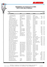
Diagram <strong>for</strong> SO 210.90.80.70.60.50.40.30.20.1008/11/1998 00:09,5008/11/1998 01:19,5008/11/1998 02:29,50Measuring period: 08-11-98 at 00,09,5009-11-98 at 00,09,5008/11/1998 03:39,5008/11/1998 04:49,5008/11/1998 05:59,5008/11/1998 07:09,5008/11/1998 08:19,5008/11/1998 09:29,5008/11/1998 10:39,5008/11/1998 11:49,5008/11/1998 12:59,5008/11/1998 14:09,5008/11/1998 15:19,5008/11/1998 16:29,5008/11/1998 17:39,5008/11/1998 18:49,5008/11/1998 19:59,5008/11/1998 21:09,5008/11/1998 22:19,5008/11/1998 23:29,501676.9 SO2rågass55.6 Ut SO246.6 Snitt kalk 3timer#I/T #I/TValues: SO 2 Raw gas (rågass): mg/Nm 3Out (Ut) SO 2 : mg/Nm 3Lime average (Snitt kalk) 3 hours: kg/hThe values placed in the box to the right of the data area represent the maximum values of thedata in question. The ordinate to the left in the data area shows the multiplication factor <strong>for</strong>calculation of the actual value.Example: Raw gas SO 2 on 08-11-98 at 00,09,50 shows the ordinate of app. 0.6, and themaximum value <strong>for</strong> raw gas SO 2 is 1676.9. Multiply the factors and you have 0.6 x 1676.9 =1006 mg/Nm 3 .The diagram situation shows that the plant is operating with a SO 2 inlet concentration of app.1200 mg/Nm 3 during the first half of the period. Then the concentration falls to 1000 mg/Nm 3 inthe latter part of the diagram. The emission requirement is