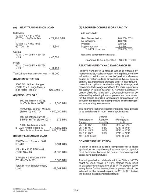
(A)HEAT TRANSMISSION LOAD(E) REQUIRED COMPRESSOR CAPACITYSidewalls:40’ x 8’ x 2 = 640 Ft 2 x60°TD x 1.9 (Table 7A)= 72,960 BTU10’ x 8’ x 2 = 160 Ft 2 x60°TD x 1.9 = 18,240Ceiling:40’ x 10’ = 400 Ft 2 x 60°TDx 1.9 = 45,600Floor:40’ x 10’ = 400 Ft 2 x 15°TDx 1.9 = 11,400Total 24 hour transmission load = 148,200(B) AIR INFILTRATION3000 Ft 3 x 9.5 air changes(Table 8) x 2 usage factor x2.11 factor (Table 9) 120,270 BTU(C) PRODUCT LOAD500 lbs. bacon x .50 sp.ht. (Table 10) x 10°TD = 2,500 BTU15,000 lbs. beer x 1.0 sp. ht.(Table 10) x 40°TD = 600,000 BTU500 lbs. lettuce x 2700BTU/24 Hr/Ton (Table 10) =675 BTU1,000 lbs. beans x 9700BTU/24 Hr/Ton (Table 10) = 4,850 BTUTotal 24 hour Product <strong>Load</strong> 608,025 BTU(D) SUPPLEMENTARY LOAD24 Hour <strong>Load</strong>:Heat Transmission148,200 BTUAir Infiltration 120,270Product 608,025Supplementary 62,544Total 24 Hour <strong>Load</strong> 939,039 BTURequired compressor capacity:Based on 16 hour operation58,690 BTU/Hr.RELATIVE HUMIDITY AND EVAPORATOR TDRelative humidity in a storage space is affected bymany variables, such as system running time, moistureinfiltration, condition <strong>and</strong> amount of product surface exposed,air motion, outside air conditions, type of systemcontrol, etc. Perishable products differ in their requirementsfor an optimum relative humidity for storage, <strong>and</strong>recommended storage conditions for various productsare shown in Tables 13 <strong>and</strong> 14. Normally satisfactorycontrol of relative humidity in a given application can beachieved by selecting the compressor <strong>and</strong> evaporatorfor the proper operating temperature difference or TDbetween the desired room temperature <strong>and</strong> the refrigerantevaporating temperature.<strong>The</strong> following general recommendations have provento be satisfactory in most normal applications:DesiredTDTemperature Relative (RefrigerantRange Humidity to Air)25°F. to 45°F. 90% 8°F. to 12°F.25°F. to 45°F. 85% 10°F. to 14°F.25°F. to 45°F. 80% 12°F. to 16°F.25°F. to 45°F. 75% 16°F. to 22°F.10°F. <strong>and</strong> below — 15°F. or less200 Watts x 12 hours x 3.41BTU/Hr1/2 H.P. x 4250 BTU/Hr-Hr(Table 16) x 242 People x 2 Hrs/Day x 840BTU/Hr (Table 17)Total 24 hour Supplementary<strong>Load</strong>8,184 BTU51,000 BTU3,360 BTU62,544 BTUCOMPRESSOR SELECTIONIn order to select a suitable compressor for a givenapplication, not only the required compressor capacitymust be known, but also the desired evaporating <strong>and</strong>condensing temperatures.Assuming a desired relative humidity of 80%, a 14° TDmight be used, which in a 40°F. storage room resultin evaporating temperature of 26°F. To provide somesafety factor for line losses, the compressor should beselected for the desired capacity at 2°F. to 3°F. belowthe desired evaporating temperature.© 1968 Emerson Climate Technologies, Inc.All rights reserved.16-2
<strong>The</strong> condensing temperature depends on the type ofcondensing medium to be used, air or water, the designambient temperature or water temperature, <strong>and</strong> thecapacity of the condenser selected. Air cooled condensersare commonly selected to operate on temperaturedifferences (TD) from 10°F. to 30°F. the lower TD normallybeing used for low temperature applications, <strong>and</strong>higher TDs for high temperature applications where thecompression ratio is less critical. For the purposes ofthis example, a design TD of 20°F. has been selected,<strong>and</strong> in 100°F. ambient temperatures, this would resultin a condensing temperature of 120°F.COMPONENT BALANCINGCommercially available components seldom will exactlymatch the design requirements of a given system, <strong>and</strong>since system design is normally based on estimatedpeak loads, the system may often have to operate atconditions other than design conditions. More thanone combination of components may meet the performancerequirements, the efficiency of the systemnormally being dependent on the point at which thesystem reaches stabilized conditions or balances underoperating conditions.<strong>The</strong> capacities of each of the three major systemcomponents, the compressor, the condenser, <strong>and</strong> theevaporator, are each variable but interrelated. <strong>The</strong>compressor capacity varies with the evaporating <strong>and</strong>condensing temperatures. For illustration purposes anair cooled condenser will be considered, <strong>and</strong> for a givencondenser with constant air flow, its capacity will varywith the temperature difference between the condensingtemperature <strong>and</strong> the ambient temperature.<strong>The</strong> factors involved in the variation in evaporator capacityare quite complex when both sensible heat transfer<strong>and</strong> condensation are involved. For component balancingpurposes, the capacity of an evaporator whereboth latent <strong>and</strong> sensible heat transfer are involved (awet coil) may be calculated as being proportional to thetotal heat content of the entering air, <strong>and</strong> this in turn isproportional to the wet bulb temperature. For wet coilconditions, evaporator capacities are normally availablefrom coil manufacturers with ratings based on the wetbulb temperature of the air entering the coil. For conditionsin which no condensation occurs (a dry coil) theevaporator capacity can be accurately estimated onthe basis of the dry bulb temperature of the air enteringthe coil.Some manufacturers of commercial <strong>and</strong> low temperaturecoils publish only ratings based on the temperaturedifference between entering dry bulb temperature <strong>and</strong>the evaporating refrigerant temperature. Although frostaccumulation involving latent heat will occur, unless thelatent load is unusually large, the dry bulb ratings maybe used without appreciable error.Because of the many variables involved, the calculationof system balance points is extremely complicated. Asimple, accurate, <strong>and</strong> convenient method of forecastingsystem performance from readily available manufacturer’scatalog data is the graphical construction ofa component balancing chart. <strong>The</strong> following exampleillustrates the use of such a chart in checking the possiblebalance points of a system when selecting equipment.To illustrate the procedure, tentative selectionsof a compressor, condenser, <strong>and</strong> evaporator have beenmade for the sample load previously calculated.Figure 69 shows the compressor capacity curves aspublished by Emerson Climate Technologies, Inc. onthe Copel<strong>and</strong>® br<strong>and</strong> compressor specification sheet.It should be noted that Copel<strong>and</strong>® br<strong>and</strong> compressorcapacity curves for Copelametic® compressors arebased on 65°F. return suction gas. In order to realize thefull compressor capacity, the suction gas must be raisedto this temperature in a heat exchanger. If the suctiongas returns to the compressor at a lower temperature,or if the increase in suction gas temperature occurs dueto heat transfer into the suction line outside the refrigeratedspace, the effective compressor capacity will besomewhat lower. In the example, the desired capacitywas 58,690 BTU/hr. at 24°F. evaporating temperature<strong>and</strong> 120°F.condensing temperature, <strong>and</strong> this compressorwas the closest choice available, having a capacityof 57,000 BTU/hr. at the design conditions.Figure 70 shows the same compressor curves, withthe condenser capacity curves for the tentative condenserselection superimposed. From the condensermanufacturer’s data, condenser capacity in terms ofcompressor capacity at varying evaporating temperaturesare plotted, <strong>and</strong> the condenser capacity curves canthen be drawn. Note that the net condensing capacitydecreases at lower evaporating temperatures due tothe increased heat of compression.It is now possible to construct balance lines for the compressor<strong>and</strong> condenser at various ambient temperaturesas shown in Figure 71. For an ambient temperatureof 100°F., point A would represent the balance pointif the compressor were operating at a suction pressureequivalent to a 28°F. evaporating temperature<strong>and</strong> 120°F. condensing temperature. At this point thecapacity of the condenser would exactly match that ofthe compressor at a 20° TD (condensing temperatureminus ambient temperature). <strong>The</strong> balance point is determinedby the intersection of the 20°F. TD condensercapacity curve with the compressor capacity curve for(continued on p. 16-9)16-3© 1968 Emerson Climate Technologies, Inc.All rights reserved.