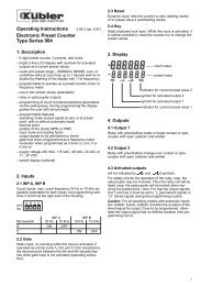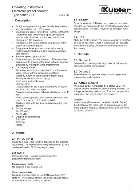
Operating instructions Electronic preset counter Type series 717
Operating instructions Electronic preset counter Type series 717
Operating instructions Electronic preset counter Type series 717

You also want an ePaper? Increase the reach of your titles
YUMPU automatically turns print PDFs into web optimized ePapers that Google loves.
5.2.10 Shape of output 1 (only if <strong>preset</strong> 1 is activated)5.2.14 End of programmingPermanent signal of output 1, activatedat count value ≥ <strong>preset</strong> 1 in adding modeand at count value ≤ <strong>preset</strong> 1 insubtracting modePermanent signal of output 1, willbecome passive at count value ≥ <strong>preset</strong> 1in adding mode and at count value ≤<strong>preset</strong> 1 in subtracting modeProgramming is carried out once more.The values input can be checked andmodified.Programming is complete and the valuesinput are taken over as new parameters.Then the device is ready for operation.Timed signal of output 1 will becomepassive at count value ≥ <strong>preset</strong> 1 inadding mode and at count value ≤ <strong>preset</strong> 1in subtracting modeTimed signal of output 1 is activated atcount value ≥ <strong>preset</strong> 1 in adding modeand at count value ≤ <strong>preset</strong> 1 insubtracting mode5.3 Speed indicator / frequency meter modesettingIn the speed indicator / frequency meter mode, inputsINP B, RESET and GATE have no function.5.2.11 Duration of the timed signal of output 1 (only ifa timed signal has been programmed in 5.2.10)5.3.1 Polarity of the inputs- Subject to change without prior notice -5.2.12 Shape of output signal 2The duration can be set between 0.01 sec.and 99.99 sec.A 0.00 setting is not acceptedPermanent signal of output 2, activatedat count value ≥ <strong>preset</strong> 2 in adding modeand at count value ≤ 0 in subtracting modenpn: switching to 0 Vpnp: switching to +24 V5.3.2 Activation of the 30 Hz filtermax. counting frequency: 20 kHzmax. counting frequency: 30 HzPermanent signal of output 2, willbecome passive at count value ≥ <strong>preset</strong> 2in adding mode and at count value ≤ 0 insubtracting modeTimed signal of output 2 will becomepassive at count value ≥ <strong>preset</strong> 2 inadding mode and at count value ≤ 0 insubtracting modeTimed signal of output 2 is activated atcount value ≥ <strong>preset</strong> 2 in adding modeand at count value ≤ 0 in subtracting mode5.3.3 Setting of the scale factorScale factor setting range from 00.0001 to99.9999. Fixed decimal point set to 4decimal places.A ”0” setting is not accepted.5.2.13 Duration of the timed signal of output 2 (only ifa timed signal has been programmed in 5.2.12)The duration can be set between 0.01 sec.and 99.99 sec.A 0.00 setting is not accepted5.3.4 Decimal point settingThe decimal point determines the number ofdecimal places displayed. It is only used fordisplaying purposes and has no influence onthe counting.0 no decimal place0.0 one decimal place0.00 two decimal places0.000 three decimal places5
5.3.5 Display mode5.3.10 Shape of output signal 2Conversion and display of the frequency /speed in 1/sec.Conversion and display of the frequency /speed in 1/min.Permanent signal. Is activated at countvalue ≥ <strong>preset</strong> 2.Permanent signal. Will become passiveat count value ≥ <strong>preset</strong> 2.Timed signal. Will become passive atcount value ≥ <strong>preset</strong> 2.5.3.6 Maximum pulse waiting timeThis value indicates the time during which the device will wait for apulse before displaying a 0 speed.Timed signal. Is activated at count value≥ <strong>preset</strong> 2.Maximum delay 01.1 sec. (minimumvalue)Maximum delay 99.9 sec.Values below 1.1 sec. are ignored and set automatically to 1.1 sec.5.3.11 Duration of the timed signal of output 2 (only ifa transient signal has been programmed in 5.3.10)The duration can be set between 0,01 sec.and 99,99 sec.A 0.00 setting is not accepted5.3.7 Preset 15.3.12 End of programmingPreset 1 activatedPreset 1 disactivated and without functionProgramming is carried out once more.The values input can be checked andmodified.Programming is complete and the valuesinput are taken over as new parameters.Then the device is ready for operation.5.3.8 Shape of output 1 (only if <strong>preset</strong> 1 is activated)6Permanent signal. Is activated at countvalue ≥ <strong>preset</strong> 1.Permanent signal. Will become passiveat count value ≥ <strong>preset</strong> 1.Timed signal. Will become passive atcount value ≥ <strong>preset</strong> 1.Timed signal. Is activated at count value≥ <strong>preset</strong> 1.5.3.9 Duration of the timed signal of output 1 (only if atimed signal has been programmed in 5.3.8)The duration can be set between 0.01 sec.and 99.99 sec.A 0.00 setting is not accepted6. Setting of the <strong>preset</strong>sIf a push-button with an arrow or the ”P” push-button ispressed, the device jumps from the display of the<strong>counter</strong> to the display of the <strong>preset</strong> 1. A secondoperation of push-button ”P” switches to the <strong>preset</strong> 2.About 4 seconds after the last operation of a pushbuttonthe device jumps back to the display of the<strong>counter</strong> and takes over a new <strong>preset</strong> value.Exception: in the time <strong>counter</strong> mode, the new value istaken over immediately.Once the <strong>preset</strong> is displayed, the “” push-buttonallows to choose the decade to be modified. Thisdecade then blinks at a 1 Hz frequency. The “” pushbuttonallows you to raise the value of the decade. Onthe most significant decade, after the value ”9”, thesign ”-” is displayed. The following operation of the “”push-button displays ”-1” again. A new operation of the“” push-button lets the display of this decade startagain at ”0”.Caution: in case of automatic repetition, <strong>preset</strong> 2cannot be given negative values.
7. Connections8. Technical characteristicsSupply voltage:Display:90..250 VAC, 5VA max. or10..30 VDC, 1W max.6 digits, red 7-segmentLED’s, display height 8 mmOnly with the optionalserial interfacePolarity of the input signals:programmable in common forall inputs (npn or pnp).Input resistance: approximately. 10 kW7.1 Terminal assignment X1Supply voltage and outputsTerminal No AC versions 10..30 VDC versions1 Output 1 – Relay contactCollector when optocoupler output2 Output 1 – Relay contactEmitter when optocoupler output3 Output 2Common relay contact (C)Emitter when optocoupler output4 Output 2 RelayClosing contact (NO)5 Output 2 Relay with opening contact (NC)Collector when optocoupler output6 Supply voltage 10..30 VDC90..250 VAC <strong>Operating</strong> voltage7 Supply voltage 0 VDC (GND)90..250 VACAttention: In case of a and a setting(reversed relay control), the connections of terminals 4and 5 are reversed:Terminal No AC and DC versions4 Opening contact relay (NC)5 Closing contact relay ( NO)7.2 Terminal assignment X2InputsTerminal Designation AC versions 10..30 VDCNo.versions1 +24 VDC Sensor supply Not connectedvoltage2 0 VDC Reference voltageNot connected(GND)3 INP A Counting input A4 INP B Counting input B5 RESET Reset input6 GATE GATE input7 KEY Push-button locking inputCounting frequency:20 kHz (10 kHz with phasediscriminator), can be reduced to30 Hz. In case of automaticrepetition, 1.2 kHz without loss ofpulses (700 Hz with phasediscriminator and pulse multiplicationby 2).Minimum pulse duration for control inputs:5 msInput switching level:With AC supply voltage:log.”0”: 0..4 VDClog.”1”:12..30 VDCPulse shape:With DC supply voltage:log.”0”: 0..0,2 x U Blog.”1”: 0,6 x U B..30 V DCany shape (Schmitt trigger inputs)Accuracy in the frequency meter/speed indicator mode:< 0,1 %Accuracy in the time <strong>counter</strong> / operating time <strong>counter</strong>mode:± 50 ppmOutput 1:Output 2:Relay with potential-freemake or break contact,programmable as opening or closingcontact.Switching voltage max. 250 VAC /125 VDC. Switching current max. 3ASwitching current min. 30 mA DCSwitching power 90 W /750 VAor npn optocoupler with opencollector and emitterSwitching power: 30 VDC /15 mAU CESATfor l C= 15 mA: max. 2.0 VDCU CESATfor l C= 5 mA: max. 0.4 VDCRelay with potential-free change-overcontact, programmable asopening or closing contact.Switching voltage max. 250 VAC /300 VDC.Switching current max. 3ASwitching current min. 30 mA DCSwitching power 50 W / 2000 VA7
or npn optocoupler with opencollector and emitterSwitching power: 30 VDC / 15 mAU CESATfor l C= 15 mA: max. 2.0 VDCU CESATfor l C= 5 mA: max. 0.4 VDCOutputs response time:Relay: approx. 7 msOptocoupler: approx. 2 msData storage:at least 10 years or 10 6 recordingcycles (switching on and off thedevice)Sensor supply voltage:+24 VDC ± 15 % / 100 mAwith AC power supplyFuses:recommended external fuses:for DC: 0.125 A time-delay fusefor AC: 0.1 A time-delay fuseInterference immunity:EN 55011 class B and EN 50082-2with shielded control cables.<strong>Operating</strong> temperature:-10°C.. +50°CStorage temperature:-25°C..+70°CWeight:approx. 200 g (AC version with relay)9. Delivery specification• Counter <strong>717</strong>• Screw terminal (7 poles) pitch 5,08 mm.• Screw terminal (7 poles) pitch 3,81 mm.• Frame for screw mounting, opening 50 x 50 mm• Frame for clamp mounting, opening 50 x 50 mm• Clamp• With the serial interface option: screw terminal (5poles) Pitch 3,81 mm.10. Order code6.<strong>717</strong>.01X.XXX11. DimensionsOption00 = none05 = RS232 serial interface06 = RS422 serial interface07 = RS485 serial interfaceSupply voltage0 = 90..250 VAC3 = 10..30 VDCOutputs0 = relay1 = optocouplerProtection:Housing colour:Cleaning:IP 65 (front side)dark greyThe front side of the device must becleaned only with a damp soft cloth.Fritz Kübler GmbH • Zähl- und Sensortechnik • P.O.BOX 3440 • D-78023 VS-SchwenningenGERMANY • Tel. +49 77 20 / 39 03-0 • FAX +49 77 20 / 2 15 64 • E-Mail:sales@kuebler-gmbh.de