Lifetime Predictions of Bend Optimized GGP Single Mode Fiber for ...
Lifetime Predictions of Bend Optimized GGP Single Mode Fiber for ...
Lifetime Predictions of Bend Optimized GGP Single Mode Fiber for ...

Create successful ePaper yourself
Turn your PDF publications into a flip-book with our unique Google optimized e-Paper software.
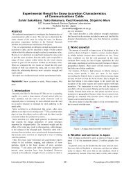
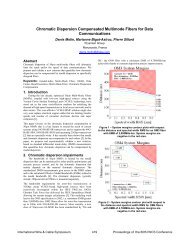
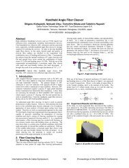
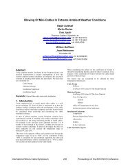
<strong>Lifetime</strong> <strong>Predictions</strong> <strong>of</strong> <strong>Bend</strong> <strong>Optimized</strong> <strong>GGP</strong> <strong>Single</strong> <strong>Mode</strong> <strong>Fiber</strong> <strong>for</strong> FTTHRequirementsHen-Tai Shang, Li-Shing Hou, Gary Chou, Ray HsiehPrime Optical <strong>Fiber</strong> CorporationScience Park, Chu-Nan 350 Taiwan Roc+886-37-586999 hentai@p<strong>of</strong>c.com.twAbstract<strong>Fiber</strong> To The Home (FTTH) demand bend optimized fiber, however,most commercially available bend enhanced fiber only addressesthe optical per<strong>for</strong>mance at tight bends, it does not improve themechanical property <strong>of</strong> the fiber. This paper describes designs <strong>of</strong> the<strong>GGP</strong> single mode fiber which improves the fiber mechanicalproperty independently to its optical per<strong>for</strong>mance. Combining the<strong>GGP</strong> fiber design with low bending loss per<strong>for</strong>ms, bend optimizedsingle mode fibers were developed. Their dynamic fatigueparameter nd were found to be greater than 30. With thatin<strong>for</strong>mation, we can estimate their lifetime.Keywords: <strong>GGP</strong>; fiber; FTTH; mechanical failure; lifetime;fatigue parameter; bend; MDU.1. Introduction<strong>GGP</strong> fiber first developed by 3M Company and presented in thisconference in 1995 [1] The term <strong>GGP</strong> has been designated as ageneric descriptor <strong>of</strong> this fiber design with specific reference to theGlass core/Glass clad/Permanent polymetric coating and withadditional two layer <strong>of</strong> Acrylate coating construction (see Figure 1).network structure simulation model the allowed fiber storage lengthand bending radius R <strong>of</strong> storage depend critically on the fatigueparameter n. In this paper we will show by applying a 5 um thick P-coating to a normal ITU-T G.657 fiber, a new class <strong>of</strong> <strong>GGP</strong> singlemode fiber which has both good optical per<strong>for</strong>mance and superiormechanical property was created. Its aging properties, fatigueparameter n, and lifetime predictions were studied.2. <strong>GGP</strong> <strong>Single</strong> <strong>Mode</strong> <strong>Fiber</strong> Design<strong>GGP</strong>(115/125/250) designate fiber with glass clad = 115 um, P-coatOD = 125 um and Acrylate coating to 250 um. “<strong>GGP</strong>R15” fiber isa low bending loss fiber (G657A) with the above construction.<strong>GGP</strong>(125/135/250) designate fiber with glass clad = 125 um, P-coatOD = 135 um and Acrylate coating to 250 um. “<strong>GGP</strong>R15X” fiber isa low bending loss fiber (G657A) with the above construction.3. <strong>Fiber</strong> Static Fatigue Aging TestThe static fatigue aging test schematic is show in Figure 2. To testany fiber, batches <strong>of</strong> twenty short fiber pieces were loaded intotest Face Plate. The Face Plate distance is adjusted so the glassfiber bending gap (d1) is equal to 3.5 mm. Loaded Face Plate wasimmerged in 90 degree Celsius hot water, and an acoustic sensoris used to monitor the fiber breakage and automatically recordedbreakage times. Failure probability verses breakage times wererecorded and results were shown in Figure 3.Four Classes <strong>of</strong> fiber were tested: Commercial legacy fiber frommany different sources designated as STD(125/250), the original<strong>GGP</strong> multimode fiber designated as <strong>GGP</strong>(100/125/250) alongwith the two new classes <strong>of</strong> fiber <strong>GGP</strong>(115/125/250) and<strong>GGP</strong>(125/135/250).Figure 1. Cross section <strong>of</strong> <strong>GGP</strong> fiber constructionThe original design was directed towards multimode optical fiber<strong>for</strong> use in data communication application. Later <strong>GGP</strong> multimodefiber with 12.5 um thickness P-coating was used in ferrule-lessinterconnect applications [2], <strong>GGP</strong> fiber comprises this patented P-coating resists strength degradation upon exposure to hightemperature and high humidity environments. It provide muchimproved mechanical protection to the fiber glass cladding, so <strong>GGP</strong>fiber do have much longer lifetime expectation than legacy fiber.Recently ITU-T Rec. G.657 specified a class <strong>of</strong> bending lossinsensitive single mode fiber, and its more stringent lifetimerequirements is discussed in its Appendix 1; <strong>for</strong> a simplifiedFigure 2 Static Fatigue Aging Test setupInternational Wire & Cable Symposium 266 Proceedings <strong>of</strong> the 57th IWCS
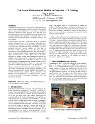
<strong>GGP</strong>(115/125/250)<strong>GGP</strong>(125/135/250)<strong>GGP</strong>(100/125/250)Dynamic fatigue data2008/7/24Date : Platen Velocity = 1000um/s,100um/s,10um/s,1um/s X-Bar = -0.259POFC <strong>GGP</strong>R15 G008Z7B15F1DY<strong>Fiber</strong> ID : Sample Size <strong>for</strong> each platen velocity = 16 Y-Bar = 0.787Cladding : Temperature = 23 +/- 1 C Nd = 34.51OD 114.7 umCoating OD : 246.8 um Humidity = 46 +/- 2 % Ndu = 36.34Operator : 370Pre-Conditioning time Ndl = 32.87= 18 HrsFailure Probability (%)Log (fracture stress) GPa0.90.850.80.750.7<strong>GGP</strong>R15y = 0.0298x + 0.7943R 2 = 0.9588Nd = 1/0.0298+1 = 34.50.65STD(125/250)Time to break (sec)•Static Fatigue <strong>Bend</strong>ing Gap d1= 3.5mm ; Immerse @90℃ DI Water.Figure 3. Static fatigue aging test resultsThe results show Legacy fibers all have median Failure Time lessthan 5 minutes, where <strong>GGP</strong> fibers all have much longer (100 to10,000 times longer) median Failure Time.4 <strong>Fiber</strong> Dynamic Fatigue MeasurementWe followed IEC-60793-1-33 Annex B set up the dynamicfatigue two-point bending method as shown in Figure 4. Thewhole movable sample holder is inside a temperature andhumidity controlled box. The test set is shown in Figure 5. Alltests were conducted in the same controlled temperature andhumidity range. Test samples were also pre-conditioned <strong>for</strong> atleast 12 hours as required. A test report sample was shown inFigure 6, and typical measured results (nd) were summarized inTable 1.0.6-2 -1.5 -1 -0.5 0 0.5 1 1.5log (V/r)Figure 6. Test report on one sample <strong>of</strong> <strong>GGP</strong>R15 fiberTable 1. Summary <strong>of</strong> Dynamic Fatigue Parameter ndCommercial fibers <strong>of</strong> company C and company F show theirfiber’s nd around 19 and our <strong>GGP</strong> fibers all show nd around 34.5 <strong>Lifetime</strong> predictionBased on experimental lifetime data on fiber wrap over 3 mmdiameter rod and the relative lifetime data <strong>of</strong> different fiber class,we have extrapolated their expected lifetime based on Power LawTheory [IEC TR 62048] as shown in figure 7.Figure 4. Schematic <strong>of</strong> two point bending methodFigure 5. Dynamic Fatigue Two Point <strong>Bend</strong>ing Test setupFigure 7. Extrapolated life time based on power lawtheory and lifetime dataOur lifetime prediction uses n = 18 <strong>for</strong> legacy fiber, and n=30 <strong>for</strong> alltype <strong>of</strong> <strong>GGP</strong> fibers. The lifetime calculated is <strong>for</strong> a simplifiednetwork structure simulation model with each individual one meterfiber wrap over <strong>of</strong> different diameter frame inside cassette and thefailure rate = 0.001% [3]. The results show the minimum frameInternational Wire & Cable Symposium 267 Proceedings <strong>of</strong> the 57th IWCS
diameter could be as small as 8 mm <strong>for</strong> all <strong>GGP</strong> fiber networks tosurvive 20 years, where legacy fiber networks could reach greaterthan 5 % failure rate in less than an hour.6 <strong>Bend</strong>ing Loss<strong>GGP</strong>R15 and <strong>GGP</strong>R7 fiber, in compliance with ITU-T G.657A andITU-T G.657B respectively, were developed and their bending lossis shown in Figure 8.10 Authors BiographyHen-Tai Shang, received his BS degree fromNCU in Taiwan in 1972. After militaryservice, he went to the US <strong>for</strong> his graduatestudies. He received his PhD degree from U.<strong>of</strong> Illinois at Urbana-Champaign and joinedAT&T Bell Laboratories in 1979. After 11years <strong>of</strong> R/D work at Bell Labs, he went backto Taiwan in 1990 and a year later foundedPrime Optical <strong>Fiber</strong> Corporation; now he isthe company Chief Technology Officer. He has engaged indevelopment work <strong>of</strong> many different optical fibers <strong>for</strong>communications, fiber sensors, and fiber lasers. Currently he isalso serving as VP <strong>of</strong> Taiwan Optical Communication IndustryAlliance (TOCIA).Li-Shing Hou received his PhD degree inPhysics from National Tsing-Hua Universityin 1999 and then he joined Academica Sinicawhere he worked <strong>for</strong> CERN LHC project todevelop mini optical devices. In 2007 hejoined Prime Optical <strong>Fiber</strong> Corporationwhere his main task is on fiber applicationand product management.Figure 8. <strong>Bend</strong>ing Loss at 1550 nm7 ConclusionsWe have developed a new class <strong>of</strong> <strong>GGP</strong> single mode fiber. Thesefibers feature low bending loss and long lifetime - A class <strong>of</strong> trulybend optimized fiber. This new class <strong>GGP</strong> fiber can be fusionsplicedto legacy fiber by using ordinary fusion splice machines. Itis also suitable to use with commercial available mechanical splicesand field assembly connectors. Using these fibers, a very simple 3mm OD cable can be made with one or two 250 um <strong>GGP</strong> fibersinside. Such cable will be ideal <strong>for</strong> FTTH and MDU deployment.8 AcknowledgmentsSpecial thanks to 3M Company <strong>for</strong> their assistance to thedevelopment <strong>of</strong> this work.9 References[1] J. C. Novack, F. Bacon, B. J. Cronk, J. W. Laumer, J. M.Moser and B. A. Rabine, “Optical <strong>Fiber</strong> Design For ImprovedMechanical Properties,” p. 162 International Wire & CableSymposium Proceedings 1995.[2] T. P. Berger, J. W. Laumer, C. B. Walker Jr. and J. C. Novack,“<strong>Fiber</strong> Per<strong>for</strong>mance in Ferrule-Less Interconnects,” p. 560International Wire & Cable Symposium Proceedings 1999.[3] ITU-T Rec. G.657 (12/2006) Appendix 1.Gary Chou, received his master degree fromNCU in Taiwan in 1995. After militaryservice, he joined Prime Optical <strong>Fiber</strong>Corporation in 1997 where he worked onmany different optical fibers <strong>for</strong>communications, fiber sensors, and fiberlasers, currently as R&D manager.Ray Hsieh received his master degree inPhysical Chemistry from National Tsing-HuaUniversity in 2000. In 2001 he joined thePrime Optical <strong>Fiber</strong> Corporation, where heworked in the R&D group, and now is atechnical support engineer.International Wire & Cable Symposium 268 Proceedings <strong>of</strong> the 57th IWCS