Two-Diver Communications Manual - DECA | Diving Equipment ...
Two-Diver Communications Manual - DECA | Diving Equipment ...
Two-Diver Communications Manual - DECA | Diving Equipment ...

You also want an ePaper? Increase the reach of your titles
YUMPU automatically turns print PDFs into web optimized ePapers that Google loves.
<strong>Two</strong>-<strong>Diver</strong> Air IntercomPart #: 100-400Kirby Morgan Dive Systems, Inc.1430 Jason WaySanta Maria, CA 93455, USATelephone (805) 928-7772FAX (805) 928-0342E-Mail: Info@KirbyMorgan.comWeb Site: www.KirbyMorgan.comPublication Date of this Document: December 4, 2008SuperLite-17, SuperLite-27, SuperLite-17C, SuperLite-17K, SuperFlow 350,Band Mask, Kirby Morgan, DCS-2A, EXO-26 and KMB are all registered trademarksof Kirby Morgan Dive Systems, Inc. Use of these terms to describe productsthat are not manufactured by KMDSI is not permitted.© Copyright 1987-2009 Kirby Morgan Dive Systems, Inc. All rights reserved.This manual is made available for the express use of owner of this Kirby Morganproduct. No part of this manual may be reproduced, stored in any retrieval system,or transmitted, or used in any form or by any means, whether graphic, electronic,mechanical, photocopy, or otherwise by technology known or unknown, withoutthe prior written permission of Kirby Morgan Dive Systems, Inc.Document # 081204001
Controls And ConnectionsSection 4Controls And Connections:Before using the KMDSI <strong>Diver</strong> Communication System, you should familiarizeyourself with its operating controls and connections. Improper use of controlsand connections will deprive the user of the full benefits of this communicationsystem.Tender ControlsPower Switch–Applies power to the unit from internal batteries or fromexternal source.Speaker Switch–Turns panel speaker and microphone on/off. It may benecessary to turn speaker off when using a headset to prevent feedback.Push To Talk All <strong>Diver</strong>s Switch–This Switch allows tender to both diverscommunication in 2 and 4-wire mode. (No push to talk is required when operatingin 4-wire mode, when using an optional head set and boom microphone).In 4-Wire mode, this switch allows the tender to interrupt divers with a prioritymessage; all divers will be listening.<strong>Diver</strong> 1 & <strong>Diver</strong> 2 Push To Talk (2 Wire Mode)–These switches allowthe tender to talk to each diver, individually. In the 4 wire mode either of theseswitches will work the same as the “Push to talk all divers” switch.Earphone Volume–Controls panel speaker and/or tender headset volume.Use as master volume control, clockwise increases volume.Battery Condition Indicator–Steady GREEN light indicates battery voltagelevel is good. Blinking GREEN light indicates battery voltage is approachinga low level. Steady RED light indicates battery voltage is below the levelnecessary to guarantee proper operation.B CAUTIONWhen Battery Condition indicator is steady RED light, communicationwill stop.8 © Copyright 1970-2008 Kirby Morgan Dive Systems, Inc. All rights reserved. Document # 081204001
Controls And ConnectionsPanel Speaker–5 inch round speaker, operates when Speaker Switch is ON.Tender Connections:Headset Jack (output/input)–Is a dual banana jack (color coded black)connection for headset earphones or external remote speaker. It functions as anearphone (output) and a microphone (input) when PTT switches depressed. In2-wire mode of operation both headset microphone and earphones are pluggedinto this jack, conversation (up-link & down-link) are switched automaticallywhen push to talk switch is actuated. In Simulcom mode this jack is earphoneonly, both up-link & downlink conversations are heard.Microphone Jack (input)–Is a dual banana jack (color coded red) connectionfor the headset microphone. Tender microphone volume control adjusts thesensitivity of the input.Push To Talk Jack–Is a dual banana jack (color coded yellow) connectionfor remote keying of push to talk.<strong>Diver</strong> Controls:Microphone Volume–Controls amplification of diver’s microphone signal,therefore control diver’s volume to tender and to all divers. Each diver circuit hasits own volume control.Earphone Volume–Controls diver’s earphone signal, therefore controldiver’s hearing volume from tender and to all divers. Each diver circuit has itsown volume control.Push To Talk–Momentary switch which allows the specific diver to heartender and all divers (diver switches to listening mode) as long as switch isdepressed, used in the two-wire mode.<strong>Diver</strong> Connections:In the 2 wire mode of operation, both diver microphone and earphone bananaplugs are stacked into the umbilical microphone jack (red binding posts). Conversation’s(up-link & down-link) are switched automatically when push to talkswitch is actuated.© Copyright 1970-2008 Kirby Morgan Dive Systems, Inc. All rights reserved. Document # 081204001 9
Controls And ConnectionsIn the 4-wire mode, only the diver microphone banana plug is connected into theumbilical microphone jack.Earphone Jack (output)–4 Wire - This connector is dual 5-Way BindingPost Jack (color coded black). It is the connection point for the diver’s earphonewhen operating in the 4-wire mode.Other Connections:External Battery - (Input)–External 12 VDC non-regulated power input,to operate the unit from an external power source. Power requirements are notless than 11 or more than 22 volts. The External Battery Input Jacks are used forcharging the internal battery.B WARNINGWhen using an external power source, it is required to use aninsulated DC power supply that has very low ripple voltage. Ithas to be properly insulated from AC line for diver protectionand safety. An improperly insulated power supply could causediver electric shock. This could lead to serious personal injuryor death.Tape Recorder–provides an isolated output, of both diver and tender conversations(balanced), suitable to drive a tape recorder or audio input of a VCR.This feature allows recording of conversations between diver and tender.10 © Copyright 1970-2008 Kirby Morgan Dive Systems, Inc. All rights reserved. Document # 081204001
Problems And Their Possible Causes<strong>Diver</strong> 2 Up-link Check17. Move headset microphone into Microphone (input) <strong>Diver</strong> 2.18. Talk into headset. You should hear yourself in the headphones with plenty ofvolume.This verifies <strong>Diver</strong> 2 Microphone (input).Problems And Their Possible CausesUnit Not OperatingCheck to see that unit is turned on, (speaker and headset switch). Check that batterycondition indicator is steady green (ok). Check to see that connections areproper, correct if necessary. Use diver radio field check procedure to determineif problem is within the unit or elsewhere within the communication system.Check to see that the P.C. Card connectors are properly seated, there should beno gap between the bottom of the connector housing and the connector headeron the circuit card. Check that connectors are installed correctly, (headers are notoffset left or right). Push connector down and recheck.A great number of problems are very simple failures and can often be found bya very careful and close inspection of the unit or system. Logical deductions andequipment familiarity can often reduce the suspected area to just one componentor circuit. Often upon examination, clues are revealed which can also aid inlocating and correcting the problem. Visual inspections should include checkingall screws for tightness, all solder joints for correctness, broken parts, corrosion,electrolysis, foreign material, check connectors for proper insertion and alignment.Check to see that unit is turned on, speaker on.Check that battery condition is ok, (battery condition indicator). Operate fromline voltage or charge batteries, depending upon options.Check to see that connections are proper, correct if necessary.Check operating voltage, using a digital voltmeter or equivalent, measure thevoltage across the yellow push to talk jacks on the front panel. The voltage mustbe greater than 9.5 volts D.C. for the unit to operate reliably.Low VolumeCheck volume control settings, adjust if desired. Check diver connections, correctif bad. Use diver radio field check procedure. Check for low batteries.© Copyright 1970-2008 Kirby Morgan Dive Systems, Inc. All rights reserved. Document # 081204001 13
Problems And Their Possible CausesGarbled Voice to <strong>Diver</strong>Tender volume to diver is set too high – reduce diver earphone volume. <strong>Diver</strong>searphones corroded or defective, replace same. Tender’s microphone (speaker)defective or full of moisture, empty water out of speaker or replace tender headset.Check diver communication cable and connections.Garbled Voice to TenderThe diver volume to tender is set too high; reduce tender volume. Tender’s headsetis marginal, speaker has water in it, or diver’s microphone is marginal, damagedcommunication cable or connections. Substitute with known good units todetermine exact problem and correct.<strong>Diver</strong> Cuts OutCheck for intermittent connection, substitute system components with knowngood units to determine exact problem and correct fault.Connections:Most diver communications problems are caused by bad connections. The timespent in making good connections will result in years of good communications.All connections must be soldered to last for any period of time. Copper wiremust be tinned as a minimum, it is strongly suggested thatdual banana plugs be used for topside connections. This provides a convenientand secure connection which will last for several years if treated with a reasonableamount of care.All cable splices must be soldered, splices should be staggered, covered withshrink tubing preferably shrink tubing with an adhesive sealant, and a generalsplice cover to protect the connections. Potting of splices is a very good andprofessional approach, however not necessary to create a reliable splice.Push To Talk Does Not Function But Tender Hears <strong>Diver</strong>(2-Wire Mode)Find which push to talk switch is not working (PTT All <strong>Diver</strong>s, PTT-<strong>Diver</strong> 1 &PTT-<strong>Diver</strong> 2). Check connection to tender headset microphone if used. Checkbattery condition indicator to be steady green. It could be a broken wire on theswitch terminals or a bad connection with PC card.<strong>Diver</strong> Hears Tender But Tender Cannot Hear <strong>Diver</strong>, OrVolume Is Very LowCheck to see if diver is connected to microphone and not earphone. Check to seethat volume levels are not turned down. Inspect diver connections, hat components.14 © Copyright 1970-2008 Kirby Morgan Dive Systems, Inc. All rights reserved. Document # 081204001
Problems And Their Possible CausesFeedback in 4-Wire ModeCheck orientation of cable wiring, earphone and microphone wire pairs shouldbe opposing wires.These situations may cause feedback, tender’s speaker on while headset is connected,unused diver communications connected to system, damaged communicationscable or connections, (open or shorted wires or connections). Resistancefor a new cable should be in excess of 10 Meg ohms.In a situation where the communication cable is damaged, reduce volume todiver as low as possible (reduce side-tone), or go to 2-wire operation until cablecan be repaired.Feedback can be caused by leakage between the microphone and earphone wiresin the umbilical better know as a cross coupling signal between umbilical wires.Adjust the diver volume to determine which umbilical has cross coupling signalbetween wires. Rotate the earphone banana plug (black) 180 degrees on thecommunicator as this it may stop the feedback.DistortionThis can be caused by several conditions – Volumes is adjusted too high, systemis on the verge of feedback, marginal components (earphones or microphone).Check by substitution, replace defective component. Note: when operatingwith a standby diver who does not have his hat/helmet on, acoustic feedback ordistortion may occur. Correct by turning his volume down or disconnecting hiscommunication cable (at least his microphone, which will reduce overall systemnoise).B CAUTIONShould it become necessary to replace the 12V battery, be sureto connect the RED wire to the Positive terminal and the BLACKwire to the Negative terminal? There is a fuse F1 in the amplifiercard. When reversing internal battery terminals, this fusewill blow to protect the electronic circuits and wiring from beingdamaged. F1 fuse is replaceable with 3.15A-250V Slow BlowMicro Fuse.Low Battery IndicationIf battery voltage is low, then charge battery for a minimum of 24 hours. Batterywill charge anytime the unit is plugged by external DC power supply. The© Copyright 1970-2008 Kirby Morgan Dive Systems, Inc. All rights reserved. Document # 081204001 15
Problems And Their Possible Causespreferred method to charge the battery is with power off. The charger circuitis designed to maintain the battery at full charge during normal operation, andpower can be left on without damage to the battery.The battery voltage can be checked by measuring across the yellow jacks on thefront panel. Turn the unit on and disconnect external DC power supply.The voltage at full charge with the external DC power is on should be between13.4 and 14.5 volts. With the external DC power is off, a fully charged batteryshould be between 11.75 and 12.75 volts. The battery voltage of a dischargedbattery is 10.0 volts; the battery should not be operated below this point as permanentdamage will occur.16 © Copyright 1970-2008 Kirby Morgan Dive Systems, Inc. All rights reserved. Document # 081204001
Figure 22-Wire Mode© Copyright 1970-2008 Kirby Morgan Dive Systems, Inc. All rights reserved. Document # 081204001 17
Figure 34-Wire Mode18 © Copyright 1970-2008 Kirby Morgan Dive Systems, Inc. All rights reserved. Document # 081204001
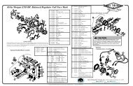
Figure 4Blowaparts/Parts List415-105A CommunicatorRef. Qty. Part No. Descriptionn/a 1 415-105A-200 PC CARD ASSEMBLY, MODEL 415-105An/a 1 415-105A-400 FRONT PANEL ASSEMBLY, MODEL 415-105A415-105A-400 Front Panel Assembly Parts ListRef. Qty. Part No. Description1 1 415-105A-001 Front Panel, DSI Communicator2 3 P16NP-10K Potentiometer, 10K ohm with Knob3 3 PBSWITCH Switch, Push Button, Sealed, N.O.4 2 7580K6 Switch, Toggle, SPST5 2 1498-102 Jack, Banana, Red6 2 1498-103 Jack, Banana, Black7 2 1498-107 Jack, Banana, Yellow8 2 5168 Seal, Half Boot Toggle, Grey9 1 ME161-2003 Jack, Phono with Nylon Washers, Nickel/Black10 4 14002B 5-Way Binding Post, Black11 4 14002R 5-Way Binding Post, Red12 1 579-80214 Clip, Panel Mount LED13 1 LT2462-24-D51 LED, Bi-Color Red/Green14 4 8-32X1/2HSBHC Screw, 8-32 X 1/2 Button Head S/S15 4 8NUTSSL Nut, Locking, 8-32 S/S with Nylon16 1 2143-0 Jack, Banana, Red/Black, External Battery© Copyright 1970-2008 Kirby Morgan Dive Systems, Inc. All rights reserved. Document # 081204001 19