INSTALLATION INSTRUCTIONS FOR DYNAMIC CURTAIN ... - Ventex
INSTALLATION INSTRUCTIONS FOR DYNAMIC CURTAIN ... - Ventex
INSTALLATION INSTRUCTIONS FOR DYNAMIC CURTAIN ... - Ventex

Create successful ePaper yourself
Turn your PDF publications into a flip-book with our unique Google optimized e-Paper software.
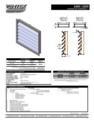
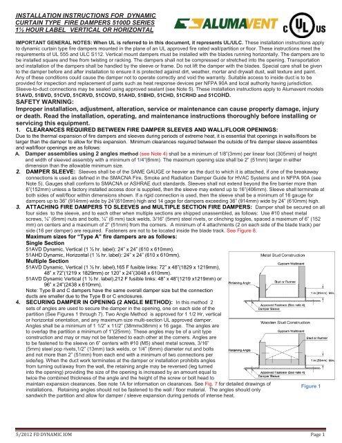
<strong>INSTALLATION</strong> <strong>INSTRUCTIONS</strong> <strong>FOR</strong> <strong>DYNAMIC</strong><strong>CURTAIN</strong> TYPE FIRE DAMPERS 5100D SERIES1½ HOUR LABEL VERTICAL OR HORIZONTALIMPORTANT GENERAL NOTES: When UL is referred to in this document, it represents UL/ULC. These installation instructions applyto dynamic curtain type fire dampers mounted in the plane of an UL approved fire rated wall/partition or floor. These instructions meet therequirements of UL 555 and ULC S112. Vertical mount dampers must be installed with the blades running horizontally. The dampers are tobe installed square and free from twisting or racking. The dampers shall not be compressed or stretched into the opening. Transportationand installation of the dampers shall be handled by the sleeve or frame. Do not lift the damper with the blades. Special care shall be givento the damper before and after installation to ensure it is protected against dirt, weather, mortar and drywall dust, wall texture and paint.Any of these conditions could cause the damper not to operate correctly and void the warranty. Suitable access to inside duct is to beprovided for inspection and replacement of parts such as heat response devices per NFPA 90A and local authority having jurisdiction.Sleeve-to-duct connections may be sealed using approved sealant (see Note 5). These installation instructions apply to Alumavent models51AVD, 51BVD, 51CVD, 51CRVD, 51COVD, 51AHD, 51BHD, 51CHD, 51CRHD and 51COHD.SAFETY WARNING:Improper installation, adjustment, alteration, service or maintenance can cause property damage, injuryor death. Read the installation, operating, and maintenance instructions thoroughly before installing orservicing this equipment.1. CLEARANCES REQUIRED BETWEEN FIRE DAMPER SLEEVES AND WALL/FLOOR OPENINGS:Due to the thermal expansion of fire dampers and sleeves during periods of extreme heat, it is essential that openings in walls/floors belarger than the damper to allow for this expansion. Minimum clearances required between the outside of fire damper sleeve assembliesand wall/floor openings are as follows:A. Damper assemblies using 2 angles method (see Note 4) shall be a minimum of 1/8”(3mm) per linear foot (305mm) of heightand width of sleeved assembly with a minimum of 1/4”(6mm). The maximum opening size shall be 2” (51mm) larger in eitherdimension than the allowable minimum size.2. DAMPER SLEEVE: Sleeves shall be of the SAME GAUGE or heavier as the duct to which it is attached, if one of the breakawayconnections is used as defined in the SMACNA Fire, Smoke and Radiation Damper Guide for HVAC Systems and in NFPA 90A (seeNote 5). Gauges shall conform to SMACNA or ASHRAE duct standards. Sleeves shall not extend beyond the fire barrier more than6”(152mm) unless a factory installed access door is supplied, then the sleeve may extend up to 16”(406mm). Sleeve shall terminate atboth sides of wall/floor within dimensions shown. If a rigid connection is used, then the sleeve shall be a minimum of 16 gauge fordampers up to 36” (914mm) wide by 24”(610mm) high and 14 gage for dampers exceeding 36” (914mm) wide by 24” (610mm) high.3. ATTACHING FIRE DAMPERS TO SLEEVES and MULTIPLE SECTION FIRE DAMPERS: Damper shall be secured on allfour sides to the sleeve, and to each other when multiple sections are shipped unassembled, as follows: Use #10 sheet metalscrews, ¼” (6mm) nuts and bolts, ¼” (6 mm) tack welds, 3/16” (5mm) steel rivets, or clinching toggles, spaced a maximum of 6” (152mm) on centers and a maximum of 2” (51mm) from the corners. A minimum of 4 attachments (2 on each side of the blade track) perside (16 per damper) are required. Fasteners are not to be located inside the blade track. See Figure 8.Maximum sizes for “Type A” fire dampers are as follows:Single Section51AVD Dynamic, Vertical (1 ½ hr. label): 24” x 24” (610 x 610mm).51AHD Dynamic, Horizontal (1 ½ hr. label): 24” x 24” (610 x 610mm).Multiple Section51AVD Dynamic, Vertical (1 ½ hr. label),165 F fusible links: 72” x 48”(1829 x 1219mm),48” x 72”(1219 x 1829mm) or 120” x 24”(3048 x 610mm).51AVD Dynamic Vertical (1 ½ hr. label),212 F fusible links: 48” x 48”(1219 x1219mm) or96” x 24”(2438 x 610mm).Note: Type B and C dampers have the same overall damper size but the connectionducts are smaller due to the Type B or C enclosures.4. SECURING DAMPER IN OPENING (2 ANGLE METHOD): In this method 2sets of angles are used to secure the damper in the opening, one on each side of thepartition (See Figures 1 through 7). Two Angle Method is approved for 1 1/2 Hr, verticalor horizontal orientation, and any maximum size multi-section UL approved damper.Angles shall be a minimum of 1 1/2” x 11/2” (38mmx38mm) x 16 gage. The angles areto overlap the partition a minimum of 1”(25mm). These angles may be of a unit typeconstruction and may or may not be fastened to each other at the corners. Angles areto be fastened to the sleeve on 6” centers with #10 (M5) sheet metal screws, 3/16”(5mm) steel pop rivets,1/2” (13mm) tack welds, or 1/4” (6mm) diameter nut and boltsand not more than 2” (51mm) from each end with a minimum of two connections perside/leg. When the duct work terminates at the damper or installation prohibits anglesfrom turning out/away from the wall, the retaining angle may be reversed (leg turnedinto the opening) providing the size of the opening is increased by an amount equal totwice the combined thickness of the angle and the height of the screw or bolt head tomaintain expansion clearances. See note 1A for information on clearances. See Fig. 7 for detailed drawings ofinstallations. Retaining angles should not be fastened to the wall / floor material. The angles should onlysandwich the partition and allow for damper / sleeve expansion during periods of intense heat.Figure 15/2012 FD <strong>DYNAMIC</strong> IOM Page 1
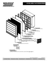
5. BREAKAWAY DUCT/SLEEVE CONNECTIONS:Rectangular ducts must use one or more of the followingconnects if the gauge is less than the requirement in Note 2 forrigid connections.A maximum of two #10 sheet metal screws on each side and onthe bottom, located in the center of the slip pocket andpenetrating both sides of the slip pocket may be used for ductsizes not exceeding 60” x 60” (1524 x 1524mm).One of the connections shown in Figure 9 on the top and bottomjoints with flat drive slip connections (shown in Figure 10) on theside joints may be used for dampers up to 20” (508mm) in height.Figure 9Figure 10Round or flat oval ducts connected to Type C, CR or CO damper collars may use #10 sheet metal screws as follows:• Duct diameters to 22" (558 mm) and smaller may use 3 screws, equally spaced around the circumference.• Duct diameters larger than 22" (558 mm) and up to 36" (914 mm) dia. may use 5 screws, equally spaced around thecircumference• Duct diameters larger than 36” (914 mm) may use eight screws, equally spaced around the circumference.NOTE: All breakaway connections described may have duct sealant, PA2048T duct sealant adhesive manufactured byPrecision, DP1010 water base duct sealant by Design Polymetrics, or Grey Pookie applied in accordance with SMACNArecommendations.Proprietary Flange System Breakaway Connections(Ductmate, Ward, Nexus)6 in. long 1/16 in. max.Flanged connection systems manufactured by Ductmate,Ward and Nexus are approved as breakaway connectionswhen installed as illustrated.Figure 10TDC by Lockformer , TDF by Engle:TDC and TDF systems are approved asbreakaway connections when installed as permanufacturer’s instructions using 6” (152mm)metal clips spaced as shown, gaskets and four3/8” (9.5mm) bolts and nuts (optional). Refer tothe SMACNA HVAC Duct ConstructionStandards and SMACNA Fire DamperInstallation Guide.Figure 115/2012 FD <strong>DYNAMIC</strong> IOM Page 3
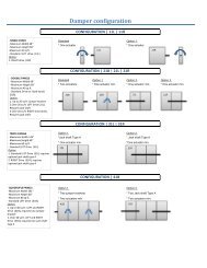
Damper MaintenanceDampers shall be maintained, cycled and tested in intervals as stated in the latest editions of NFPA 80 and 90A, unless localcodes require more frequent inspections.Dampers do not usually require maintenance as long as they are kept dry and clean. If cleaning is required use milddetergents or solvents. Do not use oil-based lubricants or any other lubricants that attract and retain contaminants such asdust.Trouble Shooting ChartSymptom Possible Cause Corrective ActionDamper does not fully open and or fullycloseFrame is out of square causing bladesto bind on track or jamb.Adjust damper frame such that it issquare and there is no twisting.Contaminants on damperClean blades with a non oil basedsolvent.Screws in damper blade track.Find screws in the damper blade trackand remove.Blades will not stay open Link melted by heat. Replace Link.• <strong>FOR</strong> SINGLE-SIDE RETAINING ANGLE <strong>INSTALLATION</strong> REFER TO ALUMAVENT SINGLE-SIDE RETAINING ANGLESSUPPLEMENTARY <strong>INSTALLATION</strong> <strong>INSTRUCTIONS</strong> FD-SSRA.195 HEALEY ROAD | BOLTON, ON. L7E 5B2 | TEL (905) 857-4700 | FAX (905) 857-4730 | 1-800-668-7214 | www.ventexinc.com5/2012 FD <strong>DYNAMIC</strong> IOM Page 4