Megger DLRO200 Low Resistance Testing - Actoolsupply.com
Megger DLRO200 Low Resistance Testing - Actoolsupply.com
Megger DLRO200 Low Resistance Testing - Actoolsupply.com
- No tags were found...

You also want an ePaper? Increase the reach of your titles
YUMPU automatically turns print PDFs into web optimized ePapers that Google loves.
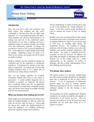
www.actoolsupply.<strong>com</strong>EVALUATION/INTERPRETATION OF RESULTSRepeatabilityA good quality low resistance ohmmeter will providerepeatable readings within the accuracy specifications forthe instrument. A typical accuracy specification is ±0.2%of reading, ±2 lsd (least significant digit). For a reading of1500.0, this accuracy specification allows a variance of±3.2 (0.2% x 1500 = 3; 2 lsd = 0.2).Additionally, the temperature coefficient must be factoredinto the reading if the ambient temperature deviates from thestandard calibration temperature.Spot Readings/Base Expectations for ReadingsSpot readings can be very important in understanding thecondition of an electrical system. The operator should havesome idea of the level of the expected measurement basedon the system’s data sheet or the supplier’s nameplate. Usingthis information as a baseline, variances can be identified andanalyzed. A <strong>com</strong>parison can also be made with data collectedon similar equipment.As noted, the data sheet or nameplate on a device shouldinclude electrical data relevant to its operation. The voltage,current and power requirements can be used to estimate theresistance of a circuit, and the operating specification can beused to determine the allowed change in a device (forexample, with battery straps, connection resistances willchange with time). Various national standards provideguidance for periodic test cycles.The temperature of the device will have a strong influence onthe expected reading. As an example, the data collected on ahot motor will be different from a cold reading at the time ofthe installation. As the motor warms up, the resistancereadings will go up. The resistance of copper windingsresponds to changes in temperature based on the basicnature of copper as a material. A more detailed review oftemperature effects is covered in the appendix. Using thenameplate data for a motor, the expected percentage changein resistance due to temperature can be estimated using thetable shown to the right for copper windings or the equationon which it is based.Different materials will have different temperaturecoefficients. As a result, the temperature correction equationwill vary depending on the material being tested.Copper – Temperature/<strong>Resistance</strong> RelationshipTemp. Temp. <strong>Resistance</strong> PercentºF ºC µΩ ChangeTrending-40º -40º 764.2 µΩ -23.6%32º 0º 921.5 µΩ -7.8%68º 20º 1000.0 µΩ 0.0%104º 40º 1078.6 µΩ +7.9%140º 60º 1157.2 µΩ +15.7%176º 80º 1235.8 µΩ +23.6%212º 100º 1314.3 µΩ +31.4%221º 105º 1334.0 µΩ +33.4%R (end of test) /R (beginning of test)= (234.5 + T (end of test) )/(234.5 + T (beginning of test)In addition to <strong>com</strong>paring measurements made with a lowresistance ohmmeter against some preset standard (spot test),the results should be saved and tracked against past andfuture measurements. Logging of measurements on standardforms with the data registered in a central database willimprove the efficiency of the testing operation. Prior test datacan be reviewed by the operator, and then on-site conditionscan be determined.Developing a trend of readings helps the operator betterpredict when a joint, weld, connection, or other <strong>com</strong>ponentwill be<strong>com</strong>e unsafe, and make the necessary fix(es).Remember that degradation can be a slow process. Electricalequipment faces mechanical operations or thermal cycles thatcan fatigue the leads, contacts and bond connections.Additionally, these <strong>com</strong>ponents may also be exposed tochemical attack from either the atmosphere or man-madesituations. Periodic testing and recording of the resultsprovides a database of values that can be used to developresistance trends.Note: When taking periodic measurements, theoperator should always connect the probes in the sameplace on the test sample to ensure similar testconditions.Following are several examples of where trending can helpthe operator make better-informed maintenance decisions:Circuit BreakersAs noted previously, mechanical wear and tear on circuitbreaker contacts that reduces the area of the contact surfaces<strong>com</strong>bined with sparking and/or arcing will increase theresistance across the working connections. This condition willproduce heat that can reduce the effectiveness of the circuitbreaker. Periodic measurements will show the rate of increaseof the contact resistance value. When these values are<strong>com</strong>pared to the original manufacturer’s specification, adecision can be made to continue or repair. By tracking thetrend of the readings, the operator will get an idea of whenthe circuit breaker should be pulled for service before damageis done.Stand-by Battery Back-up SystemsThe interface between the terminals and the straps on batteryback-up systems is subject to chemical attack from the acidatmosphere, thermal changes due to the charging anddischarge currents and mechanical stress from vibration. Eachof these factors can cause the resistance bond to degrade,resulting in the potential for a fire at a critical powerdischarge (due to the hydrogen gas atmosphere). Batterysystems require diligent attention, as replacement batteriesare both expensive and not off-the-shelf items. A failuresituation can result in a battery system being out of servicefor a number of weeks. Periodic measurements of the strapresistance will identify those bondconnections that have degraded since thelast test and corrective action can beplanned.Note: When connections have higherthan normal resistance measurements,the operator should not retighten thebolts, as this will over stress the soft leadconnection. Over tightening does notcure the problem. The proper procedureis to disassemble the straps, clean,grease and then reconnect with thebolts tightened to the supplier’s torquelevel. All the connections should bebalanced within a narrow tolerance of±10 to 20%.<strong>Resistance</strong> - Micro-Ohms140.0135.0130.0125.0120.0115.0123.00In these and many other systems, time lost to repair defectiveequipment may be small <strong>com</strong>pared to the cost of havingequipment out of service for weeks. Periodic testing can avertmany problems. Analyzing data against past results andreasonable standards allows the operator to select the timewhen corrective work should be done.The value of a system is in its ability to perform on demand.Operations are predicated on many systems being available atan instant’s notice. When elements break, production is lostand time is wasted making emergency repairs. Taking andanalyzing periodic low resistance measurements saves<strong>com</strong>panies money by helping identify problems before theyresult in catastrophic failure.The practical example shown in Figure 15 shows howtrending low resistance measurements made on a periodicbasis provides critical information to the operator. When lowresistance measurements are made on stranded cables onspot welding robot #23, the operator is gathering data toestimate when fatigue to the current conductor will degradethe quality of the weld nugget. The test data begins with thewire manufacturer’s specifications. It has been determinedthat a resistance increase of up to 10% is acceptable. In thiscase, measurements are made after a specific number ofweld operations. When charting this data, observe the rate ofchange as the readings approach the end of life for thestranded cable (see Figure 15). The critical factor could havebeen long-term exposure to a chemical solvent. In otheroperations the critical factor is time, with testing performedseasonal or on specified number of days.Allow for a 10% increase;5,000123.0 x 1.1 = 135.3;Scheduled <strong>Resistance</strong> Readings - Robot #23100-105K operations10,00015,00020,00025,00030,00035,00040,00045,00050,00055,00060,000Number of Operations65,00070,00075,00080,000Area of Concern85,00090,000132.995,000134.1100,000136.0105,000Figure 15: Trending Analysis of <strong>Low</strong> <strong>Resistance</strong> Readings14 A GUIDE TO LOW RESISTANCE TESTINGwww.actoolsupply.<strong>com</strong>A GUIDE TO LOW RESISTANCE TESTING 15