Solenoid valves Type EVR 2 → 40 NC/ NO
Solenoid valves Type EVR 2 → 40 NC/ NO
Solenoid valves Type EVR 2 → 40 NC/ NO

Create successful ePaper yourself
Turn your PDF publications into a flip-book with our unique Google optimized e-Paper software.
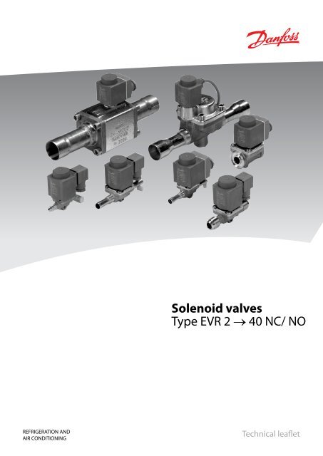
<strong>Solenoid</strong> <strong>valves</strong><strong>Type</strong> <strong>EVR</strong> 2 <strong>→</strong> <strong>40</strong> <strong>NC</strong>/ <strong>NO</strong>REFRIGERATION ANDAIR CONDITIONINGTechnical leaflet
Technical leaflet<strong>Solenoid</strong> <strong>valves</strong> type <strong>EVR</strong> 2 <strong>→</strong> <strong>40</strong> − <strong>NC</strong> / <strong>NO</strong>2 DKRCCPDBB0A302-520H1275 © Danfoss A/S (AC-AKS / frz),, 05 - 2008
Technical leaflet<strong>Solenoid</strong> <strong>valves</strong> type <strong>EVR</strong> 2 <strong>→</strong> <strong>40</strong> − <strong>NC</strong> / <strong>NO</strong>ContentsPageIntroduction....................................................................................... 4Features........................................................................................... 4Approvals ......................................................................................... 4Technical data ................................................................................... 4-5Ordering ........................................................................................ 6-8Liquid capacity Q o kW, R22/ R134a/R<strong>40</strong>4A/R507. .................................................... 9Liquid capacity Q o kW, R<strong>40</strong>7C ..................................................................... 10Suction vapour capacity Q o kW, R22 .............................................................. 10Suction vapour capacity Q o kW, R134a/R<strong>40</strong>4A/R507. ............................................... 11Suction vapour capacity Q o kW, R<strong>40</strong>7C ............................................................ 12Hot gas capacity Q h kW, R22. ...................................................................... 13Hot gas capacity Q h kW, R134a .................................................................... 14Hot gas capacity Q h kW, R<strong>40</strong>4A/R507 .............................................................. 15Hot gas capacity Q h kW, R<strong>40</strong>7C . . . . . . . . . . . . . . . . . . . . . . . . . . . . . . . . . . . . . . . . . . . . . . . . . . . . . . . . . . . . . . . . . . . . 16Hot gas capacity G h kg/s, R22/R134a. .............................................................. 17Hot gas capacity G h kg/s, R<strong>40</strong>4A/R507/R<strong>40</strong>7C ...................................................... 18Design/ Function ................................................................................. 19Material specification . . . . . . . . . . . . . . . . . . . . . . . . . . . . . . . . . . . . . . . . . . . . . . . . . . . . . . . . . . . . . . . . . . . . . . . . . . . . . 20Dimensions and weight, <strong>EVR</strong> (<strong>NC</strong>) 2 <strong>→</strong> 15 and <strong>EVR</strong> 6 -> 15 (<strong>NO</strong>) with fl are connection .............. 21Dimensions and weight, <strong>EVR</strong> (<strong>NC</strong>) 2 <strong>→</strong> 22 and <strong>EVR</strong> 6 -> 22 (<strong>NO</strong>) with solder connection ............. 22Dimensions and weight, <strong>EVR</strong> (<strong>NC</strong>) 25, 32 og <strong>40</strong> with solder connection ............................. 23© Danfoss A/S (AC-AKC / frz, 05 - 2008 DKRCCPDBB0A302-520H1275 3
Technical leaflet<strong>Solenoid</strong> <strong>valves</strong> type <strong>EVR</strong> 2 <strong>→</strong> <strong>40</strong> − <strong>NC</strong> / <strong>NO</strong>Introduction<strong>EVR</strong> is a direct or servo operated solenoidvalve for liquid, suction, and hot gas lines withfluorinated refrigerants.<strong>EVR</strong> <strong>valves</strong> are supplied complete or as separatecomponents, i.e. valve body, coil and flanges, ifrequired, can be ordered separately.FeaturesApprovalsTechnical data• Complete range of solenoid <strong>valves</strong> forrefrigeration, freezing and air conditioningplant• Supplied both normally closed (<strong>NC</strong>) andnormally open (<strong>NO</strong>) with de-energized coil• Wide choice of coils for a.c. and d.c.• Suitable for all fluorinated refrigerants• Designed for media temperatures up to105°CDnV, Det norske Veritas, NorgePressure Equipment Directive (PED) 97/23/ECThe Low Voltage Directive (LVD) 73/23/EC withamendments EN 60730-2-8RefrigerantsCFC, HCFC, HFCTemperature of medium−<strong>40</strong> <strong>→</strong> +105°C with 10 W or 12 W coil.Max. 130°C during defrosting.• MOPD up to 25 bar with 12 W coil• Flare connections up to 5/8 in.• Solder connections up to 2 1/8 in.• Extended ends for solderingmake installation easyIt is not necessary to dismantle the valvewhen soldering in.• <strong>EVR</strong> are also available with flangeconnectionsPolski Rejestr Statków, PolenMRS, Maritime Register of Shipping, RussiaVersions with UL approval can be supplied toorder.Ambient temperature andenclosure for coilSee "Coils for solenoid <strong>valves</strong>", RD.3J.E2.024 DKRCCPDBB0A302-520H1275 © Danfoss A/S (AC-AKS / frz),, 05 - 2008
Technical leaflet<strong>Solenoid</strong> <strong>valves</strong> type <strong>EVR</strong> 2 <strong>→</strong> <strong>40</strong> − <strong>NC</strong> / <strong>NO</strong>Technical data(continued)<strong>Type</strong>Min.Opening differential pressurewith standard coil∆p barMax. (= MOPD) liquid 2 )10 W a. c. 12 W a. c. 20 W d. c.Temperatureof medium°CMax. workingpressurePBbark v value 1 )<strong>EVR</strong> 2 0.0 25 18 −<strong>40</strong> <strong>→</strong> 105 45.2 0.16<strong>EVR</strong> 3 0.0 21 25 18 −<strong>40</strong> <strong>→</strong> 105 45.2 0.27<strong>EVR</strong> 6 0.05 21 25 18 −<strong>40</strong> <strong>→</strong> 105 35 0.8<strong>EVR</strong> 6 <strong>NO</strong> 0.05 21 21 21 −<strong>40</strong> <strong>→</strong>105 35 0.8<strong>EVR</strong> 10 0.05 21 25 18 −<strong>40</strong> <strong>→</strong> 105 35 1.9<strong>EVR</strong> 10 <strong>NO</strong> 0.05 21 21 21 −<strong>40</strong> <strong>→</strong> 105 35 1.9<strong>EVR</strong> 15 0.05 21 25 18 −<strong>40</strong> <strong>→</strong> 105 32 2.6<strong>EVR</strong> 15 <strong>NO</strong> 0.05 21 21 21 −<strong>40</strong> <strong>→</strong> 105 32 2.6<strong>EVR</strong> 20 (a.c.) 0.05 21 25 13 −<strong>40</strong> <strong>→</strong> 105 32 5.0<strong>EVR</strong> 20 (d.c.) 0.05 16 −<strong>40</strong> <strong>→</strong> 105 32 5.0<strong>EVR</strong> 20 <strong>NO</strong> 0.05 19 19 19 −<strong>40</strong> <strong>→</strong> 105 32 5.0<strong>EVR</strong> 22 0.05 21 25 13 −<strong>40</strong> <strong>→</strong> 105 32 6.0<strong>EVR</strong> 22 <strong>NO</strong> 0.05 19 19 19 −<strong>40</strong> <strong>→</strong> 105 32 6.0<strong>EVR</strong> 25 3) 0.20 21 25 18 −<strong>40</strong> <strong>→</strong> 105 32 10.0<strong>EVR</strong> 32 3) 0.20 21 25 18 −<strong>40</strong> <strong>→</strong> 105 32 16.0<strong>EVR</strong> <strong>40</strong> 3) 0.20 21 25 18 −<strong>40</strong> <strong>→</strong> 105 32 25.01) The k v value is the water flow in m 3 /h at a pressure drop across valve of 1 bar, ρ = 1000 kg/m 3 .2) MOPD for media in gas form is approx. 1 bar greater.3)Min. diff. pressure 0.07 bar is needed to stay open.m 3 /h<strong>Type</strong>Rated capacitykWLiquid Suction vapour Hot gasR22 R134a R<strong>40</strong>4A/R507 R<strong>40</strong>7C R22 R134a R<strong>40</strong>4A/R 507 R<strong>40</strong>7C R22 R134a R<strong>40</strong>4A/R507 R<strong>40</strong>7C<strong>EVR</strong> 2 3.20 2.90 2.20 3.01 1.50 1.20 1.20 1.46<strong>EVR</strong> 3 5.<strong>40</strong> 5.00 3.80 5.08 2.50 2.00 2.00 2.43<strong>EVR</strong> 6 16.10 14.80 11.20 15.13 1.80 1.30 1.60 1.66 7.<strong>40</strong> 5.90 6.00 7.18<strong>EVR</strong> 10 38.20 35.30 26.70 35.91 4.30 3.10 3.90 3.96 17.50 13.90 14.30 16.98<strong>EVR</strong> 15 52.30 48.30 36.50 49.16 5.90 4.20 5.30 5.43 24.00 19.00 19.60 23.28<strong>EVR</strong> 20 101.00 92.80 70.30 94.94 11.<strong>40</strong> 8.10 10.20 10.49 46.20 36.60 37.70 44.81<strong>EVR</strong> 22 121.00 111.00 84.30 113.74 13.70 9.70 12.20 12.60 55.<strong>40</strong> 43.90 45.20 53.74<strong>EVR</strong> 25 201.00 186.00 141.00 188.94 22.80 16.30 20.<strong>40</strong> 20.98 92.30 73.20 75.30 89.53<strong>EVR</strong> 32 322.00 297.00 225.00 302.68 36.50 26.10 32.60 33.58 148.00 117.00 120.00 143.56<strong>EVR</strong> <strong>40</strong> 503.00 464.00 351.00 472.82 57.00 <strong>40</strong>.80 51.00 52.44 231.00 183.00 188.00 224.07Rated liquid and suction vapour capacity is based onevaporating temperature t e = -10°C,liquid temperature ahead of valve t l = +25°C,pressure drop in valve ∆p = 0.15 bar.Rated hot gas capacity is based oncondensing temperature t c = +<strong>40</strong>°C,pressure drop across valve ∆p = 0.8 bar,hot gas temperature t h = +65°C,and subcooling of refrigerant ∆t sub = 4 K.© Danfoss A/S (AC-AKC / frz, 05 - 2008 DKRCCPDBB0A302-520H1275 5
Technical leaflet<strong>Solenoid</strong> <strong>valves</strong> type <strong>EVR</strong> 2 <strong>→</strong> <strong>40</strong> − <strong>NC</strong> / <strong>NO</strong>OrderingComplete <strong>valves</strong>Normally closed (<strong>NC</strong>) with a.c. coil 1 )<strong>Type</strong>ConnectionCode no.Valve body + 10 W a. c. coil with 1 m cableFlare 2 )Solder ODFin. mm in./mm in. mm<strong>EVR</strong> 3 1/ 4 6 032F8109 032F2042 032F2052<strong>EVR</strong> 6 3/ 8 10 032F8073 032F2082 032F2092<strong>EVR</strong> 10 1/ 2 12 032F8091 032F2122 032F2132<strong>EVR</strong> 15 5/ 8 16 032F8102 032F2192 032F2192<strong>Type</strong>ConnectionCode no.Valve body + 10 W a. c. coil with terminal boxFlare 2 )Solder ODFin. mm in./mm in. mm<strong>EVR</strong> 3 1/ 4 6 032F8110 032F2043 032F2053<strong>EVR</strong> 6 3/ 8 10 032F8074 032F2083 032F2093<strong>EVR</strong> 10 1/ 2 12 032F8092 032F2123 032F2133<strong>EVR</strong> 15 5/ 8 16 032F8103 032F2193 032F2193<strong>EVR</strong> 20 7/ 8 22 032F2243 032F22431) Please specify code no., voltage and frequency. Voltage and frequency can also be given in the form of anappendix number, see table "Appendix numbers".2) Supplied without flare nuts.Separate flare nuts:1/ 4 in. or 6 mm, code no. 011L11013/ 8 in. or 10 mm, code no. 011L11351/ 2 in. or 12 mm, code no. 011L11035/ 8 in. or 16 mm, code no. 011L11673) Can only be used with DIN plugAppendix numbersVoltageV12244248115220-2302<strong>40</strong>380-<strong>40</strong>0420241152202<strong>40</strong>110220-230FrequencyHz5050505050505050506060606050/6050/60Energy consumpt.W101010101010101010101010101010Appendix no.1516171822313337381420293021326 DKRCCPDBB0A302-520H1275 © Danfoss A/S (AC-AKS / frz),, 05 - 2008
Technical leaflet<strong>Solenoid</strong> <strong>valves</strong> type <strong>EVR</strong> 2 <strong>→</strong> <strong>40</strong> − <strong>NC</strong> / <strong>NO</strong>Ordering (continued)ComponentsFlare and solder connectionsSeparate valve bodies, normally closed (<strong>NC</strong>)<strong>Type</strong>Requiredcoil typeConnectionFlare 1 )in. mm in./mm in. mmCode no.<strong>EVR</strong> 2 a.c. 1/ 4 6 032F8056 032F1201 032F1202<strong>EVR</strong> 3<strong>EVR</strong> 61/ 4 6 032F8107 032F1206 032F12073/ 8 10 032F8116 032F1204 032F12083/ 8 10 032F8072 032F1212 032F12131/ 2 12 032F8079 032F1209 032F1236Solder ODF With manualValve body without coilWith manualoperationWithout manualoperation<strong>EVR</strong> 10a.c./d.c.1/ 2 12 032F8095 032F1217 032F12185/ 8 16 032F8098 032F1214 032F12145/ 8 16 032F8101 032F1228 032F1228<strong>EVR</strong> 155/ 8 16 032F8100 2 ) 032F12277/ 8 22 032F1225 032F12257/ 8 22 032F12<strong>40</strong> 032F12<strong>40</strong>a.c.7/ 8 22 032F1254<strong>EVR</strong> 201 1 / 8 28 032F1244 032F1245d.c.7/ 8 22 032F1264 032F12647/ 8 22 032F1274<strong>EVR</strong> 22 a.c. 1 3 / 8 35 032F3267 032F32671 1 / 8 032F2200 032F2201<strong>EVR</strong> 2528 032F2205 032F22061 3 / 8 35 032F2207 032F22081 3 / 8 35 042H1105 042H1106<strong>EVR</strong> 32a.c./d.c. 1 5 / 8 042H1103 042H110442 042H1107 042H11081 5 / 8 042H1109 042H1110<strong>EVR</strong> <strong>40</strong>42 042H1113 042H11142 1 / 8 54 042H1111 042H1112Separate valve bodies, normally open (<strong>NO</strong>) 3 )<strong>Type</strong><strong>EVR</strong> 6Requiredcoil typea.c./d.c.Connection1) Valve bodies are supplied without flare nuts.Separate flare nuts:1/ 4 in. or 6 mm, code no. 011L11013/ 8 in. or 10 mm, code no. 011L11351/ 2 in. or 12 mm, code no. 011L11035/ 8 in. or 16 mm, code no. 011L11672) With manual operation.3) The normal range of coils can be used for the <strong>NO</strong> <strong>valves</strong>, with the exception of the doublefrequency versions of 110 V, 50/60 Hz and 220 V, 50/60 Hz.CoilsSee "Coils for solenoid <strong>valves</strong>", RD.3J.E2.02.Flare 1 )Code no.Valve body without coil 3 )Solder ODFin. mm in. mm in. mm3/ 8 10 032F8085 032F8085 032F1290 032F1295<strong>EVR</strong> 10 1/ 2 12 032F8090 032F8090 032F1291 032F1296<strong>EVR</strong> 15<strong>EVR</strong> 205/ 8 16 032F8099 032F8099 032F1299 032F12997/ 8 22 032F3270 032F32707/ 8 22 032F1260 032F12601 1 / 8 28 032F1269 032F1279<strong>EVR</strong> 22 a.c. 1 3 / 8 35 032F3268 032F3268© Danfoss A/S (AC-AKC / frz, 05 - 2008 DKRCCPDBB0A302-520H1275 7
Technical leaflet<strong>Solenoid</strong> <strong>valves</strong> type <strong>EVR</strong> 2 <strong>→</strong> <strong>40</strong> − <strong>NC</strong> / <strong>NO</strong>Ordering (continued)ComponentsFlare and solder connectionsSeparate valve bodies, normally closed (<strong>NC</strong>)<strong>EVR</strong> 15<strong>EVR</strong> 20<strong>Type</strong> Require coil type Connectiona.c./d.c.Code no.Valve body + gaskets +bolts;without coil and flangesWithout manualoperation032F1234Without manualoperation032F1224a.c. Flanges032F1253 032F1243d.c. 032F1273 032F1263CoilsSee "Coils for solenoid <strong>valves</strong>", RD.3J.E2.02.Flange setsValve type<strong>EVR</strong> 15<strong>EVR</strong> 20ConnectionCode no.SolderWeidin. mm in. mm in.1/ 2 027N11155/ 8 16 027L1117 027L11163/ 4 027N11207/ 8 22 027L1123 027L11223/ 4 027N12207/ 8 22 027L1223 027L12221 027N12251 1 / 8 28 027L1229 027L1228Example<strong>EVR</strong> 15 without manual operation,code no. 032F1224+ 1/2 in. weld flange set,code no. 027N1115+ coil with termfnal box, 220 V, 50 Hz,code no. 018F6701(See "Coils for solenoid <strong>valves</strong>",RD.3J.E2.02.).AccessoriesDescriptionMounting bracket for <strong>EVR</strong> 2, 3, 6 and 10Strainer FA for direct mountingCode no.032F0197See "FA"8 DKRCCPDBB0A302-520H1275 © Danfoss A/S (AC-AKS / frz),, 05 - 2008
Technical leafletCapacity<strong>Solenoid</strong> <strong>valves</strong> type <strong>EVR</strong> 2 <strong>→</strong> <strong>40</strong> − <strong>NC</strong> / <strong>NO</strong>Liquid capacity Q e kW<strong>Type</strong>Liquid capacity Q e kW at pressure drop across valve ∆p bar0.1 0.2 0.3 0.4 0.5<strong>EVR</strong> 2 2.6 3.7 4.6 5.3 5.9<strong>EVR</strong> 3 4.5 6.3 7.7 8.9 9.9<strong>EVR</strong> 6 13.1 18.6 22.8 26.3 29.4<strong>EVR</strong> 10 31.4 44.1 54.2 62.5 69.9<strong>EVR</strong> 15 42.7 60.3 74.1 85.5 95.7<strong>EVR</strong> 20 82.2 116.0 143.0 165.0 184.0<strong>EVR</strong> 22 99.0 139.0 171.0 197.0 220.0<strong>EVR</strong> 25 165.0 232.0 285.0 329.0 368.0<strong>EVR</strong> 32 263.0 372.0 455.0 526.0 588.0<strong>EVR</strong> <strong>40</strong> 411.0 581.0 712.0 822.0 919.0R22Liquid capacity Q e kW<strong>Type</strong>Capacities are based onliquid temperature t l = +25°C ahead of valve,evaporating temperature t e = −10°C,superheat 0 K.Correction factorsWhen sizing <strong>valves</strong>, the plant capacity must bemultiplied by a correctionfactor depending on liquid temperaturet l ahead of valve/evaporator.When the corrected capacity is known, theselection can be made from the table.Liquid capacity Q e kW at pressure drop across valve ∆p barR134a0.1 0.2 0.3 0.4 0.5<strong>EVR</strong> 2 2.4 3.4 4.2 4.9 5.4<strong>EVR</strong> 3 4.1 5.8 7.1 8.2 9.1<strong>EVR</strong> 6 12.1 17.2 21.0 24.3 27.1<strong>EVR</strong> 10 28.8 <strong>40</strong>.7 49.9 57.6 64.4<strong>EVR</strong> 15 39.4 55.7 68.3 78.8 88.1<strong>EVR</strong> 20 75.8 107.0 131.0 152.0 170.0<strong>EVR</strong> 22 90.9 129.0 158.0 182.0 203.0<strong>EVR</strong> 25 152.0 214.0 263.0 303.0 339.0<strong>EVR</strong> 32 243.0 343.0 420.0 485.0 542.0<strong>EVR</strong> <strong>40</strong> 379.0 536.0 656.0 758.0 847.0Liquid capacity Q e kW<strong>Type</strong>Liquid capacity Q e kW at pressure drop across valve ∆p barR<strong>40</strong>4A/R5070.1 0.2 0.3 0.4 0.5<strong>EVR</strong> 2 1.8 2.6 3.2 3.7 4.1<strong>EVR</strong> 3 3.1 4.4 5.4 6.2 6.9<strong>EVR</strong> 6 9.2 13.0 15.9 18.4 20.5<strong>EVR</strong> 10 21.8 30.8 37.8 43.6 48.8<strong>EVR</strong> 15 29.8 42.2 51.7 59.6 66.8<strong>EVR</strong> 20 57.4 81.1 99.4 115.0 128.0<strong>EVR</strong> 22 68.9 97.4 119.0 138.0 169.0<strong>EVR</strong> 25 115.0 162.0 199.0 230.0 257.0<strong>EVR</strong> 32 184.0 260.0 318.0 367.0 411.0<strong>EVR</strong> <strong>40</strong> 287.0 <strong>40</strong>6.0 497.0 574.0 642.0Correction factors for liquid temperature t lt l °C −10 0 10 15 20 25 30 35 <strong>40</strong> 45 50R22 0.76 0.82 0.88 0.92 0.96 1.0 1.05 1.10 1.16 1.22 1.30R134a 0.73 0.79 0.86 0.90 0.95 1.0 1.06 1.12 1.19 1.27 1.37R<strong>40</strong>4A/R507 0.65 0.72 0.81 0.86 0.93 1.0 1.09 1.20 1.33 1.51 1.74© Danfoss A/S (AC-AKC / frz, 05 - 2008 DKRCCPDBB0A302-520H1275 9
Technical leafletCapacity(continued)<strong>Solenoid</strong> <strong>valves</strong> type <strong>EVR</strong> 2 <strong>→</strong> <strong>40</strong> − <strong>NC</strong> / <strong>NO</strong>Liquid capacity Q e kWR<strong>40</strong>7C<strong>Type</strong>Liquid capacity Q e kW at pressure drop across valve ∆p bar0.1 0.2 0.3 0.4 0.5<strong>EVR</strong> 2 2.4 3.4 4.3 5.0 5.3<strong>EVR</strong> 3 4.2 5.9 7.2 8.4 9.3<strong>EVR</strong> 6 12.3 17.5 21.4 24.7 27.6<strong>EVR</strong> 10 29.5 41.5 50.9 58.7 65.7<strong>EVR</strong> 15 <strong>40</strong>.1 56.7 69.7 80.4 90.0<strong>EVR</strong> 20 77.0 109.0 134.0 155.0 172.0<strong>EVR</strong> 22 93.1 130.0 161.0 185.2 207.0<strong>EVR</strong> 25 155.0 218.0 268.0 309.0 346.0<strong>EVR</strong> 32 247.0 350.0 428.0 494.0 553.0<strong>EVR</strong> <strong>40</strong> 386.0 546.0 669.0 773.0 864.0Capacities are based on liquid temperaturet l = +25°C ahead of valve, evaporatingtemperature t e = −10°C, and superheat 0 K.Correction factorsWhen sizing <strong>valves</strong>, the plant capacity must bemultiplied by a correctionfactor depending on liquid temperaturet l ahead of valve/evaporator.When the corrected capacity is known, theselection can be made from the table.Correction factors based on liquid temperature t lt l °C −10 0 10 15 20 25 30 35 <strong>40</strong> 45 50R<strong>40</strong>7C 0.71 0.78 0.85 0.89 0.94 1.0 1.06 1.14 1.23 1.33 1.46Capacities are based on liquidtemperature t l = +25°C ahead ofevaporator.The table values refer to the evaporatorcapacity and are given as a functionof evaporating temperature t e andpressure drop ∆p across valve.Capacities are based on dry, saturatedvapour ahead of valve.During operation with superheatedvapour ahead of valve, the capacitiesare reduced by 4% for each 10 Ksuperheat.Suction vapour capacity Q e<strong>Type</strong><strong>EVR</strong> 6<strong>EVR</strong> 10<strong>EVR</strong> 15<strong>EVR</strong> 20<strong>EVR</strong> 22<strong>EVR</strong> 25<strong>EVR</strong> 32<strong>EVR</strong> <strong>40</strong>Pressure drop∆p bar0.10.150.20.10.150.20.10.150.20.10.150.20.10.150.20.10.150.20.10.150.20.10.150.2Suction vapour capacity Q e kW at evaporating temperature t e °C–<strong>40</strong> –30 –20 –10 0 +100.730.870.981.72.12.32.32.83.24.65.46.15.56.57.39.110.912.214.617.419.622.827.230.5Correction factorsWhen sizing <strong>valves</strong>, the evaporator capacity mustbe multiplied by a correction factor dependingon liquid temperature t l ahead of expansionvalve.When the corrected capacity is known, theselection can be made from the table.Correction factors for liquid temperature t l0.941.11.32.22.73.13.13.74.25.97.18.17.18.59.711.814.216.118.922.725.729.535.4<strong>40</strong>.21.21.41.62.93.43.94.04.75.37.69.110.39.110.712.315.217.920.424.328.832.638.145.051.01.51.82.03.54.34.84.85.96.69.311.412.711.213.715.218.622.825.329.836.5<strong>40</strong>.546.557.063.31.82.22.54.35.26.05.87.18.211.213.915.913.416.419.022.427.431.735.843.850.756.068.679.2t l °C −10 0 10 15 20 25 30 35 <strong>40</strong> 45 50R222.12.63.05.16.27.16.98.59.813.316.718.816.020.022.626.632.637.642.652.260.266.581.594.0R22 0.76 0.82 0.88 0.92 0.96 1.0 1.05 1.10 1.16 1.22 1.3010 DKRCCPDBB0A302-520H1275 © Danfoss A/S (AC-AKS / frz),, 05 - 2008
Technical leaflet<strong>Solenoid</strong> <strong>valves</strong> type <strong>EVR</strong> 2 <strong>→</strong> <strong>40</strong> − <strong>NC</strong> / <strong>NO</strong>Capacity(continued)Capacities are based on liquidtemperature t l = +25°C aheadof evaporator.The table values refer to theevaporator capacity andare given as a function ofevaporating temperature t e andpressure drop ∆p across valve.Capacities are based on dry,saturated vapour ahead ofvalve.During operation withsuperheated vapour aheadof valve, the capacities arereduced by 4% for each 10 Ksuperheat.Suction vapour capacity Q e<strong>Type</strong><strong>EVR</strong> 6<strong>EVR</strong> 10<strong>EVR</strong> 15<strong>EVR</strong> 20<strong>EVR</strong> 22<strong>EVR</strong> 25<strong>EVR</strong> 32<strong>EVR</strong> <strong>40</strong>Pressure dropacross valve ∆p bar0.10.150.20.10.150.20.10.150.20.10.150.20.10.150.20.10.150.20.10.150.20.10.150.2Suction vapour capacity Q e kW<strong>Type</strong><strong>EVR</strong> 6<strong>EVR</strong> 10<strong>EVR</strong> 15<strong>EVR</strong> 20<strong>EVR</strong> 22<strong>EVR</strong> 25<strong>EVR</strong> 32<strong>EVR</strong> <strong>40</strong>Pressure dropacross valve ∆p bar0.10.150.20.10.150.20.10.150.20.10.150.20.10.150.20.10.150.20.10.150.20.10.150.2Suction vapour capacity Q e kW at evaporating temperature t e °CR134a–<strong>40</strong> –30 –20 –10 0 +100.460.530.581.11.31.41.51.71.92.93.33.73.44.04.45.86.67.39.310.611.714.516.518.30.730.870.981.72.12.32.32.83.24.65.46.15.56.57.39.110.912.214.617.419.622.827.230.50.841.01.12.02.42.72.73.33.75.36.37.16.37.58.510.512.514.116.820.022.626.331.335.31.11.31.52.63.13.53.64.24.87.08.19.38.39.711.113.916.318.522.226.129.634.8<strong>40</strong>.846.31.41.71.93.34.04.54.55.56.18.610.611.710.312.714.017.221.123.427.733.837.443.352.858.51.72.02.44.04.95.75.56.77.810.613.015.012.715.517.921.125.929.933.841.447.452.864.874.8R<strong>40</strong>4A/R507Suction vapour capacity Q e kW at evaporating temperature t e °C–<strong>40</strong> –30 –20 –10 0 +100.620.730.821.51.72.02.02.42.73.94.65.24.65.56.27.79.110.312.314.616.519.322.825.80.80.971.11.92.32.62.63.23.65.06.16.96.07.38.310.112.113.816.219.422.025.330.334.51.11.31.42.53.03.43.54.14.76.77.99.08.09.510.813.315.818.021.325.328.833.339.545.01.31.61.83.23.94.34.35.35.98.310.211.410.012.213.616.620.422.726.632.636.341.551.056.81.62.02.33.94.85.55.36.57.510.212.514.412.215.017.320.425.028.832.6<strong>40</strong>.046.151.062.572.12.02.42.84.75.86.76.47.99.112.315.217.514.818.221.024.630.335.039.448.556.061.575.687.5Correction factorsWhen sizing <strong>valves</strong>, the plant capacity must bemultiplied by a correctionfactor depending on liquid temperaturet l ahead of valve/evaporator.When the corrected capacity is known, theselection can be made from the table.Correction factors based on liquid temperature t lt l °C −10 0 10 15 20 25 30 35 <strong>40</strong> 45 50R134a 0.73 0.79 0.86 0.90 0.95 1.0 1.06 1.12 1.19 1.27 1.37R<strong>40</strong>4A/R507 0.65 0.72 0.81 0.86 0.93 1.0 1.09 1.20 1.33 1.51 1.74© Danfoss A/S (AC-AKC / frz, 05 - 2008 DKRCCPDBB0A302-520H1275 11
Technical leaflet<strong>Solenoid</strong> <strong>valves</strong> type <strong>EVR</strong> 2 <strong>→</strong> <strong>40</strong> − <strong>NC</strong> / <strong>NO</strong>Capacity(continued)<strong>Type</strong>Pressure dropacross valve ∆p barSuction vapour capacity Q e kW at evaporating temperature t e °CR<strong>40</strong>7C–<strong>40</strong> –30 –20 –10 0 +10<strong>EVR</strong> 60.10.150.20.610.720.810.810.951.11.11.31.41.41.71.81.72.12.42.02.52.9<strong>EVR</strong> 100.10.150.21.41.71.91.92.32.72.63.03.53.24.04.44.04.95.64.96.06.9<strong>EVR</strong> 150.10.150.21.92.32.72.73.23.63.64.24.74.45.46.15.56.77.76.78.29.5Capacities are based on liquidtemperature t l = +25°C ahead ofevaporator.The table values refer to theevaporator capacity and are givenas a function of evaporatingtemperature t e and pressure drop ∆pacross valve.Capacities are based on dry,saturated vapour ahead of valve.During operation with superheatedvapour ahead of valve, the capacitiesare reduced by 4% for each 10 Ksuperheat.<strong>EVR</strong> 20<strong>EVR</strong> 22<strong>EVR</strong> 25<strong>EVR</strong> 32<strong>EVR</strong> <strong>40</strong>0.10.150.20.10.150.20.10.150.20.10.150.20.10.150.23.84.55.14.65.46.17.69.110.112.114.416.318.922.625.35.16.17.06.17.38.310.212.213.916.319.522.125.430.434.66.88.19.28.19.511.013.515.918.221.625.629.033.9<strong>40</strong>.145.48.610.511.710.312.614.017.121.023.327.433.637.342.852.458.210.513.114.912.615.417.921.125.829.833.741.247.752.664.574.412.916.218.215.519.421.925.831.636.541.350.658.464.579.191.2Correction factorsWhen sizing <strong>valves</strong>, the evaporator capacitymust be multiplied by a correction factor depending on liquid temperaturet l ahead of expansion valve. When the corrected capacity is known, theselection can be made from the table.Correction factors based on liquid temperature t lt l °C −10 0 10 15 20 25 30 35 <strong>40</strong> 45 50R<strong>40</strong>7C 0.71 0.78 0.85 0.89 0.94 1.0 1.06 1.14 1.23 1.33 1.46Hot gas defrostingWith hot gas defrosting it is not normally possibleto select a valve from condensing temperature t cand evaporating temperature t e .This is because the pressure in the evaporatoras a rule quickly rises to a value near that of thecondensing pressure. It remains at this valueuntil the defrosting is finished.In most cases therefore, the valve will be selectedfrom condensing temperature t c and pressuredrop ∆p across the valve, as shown in theexample for heat recovery.Heat recoveryThe following is given:Refrigerant = R22Evaporating temperature t e = – 30°CCondensing temperature t c = + <strong>40</strong>°CHot gas temperature ahead of valve t h = + 85°CHeat recovery condenser yield Q h = 8 kWThe capacity table for 22 with t c = + <strong>40</strong>°C givesthe the capacity for an <strong>EVR</strong> 10 as 8.9 kW, whenpressure drop ∆p is 0.2 bar.The correction factor for t e = – 30°C is given in thetable as 0.94.The correction for hot gas temperaturet h = + 85°C has been calculated as 4% whichcorresponds to a factor of 1.04.Q h must be corrected with factors found:With ∆p = 0.2 bar isQ h = 8.9 x 0.94 x 1.04 = 8.7 kW.With ∆p = 0.1 bar, Q h becomes only6.3 x 0.94 x 1.04 = 6.2 kW.An <strong>EVR</strong> 6 would also be able to give the requiredcapacity, but with ∆p at approx. 1 bar.The <strong>EVR</strong> 6 is therefore too small.The <strong>EVR</strong> is so large that it is doubtful whether thenecessary ∆p of apprx. 0.1 bar could be obtained.An <strong>EVR</strong> 15 would therefore be too large.Result: An <strong>EVR</strong> 10 is the correct valve for thegiven conditions.12 DKRCCPDBB0A302-520H1275 © Danfoss A/S (AC-AKS / frz),, 05 - 2008
Technical leaflet<strong>Solenoid</strong> <strong>valves</strong> type <strong>EVR</strong> 2 <strong>→</strong> <strong>40</strong> − <strong>NC</strong> / <strong>NO</strong>Capacity(continued)An increase in hot gas temperaturet h of 10 K, based on t h = t c +25°C,reduces valve capacity approx. 2%and vice versa.A change in evaporating temperaturet e changes valve capacity; seecorrection factor table below.Hot gas capacity Q h kW<strong>Type</strong><strong>EVR</strong> 2<strong>EVR</strong> 3<strong>EVR</strong> 6<strong>EVR</strong> 10<strong>EVR</strong> 15<strong>EVR</strong> 20<strong>EVR</strong> 22<strong>EVR</strong> 25<strong>EVR</strong> 32<strong>EVR</strong> <strong>40</strong>Pressure dropacross valve∆p bar0.10.20.<strong>40</strong>.81.60.10.20.<strong>40</strong>.81.60.10.20.<strong>40</strong>.81.60.10.20.<strong>40</strong>.81.60.10.20.<strong>40</strong>.81.60.10.20.<strong>40</strong>.81.60.10.20.<strong>40</strong>.81.60.10.20.<strong>40</strong>.81.60.10.20.<strong>40</strong>.81.60.10.20.<strong>40</strong>.81.6Hot gas capacity Q h kWEvaporating temp. t e =-10°C. Hot gas temp. t h =t c +25°C. Subcooling ∆t sub =4 KCondensing temperature t c °C+20 +30 +<strong>40</strong> +50 +600.470.670.961.321.870.801.141.632.233.152.43.44.86.69.35.68.011.415.722.27.711.015.721.530.314.821.130.041.358.317.825.336.149.570.029.642.160.282.5117.047.467.496.3132.0187.074.0105.0151.0206.0291.00.500.711.021.371.990.851.201.722.313.352.53.65.16.89.96.08.512.116.223.68.211.616.622.232.315.722.331.942.762.118.826.838.351.274.531.444.663.887.9124.050.271.4102.01<strong>40</strong>.0199.078.5112.0159.0222.0310.00.530.751.071.482.080.891.261.802.493.522.63.75.37.410.46.38.912.717.524.88.612.117.324.033.916.523.433.346.265.219.728.0<strong>40</strong>.055.478.232.946.766.692.3130.052.674.7107.0148.0209.082.3117.0167.0231.0326.00.5<strong>40</strong>.771.101.572.160.921.301.852.653.642.73.45.57.910.86.59.213.018.725.68.812.517.825.535.017.024.134.349.167.420.428.941.258.980.834.048.268.698.2135.054.477.1110.0157.0216.085.0121.0172.0246.0337.0R220.550.781.111.592.190.931.321.872.683.692.83.95.67.910.96.59.313.218.926.08.912.718.025.935.517.224.434.749.668.420.629.341.659.582.034.448.869.499.2137.055.078.1111.0159.0219.086.0122.0174.0248.0342.0Correction factorsWhen sizing <strong>valves</strong>, the table value must bemultiplied by a correction factor depending onevaporating temperature t e .Correction factors for evaporating temperatur t et e °C −<strong>40</strong> −30 −20 −10 0 +10R22 0.90 0.94 0.97 1.0 1.03 1.05© Danfoss A/S (AC-AKC / frz, 05 - 2008 DKRCCPDBB0A302-520H1275 13
Technical leaflet<strong>Solenoid</strong> <strong>valves</strong> type <strong>EVR</strong> 2 <strong>→</strong> <strong>40</strong> − <strong>NC</strong> / <strong>NO</strong>Capacity(continued)An increase in hot gas temperaturet h of 10 K, based on t h = t c +25°C,reduces valve capacity approx. 2%and vice versa.A change in evaporating temperaturet e changes valve capacity; seecorrection factor table below.Hot gas capacity Q h kW<strong>Type</strong><strong>EVR</strong> 2<strong>EVR</strong> 3<strong>EVR</strong> 6<strong>EVR</strong> 10<strong>EVR</strong> 15<strong>EVR</strong> 20<strong>EVR</strong> 22<strong>EVR</strong> 25<strong>EVR</strong> 32<strong>EVR</strong> <strong>40</strong>Pressure dropacross valve∆p bar0.10.20.<strong>40</strong>.81.60.10.20.<strong>40</strong>.81.60.10.20.<strong>40</strong>.81.60.10.20.<strong>40</strong>.81.60.10.20.<strong>40</strong>.81.60.10.20.<strong>40</strong>.81.60.10.20.<strong>40</strong>.81.60.10.20.<strong>40</strong>.81.60.10.20.<strong>40</strong>.81.60.10.20.<strong>40</strong>.81.6Hot gas capacity Q h kWR134aEvaporating temp. t e =-10°C. Hot gas temp. t h =t c +25°C. Subcooling ∆t sub =4 KvCondensing temperature t c °C+20 +30 +<strong>40</strong> +50 +600.380.5<strong>40</strong>.741.061.500.6<strong>40</strong>.911.261.792.571.882.693.735.297.614.56.48.912.618.16.18.712.117.224.811.816.823.433.147.614.120.228.039.757.123.633.646.666.295.237.653.874.7106.0152.058.884.1117.0166.0238.00.<strong>40</strong>0.570.821.131.610.670.961.381.902.721.992.844.085.628.054.76.89.713.319.16.59.213.318.326.212.517.825.535.150.315.021.330.642.260.424.935.551.070.2101.039.856.881.6112.0161.062.388.8127.0176.0252.00.410.590.841.171.670.700.991.421.982.822.072.954.225.868.374.97.010.013.919.96.79.613.719.027.213.018.426.436.652.315.522.131.643.962.825.936.852.773.2105.041.458.984.3117.0167.064.792.1132.0183.0262.00.420.600.861.231.700.711.011.442.082.882.113.004.286.168.525.07.110.214.620.26.79.713.920.027.713.218.726.738.553.315.822.632.146.263.926.437.453.477.0107.042.159.885.4123.0170.065.893.5134.0192.0266.00.420.590.851.221.690.711.001.432.052.862.092.974.236.088.465.07.110.114.420.16.89.713.819.827.513.118.626.538.052.915.722.331.745.663.526.237.152.976.0106.041.859.484.6122.0169.065.392.8132.0190.0265.0Correction factorsWhen sizing <strong>valves</strong>, the table value must bemultiplied by a correction factor depending onevaporating temperature t e .Correction factors for evaporating temperatur t et e °C −<strong>40</strong> −30 −20 −10 0 +10R134A 0.88 0.92 0.98 1.0 1.04 1.0814 DKRCCPDBB0A302-520H1275 © Danfoss A/S (AC-AKS / frz),, 05 - 2008
Technical leaflet<strong>Solenoid</strong> <strong>valves</strong> type <strong>EVR</strong> 2 <strong>→</strong> <strong>40</strong> − <strong>NC</strong> / <strong>NO</strong>Capacity(continued)An increase in hot gas temperaturet h of 10 K, based on t h = t c +25°C,reduces valve capacity approx. 2%and vice versa.A change in evaporating temperaturet e changes valve capacity; seecorrection factor table below.Hot gas capacity Q h kW<strong>Type</strong><strong>EVR</strong> 2<strong>EVR</strong> 3<strong>EVR</strong> 6<strong>EVR</strong> 10<strong>EVR</strong> 15<strong>EVR</strong> 20<strong>EVR</strong> 22<strong>EVR</strong> 25<strong>EVR</strong> 32<strong>EVR</strong> <strong>40</strong>Pressure dropacross valve∆p bar0.10.20.<strong>40</strong>.81.60.10.20.<strong>40</strong>.81.60.10.20.<strong>40</strong>.81.60.10.20.<strong>40</strong>.81.60.10.20.<strong>40</strong>.81.60.10.20.<strong>40</strong>.81.60.10.20.<strong>40</strong>.81.60.10.20.<strong>40</strong>.81.60.10.20.<strong>40</strong>.81.60.10.20.<strong>40</strong>.81.6Hot gas capacity Q h kWR<strong>40</strong>4A/R507Evaporating temp. t e =-10°C. Hot gas temp. t h =t c +25°C. Subcooling ∆t sub =4 KCondensing temperature t c °C+20 +30 +<strong>40</strong> +50 +600.430.610.871.191.680.731.031.462.012.832.163.034.345.948.375.17.210.314.119.97.09.914.119.327.213.418.927.137.152.416.122.732.544.562.826.837.954.274.2105.043.060.686.7119.0167.067.094.8136.0186.0262.00.4<strong>40</strong>.620.871.211.700.741.041.482.042.872.183.084.386.058.525.27.310.414.420.37.110.014.319.727.713.719.227.437.853.316.423.132.945.464.027.438.454.975.6107.043.861.487.8121.0171.068.596.0137.0189.0266.00.430.610.871.211.690.731.031.472.032.842.153.054.356.028.435.17.310.314.320.07.09.914.219.627.613.519.127.237.752.616.122.932.745.263.226.938.254.575.3105.043.061.187.2120.0168.067.395.5136.0188.0263.00.<strong>40</strong>0.580.821.191.620.690.981.392.002.742.052.904.135.928.104.96.99.814.119.26.79.413.419.226.312.818.225.837.050.615.421.831.044.460.825.636.351.774.0101.0<strong>40</strong>.958.182.7118.0162.064.090.8129.0185.0253.00.370.530.751.071.480.630.891.271.812.501.862.643.765.377.<strong>40</strong>4.46.38.912.817.66.18.612.217.524.111.616.523.533.646.214.019.828.2<strong>40</strong>.355.523.333.047.067.292.537.352.875.2107.0148.058.382.5117.0168.0231.0Correction factorsWhen sizing <strong>valves</strong>, the table value must bemultiplied by a correction factor depending onevaporating temperature t e .Correction factors for evaporating temperatur t et e °C −<strong>40</strong> −30 −20 −10 0 +10R4<strong>40</strong>A/R507 0.86 0.88 0.93 1.0 1.03 1.07© Danfoss A/S (AC-AKC / frz, 05 - 2008 DKRCCPDBB0A302-520H1275 15
Technical leaflet<strong>Solenoid</strong> <strong>valves</strong> type <strong>EVR</strong> 2 <strong>→</strong> <strong>40</strong> − <strong>NC</strong> / <strong>NO</strong>Capacity(continued)An increase in hot gas temperaturet h of 10 K, based on t h = t c +25°C,reduces valve capacity approx. 2%and vice versa.A change in evaporating temperaturet e changes valve capacity; seecorrection factor table below.Hot gas capacity Q h kW<strong>Type</strong><strong>EVR</strong> 2<strong>EVR</strong> 3<strong>EVR</strong> 6<strong>EVR</strong> 10<strong>EVR</strong> 15<strong>EVR</strong> 20<strong>EVR</strong> 22<strong>EVR</strong> 25<strong>EVR</strong> 32<strong>EVR</strong> <strong>40</strong>Pressure dropacross valve∆p bar0.10.20.<strong>40</strong>.81.60.10.20.<strong>40</strong>.81.60.10.20.<strong>40</strong>.81.60.10.20.<strong>40</strong>.81.60.10.20.<strong>40</strong>.81.60.10.20.<strong>40</strong>.81.60.10.20.<strong>40</strong>.81.60.10.20.<strong>40</strong>.81.60.10.20.<strong>40</strong>.81.60.10.20.<strong>40</strong>.81.6Hot gas capacity Q h kWR<strong>40</strong>7CEvaporating temp. t e =-10°C. Hot gas temp. t h =t c +25°C. Subcooling ∆t sub =4 KCondensing temperature t c °C+20 +30 +<strong>40</strong> +50 +600.530.751.081.482.090.91.281.832.503.532.73.85.47.410.46.39.012.817.624.98.612.317.624.133.916.623.633.646.365.319.928.3<strong>40</strong>.455.478.433.247.267.492.4131.053.175.5107.9147.8209.482.9117.6169.1230.7325.9Correction factorsWhen sizing <strong>valves</strong>, the table value must bemultiplied by a correction factor depending onevaporating temperature t e .0.550.781.121.512.190.941.321.892.543.692.84.05.67.510.96.69.413.317.826.09.012.818.324.435.517.324.535.14768.320.729.542.156.382.034.549.170.296.7136.455.278.5112.2154.0218.986.4123.2174.9244.2341.00.570.801.141.582.230.951.351.932.663.772.84.05.77.911.16.79.513.618.726.59.212.918.525.736.317.725.035.649.469.821.130.042.859.383.735.250.071.398.8139.156.379.9114.5158.4223.688.1125.2178.7247.2348.80.560.801.141.632.250.961.351.922.763.792.83.55.78.211.26.89.613.519.426.69.21318.526.536.417.725.135.751.170.121.230.142.861.38435.450.171.3102.11<strong>40</strong>.456.680.2114.4163.3224.688.4125.8178.9255.8350.50.5<strong>40</strong>.761.091.562.150.911.291.832.633.622.73.85.57.710.76.49.112.918.525.58.712.417.625.434.816.923.934.048.667.020.228.7<strong>40</strong>.858.380.433.747.868.097.2134.353.976.5108.8155.8214.684.3119.6170.5243.0335.2Correction factors for evaporating temperatur t et e °C −<strong>40</strong> −30 −20 −10 0 +10R<strong>40</strong>7C 0.90 0.94 0.97 1.0 1.03 1.0516 DKRCCPDBB0A302-520H1275 © Danfoss A/S (AC-AKS / frz),, 05 - 2008
Technical leaflet<strong>Solenoid</strong> <strong>valves</strong> type <strong>EVR</strong> 2 <strong>→</strong> <strong>40</strong> − <strong>NC</strong> / <strong>NO</strong>Capacity(continued)An increase in hot gas temperaturet h of 10 K reduces valve capacityapprox. 2% and vice versa.Hot gas capacity G h kg/s<strong>Type</strong><strong>EVR</strong> 2<strong>EVR</strong> 3<strong>EVR</strong> 6<strong>EVR</strong> 10<strong>EVR</strong> 15<strong>EVR</strong> 20<strong>EVR</strong> 22<strong>EVR</strong> 25<strong>EVR</strong> 32<strong>EVR</strong> <strong>40</strong><strong>Type</strong><strong>EVR</strong> 2<strong>EVR</strong> 3<strong>EVR</strong> 6<strong>EVR</strong> 10<strong>EVR</strong> 15<strong>EVR</strong> 20<strong>EVR</strong> 22<strong>EVR</strong> 25<strong>EVR</strong> 32<strong>EVR</strong> <strong>40</strong>Hot gastemperatureth °C+90Hot gastemperatureth °C+60Condensingtemperaturetc °C+25+35+45+25+35+45+25+35+45+25+35+45+25+35+45+25+35+45+25+35+45+25+35+45+25+35+45+25+35+45Condensingtemperaturetc °C+25+35+45+25+35+45+25+35+45+25+35+45+25+35+45+25+35+45+25+35+45+25+35+45+25+35+45+25+35+45Hot gas capacity G h kg/s at pressure drop across valve ∆p bar0.5 1 2 3 4 5 6 7 80.0050.0060.0070.0090.010.0120.0270.0310.0350.06<strong>40</strong>.07<strong>40</strong>.08<strong>40</strong>.08<strong>40</strong>.0970.110.1690.19<strong>40</strong>.220.2030.2790.26<strong>40</strong>.3310.380.4310.5390.6190.70<strong>40</strong>.8430.9681.10.0070.0090.010.0120.01<strong>40</strong>.0160.0370.0430.0490.0880.1020.1160.1160.13<strong>40</strong>.1530.2310.2670.3050.2770.320.3660.4530.52<strong>40</strong>.5980.7390.8560.9781.1551.3381.5280.010.0110.0130.0160.0190.0220.0490.0570.0660.1160.1370.1580.1530.180.2080.3050.3590.4150.3660.4310.4980.5990.70<strong>40</strong>.81<strong>40</strong>.9761.151.3291.5251.7982.0780.0110.0130.0160.0190.0220.0260.0550.0670.0780.1310.1580.1850.1730.2080.24<strong>40</strong>.3460.4160.4880.4150.4990.5860.6770.8160.9561.1061.3311.5621.7282.082.4<strong>40</strong>.0120.01<strong>40</strong>.0170.020.02<strong>40</strong>.0290.0580.0720.0860.1390.1720.2050.1820.2260.2690.3650.4520.5390.4380.5420.6470.7150.8861.0561.1681.4461.7231.8252.262.6930.0120.0150.0180.020.0250.0310.0590.0750.0920.1<strong>40</strong>.1790.2180.18<strong>40</strong>.2360.2870.3680.4720.57<strong>40</strong>.4420.5660.6890.7220.9251.1251.1791.5091.8371.8432.3582.870.0120.0150.0190.020.0260.0320.0590.0770.0950.1<strong>40</strong>.1820.2270.18<strong>40</strong>.2390.2980.3680.4780.5970.4420.57<strong>40</strong>.7160.7220.9381.169Hot gas capacity G h kg/s at pressure drop across valve ∆p bar0.0120.0150.0190.020.0260.0330.0590.0770.0970.1<strong>40</strong>.1820.2310.18<strong>40</strong>.2390.30<strong>40</strong>.3680.4780.6080.4420.57<strong>40</strong>.7220.7220.9381.192R 220.0120.0150.020.020.0260.0330.0590.0770.0980.1<strong>40</strong>.1820.2320.18<strong>40</strong>.2390.3050.3680.4780.6110.4420.57<strong>40</strong>.7330.7220.9381.1971.5311.909 1.947 1.9552.3932.983 3.043 3.0550.5 1 2 3 4 5 6 7 80.0050.0060.0070.0080.0090.010.02<strong>40</strong>.0280.0320.0570.0660.0760.07<strong>40</strong>.0870.10.1490.17<strong>40</strong>.20.1790.2090.2<strong>40</strong>.2920.3410.3930.4780.5560.6410.7470.871.0020.0070.0080.0090.0110.0130.0160.0320.0380.0450.0750.090.1070.10.1190.1<strong>40</strong>.1990.2380.280.2390.2860.3360.3910.4670.5490.6380.7630.8970.9981.1921.<strong>40</strong>20.0080.010.0120.0110.0160.020.0<strong>40</strong>.0490.0590.09<strong>40</strong>.1170.1410.12<strong>40</strong>.15<strong>40</strong>.1850.2470.3070.370.2960.3680.44<strong>40</strong>.4860.6020.7250.7930.9941.1971.241.5531.870.0080.0110.01<strong>40</strong>.01<strong>40</strong>.0180.0230.0410.0550.0680.0980.130.1610.1290.1710.2120.2580.3410.4230.310.<strong>40</strong>90.5080.5060.6680.830.8261.0911.3541.2911.7042.1170.0080.0120.0150.01<strong>40</strong>.0180.0250.0410.0560.0720.0980.1320.170.1290.1670.2230.2580.3470.4470.310.4160.5360.5060.6790.8760.8261.1081.4321.2911.7312.2370.0120.0150.0180.0250.0560.0730.1320.1720.1670.2250.3470.4520.4160.5420.6790.8851.1081.4461.7312.2590.0120.015 0.015 0.0150.0180.025 0.025 0.0250.0560.073 0.073 0.0730.1320.172 0.172 0.1720.1670.225 0.225 0.2250.3470.452 0.452 0.4520.4160.542 0.542 0.5420.6790.885 0.885 0.8851.1081.446 1.446 1.4461.7312.259 2.259R134a© Danfoss A/S (AC-AKC / frz, 05 - 2008 DKRCCPDBB0A302-520H1275 17
Technical leaflet<strong>Solenoid</strong> <strong>valves</strong> type <strong>EVR</strong> 2 <strong>→</strong> <strong>40</strong> − <strong>NC</strong> / <strong>NO</strong>Capacity(continued)Hot gas capacity G h kg/s<strong>Type</strong><strong>EVR</strong> 2<strong>EVR</strong> 3<strong>EVR</strong> 6<strong>EVR</strong> 10<strong>EVR</strong> 15<strong>EVR</strong> 20<strong>EVR</strong> 22<strong>EVR</strong> 25<strong>EVR</strong> 32<strong>EVR</strong> <strong>40</strong>Hot gastemperatureth °C+60Condensingtemperaturetc °C+25+35+45+25+35+45+25+35+45+25+35+45+25+35+45+25+35+45+25+35+45+25+35+45+25+35+45+25+35+45Hot gas capacity G h kg/s at pressure drop across valve ∆p bar0.5 1 2 3 4 5 6 7 80.0070.0080.0090.0110.0130.0150.03<strong>40</strong>.0380.0430.080.0910.1020.1050.120.1350.210.2390.270.2520.2870.32<strong>40</strong>.4110.4680.5290.6720.7650.8621.051.1951.3480.0090.0110.0120.0160.0180.020.0470.05<strong>40</strong>.0610.110.1270.1430.1460.1670.1890.290.3330.3750.3480.<strong>40</strong>.450.570.6530.73<strong>40</strong>.9311.0691.1981.4541.6571.8730.0120.01<strong>40</strong>.0160.0210.02<strong>40</strong>.0280.0620.0720.0820.1480.1710.19<strong>40</strong>.1950.22<strong>40</strong>.2250.390.450.510.4680.5<strong>40</strong>.6120.7630.8811.01.2451.4361.6321.9462.2452.550.01<strong>40</strong>.0170.0190.02<strong>40</strong>.0290.0320.0720.0850.0970.170.20.230.22<strong>40</strong>.2530.3030.4480.5260.6060.5380.6310.7270.8781.0321.1881.4321.6861.9392.2382.6353.030.0160.0190.0210.0260.0310.0370.0770.0930.1080.1830.220.2570.2<strong>40</strong>.2890.3390.480.580.6770.5760.6960.8120.9421.1361.3261.5391.8542.162.<strong>40</strong>62.8973.38<strong>40</strong>.0160.020.02<strong>40</strong>.0260.0330.0390.0790.0980.1160.1880.2330.2770.2470.3070.3650.4950.61<strong>40</strong>.7290.59<strong>40</strong>.7370.8750.9691.2031.431.5811.9642.342.4713.0683.65R<strong>40</strong>4A/R5070.0160.020.0250.0270.0350.0410.080.1010.1220.190.2410.2880.2490.3160.380.50.6320.760.60.7580.9120.9781.2391.491.5812.0222.4332.4713.1613.8010.0160.020.0250.0270.0350.0430.080.1010.1260.190.2410.30.2490.3170.3930.50.6330.7850.60.760.9420.9781.2411.5391.5812.0252.5132.4713.1663.9260.0160.020.0250.0270.0350.0430.080.1020.1280.190.2430.3030.2490.320.3990.50.6390.7990.60.7670.9590.9781.2531.5661.5812.0252.5572.4713.1663.995R<strong>40</strong>7C<strong>Type</strong>Hot gastemperatureth °CCondensingtemperaturetc °CHot gas capacity G h kg/s at pressure drop across valve ∆p bar0.5 1 2 3 4 5 6 7 8<strong>EVR</strong> 2+25+35+450.005<strong>40</strong>.00650.00760.00760.00970.01080.01080.01180.01<strong>40</strong>0.01180.01<strong>40</strong>0.01730.01300.01510.018<strong>40</strong>.01320.01650.01980.01320.01650.02090.01320.01650.02090.01320.01650.022<strong>EVR</strong> 3+25+35+450.0100.0110.0130.0130.0150.0170.0170.0210.02<strong>40</strong>.0210.02<strong>40</strong>.0280.0220.0260.0320.0220.0280.03<strong>40</strong>.0220.0290.0360.0220.0290.0370.0220.0290.037<strong>EVR</strong> 6+25+35+450.0290.0330.0380.0<strong>40</strong>0.0460.0530.0530.0620.0710.060.0730.0850.0630.0780.09<strong>40</strong>.0650.0830.1010.0650.0850.1050.0650.0850.1080.0650.0850.109<strong>EVR</strong> 10+25+35+450.0690.080.0910.0950.110.1250.1250.1480.1710.1430.1720.2020.1520.1870.2230.15<strong>40</strong>.1970.2<strong>40</strong>.1550.2020.2520.1550.2020.2560.1550.2020.258<strong>EVR</strong> 15<strong>EVR</strong> 20+90+25+35+45+25+35+450.0910.1050.1190.1830.210.2380.1250.1450.1650.2490.2880.3290.1650.19<strong>40</strong>.2250.3290.3880.4480.1890.2270.2660.3770.4530.5320.1980.2460.2930.3980.4930.5880.2020.260.3160.<strong>40</strong>50.5190.6310.20<strong>40</strong>.2650.3310.<strong>40</strong>80.5310.6630.20<strong>40</strong>.2650.3370.<strong>40</strong>80.5310.6750.20<strong>40</strong>.2650.3390.<strong>40</strong>80.5310.678<strong>EVR</strong> 22+25+35+450.2190.3010.2850.2990.3460.3950.3950.4650.5380.4520.54<strong>40</strong>.6390.4770.5910.7050.4860.6230.7580.4910.6370.7950.4910.6370.8010.4910.6370.814<strong>EVR</strong> 25+25+35+450.3570.410.4650.4890.5660.6460.6470.760.8790.7380.8891.0420.7790.9661.1510.7941.0181.2380.8011.0411.2980.8011.0411.3230.8011.0411.329<strong>EVR</strong> 32+25+35+450.5820.6690.760.7980.9241.0561.0541.2421.4351.2061.4511.7031.2731.5761.8781.2971.662.0211.6992.119 2.161 2.17An increase in hot gas temperaturet h of 10 K reduces valve capacityapprox. 2% and vice versa.<strong>EVR</strong> <strong>40</strong>+25+35+450.911.0451.1881.2471.4451.651.6471.9422.2441.8842.2672.661.9892.4632.9352.0272.5943.1572.6563.311 3.378 3.39118 DKRCCPDBB0A302-520H1275 © Danfoss A/S (AC-AKS / frz),, 05 - 2008
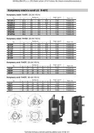
Technical leaflet<strong>Solenoid</strong> <strong>valves</strong> type <strong>EVR</strong> 2 <strong>→</strong> <strong>40</strong> − <strong>NC</strong> / <strong>NO</strong>Design / Function<strong>EVR</strong> 2 (<strong>NC</strong>)<strong>EVR</strong> 10 (<strong>NC</strong>)<strong>EVR</strong> 10 (<strong>NO</strong>)<strong>EVR</strong> 25 (<strong>NC</strong>)<strong>EVR</strong> 32 and <strong>40</strong> (<strong>NC</strong>)4. Coil16. Armature18. Valve plate / Pilot valve plate20. Earth terminal24. Connection for flexible steelhose28. Gasket29. Pilot orifice30. O-ring31. Piston ring36. DIN plug37. DIN socket(to DIN 43650)<strong>40</strong>. Protective cap/Terminal box43. Valve cover44. O-ring45. Valve cover gasket49. Valve body50. Gasket51. Threaded plug53. Manual operation spindle73. Equalization hole74. Main channel75. Pilot channel76. Compression spring80. Diaphragm/Servo piston83. Valve seat84. Main valve plate90. Mounting hole<strong>EVR</strong> solenoid <strong>valves</strong> are designed on two differentprinciples:1. Direct operation2. Servo operation1. Direct operation<strong>EVR</strong> 2 and 3 are direct operated. The <strong>valves</strong> opendirect for full flow when the armature (16) movesup into the magnetic field of the coil.This means that the <strong>valves</strong> operate with a min.differential pressure of 0 bar.The teflon valve plate (18) is fitted direct on thearmature (16).Inlet pressure acts from above on the armatureand the valve plate. Thus, inlet pressure, springforce and the weight of the armature act to closethe valve when the coil is currentless.2. Servo operation<strong>EVR</strong> 6 <strong>→</strong> 22 are servo operated with a "floating"diaphragm (80). The pilot orifice (29) of stainlesssteel is placed in the centre of the diaphragm. Theteflon pilot valve plate (18) is fitted direct to thearmature (16). When the coil is currentless, themain orifice and pilot orifice are closed. The pilotorifice and main orifice are held closed by theweight of the armature, the armature spring forceand the differential pressure between inlet andoutlet sides.When current is applied to the coil the armatureis drawn up into the magnetic field and opens thepilot orifice. This relieves the pressure above thediaphragm, i.e. the space above the diaphragmbecomes connected to the outlet side of thevalve.The differential pressure between inlet andoutlet sides then presses the diaphragm awayfrom the main orifice and opens it for fullflow. Therefore a certain minimum differentialpressure is necessary to open the valve and keepit open. For <strong>EVR</strong> 6 <strong>→</strong> 22 <strong>valves</strong> this differentialpressure is 0.05 bar.When current is switched off, the pilot orificecloses. Via the equalization holes (73) in thediaphragm, the pressure above the diaphragmthen rises to the same value as the inletpressure and the diaphragm closes the mainorifice.<strong>EVR</strong> 25, 32 and <strong>40</strong> are servo operated piston<strong>valves</strong>. The <strong>valves</strong> are closed with currentlesscoil. The servo piston (80) with main valveplate (84) closes against the valve seat (83) bymeans of the differential pressure between inletand outlet side of the valve, the force of thecompression spring (76) and possibly the pistonweight. When current to the coil is switched on,the pilot orifice (29) opens. This relieves thepressure on the piston spring side of thevalve. The differential pressure will then openthe valve. The minimum differential pressureneeded for full opening of the <strong>valves</strong> is 0.2 bar.<strong>EVR</strong> (<strong>NO</strong>) has the opposite function to <strong>EVR</strong> (<strong>NC</strong>),i.e. it is open with de-energised coil.<strong>EVR</strong> (<strong>NO</strong>) is available with servo operation only.© Danfoss A/S (AC-AKC / frz, 05 - 2008 DKRCCPDBB0A302-520H1275 19
Technical leaflet<strong>Solenoid</strong> <strong>valves</strong> type <strong>EVR</strong> 2 <strong>→</strong> <strong>40</strong> − <strong>NC</strong> / <strong>NO</strong>Material specifications<strong>EVR</strong> 2 to 25<strong>Solenoid</strong> <strong>valves</strong>StandardNo. Description <strong>Type</strong> Material Analysis Mat.no. W.no. DIN EN1 Valve body <strong>EVR</strong> 2 to 25 Brass CuZn<strong>40</strong>Pb2 CW617N 2.0<strong>40</strong>2 17672-1 12165<strong>EVR</strong> 2 to 3 Stainless steel X5 CrNi18-10 1.4301 100882 Cover<strong>EVR</strong> 6 to 22 Brass CuZn<strong>40</strong>Pb2 CW617N 2.0<strong>40</strong>2 17672-1 12165<strong>EVR</strong> 25 Cast iron EN-GJS-<strong>40</strong>0-18-LT EN-JS1025 15633 Armature tube <strong>EVR</strong> 2 to 25 Stainless steel X2 CrNi19-11 1.4306 100884 Armature tube nut <strong>EVR</strong> 25 Stainless steel X8 CrNiS 18-9 1.4305 100885 Gasket <strong>EVR</strong> 2 to 25 Rubber Cr6 Gasket <strong>EVR</strong> 25 Al. gasket Al 99.5 3.0255 102107 Solder tube <strong>EVR</strong> 25 Copper SF-Cu CW024A 2.0090 1787 124498 Screws <strong>EVR</strong> 2 to 25 Stainless steel A2-70 35069 Spindle for man. operat. <strong>EVR</strong> 25 Stainless steel X8 CrNiS 18-9 1.4305 1008810 Gasket <strong>EVR</strong> 25 Rubber Cr<strong>EVR</strong> 32 to <strong>40</strong><strong>Solenoid</strong> <strong>valves</strong>StandardNo. Description <strong>Type</strong> Material Analysis Mat.no. W.no. DIN EN1 Valve body <strong>EVR</strong> 32/<strong>40</strong> Cast Iron EN-GJS-<strong>40</strong>0-18-LT EN-JS1025 15632 Cover <strong>EVR</strong> 32/<strong>40</strong> Brass CuZn<strong>40</strong>Pb2 CW617N 2.0<strong>40</strong>2 121653 Armature tube <strong>EVR</strong> 32/<strong>40</strong> Stainless steel X2 CrNi19-11 1.4306 100884 Armature tube nut <strong>EVR</strong> 32/<strong>40</strong> Stainless steel X8 CrNiS 18-9 1.4305 100885 Gasket <strong>EVR</strong> 32/<strong>40</strong> Rubber Cr6 Gasket <strong>EVR</strong> 32/<strong>40</strong> Al. gasket Al 99.5 3.0255 102107 Solder tube <strong>EVR</strong> 32/<strong>40</strong> Copper SF.Cu CW024A 2.0090 1787 124498 Screws <strong>EVR</strong> 32/<strong>40</strong> Stainless steel A2-70 35069 Spindle for. man. operation <strong>EVR</strong> 32/<strong>40</strong> Stainless steel X8 CrNiS 18-9 1.4305 1008820 DKRCCPDBB0A302-520H1275 © Danfoss A/S (AC-AKS / frz),, 05 - 2008
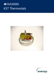
Technical leaflet<strong>Solenoid</strong> <strong>valves</strong> type <strong>EVR</strong> 2 <strong>→</strong> <strong>40</strong> − <strong>NC</strong> / <strong>NO</strong>Dimensions andweights<strong>EVR</strong> (<strong>NC</strong>) 2 <strong>→</strong> 15 and <strong>EVR</strong> 6 <strong>→</strong> 15 (<strong>NO</strong>) , flare connectionWeight of coil10 W: approx. 0.3 kg12 and 20 W: approx. 0.5 kgWith cable connection coilWith DIN plugs coilWith terminal box coil<strong>Type</strong>ConnectionFlareH 1 H 2 H 3 H 4 L L 2 L 3 L 4NVL 5 max.10 W 12/20 Win. mm mm mm mm mm mm mm mm mm mm mm mm mm mm kg<strong>EVR</strong> 2 1 / 4 6 14 73 9 75 45 54 13 75 85 33 68 0.5<strong>EVR</strong> 3<strong>EVR</strong> 6<strong>EVR</strong> 101/ 4 6 14 73 9 75 45 54 13 75 85 33 68 0.53/ 8 10 14 73 9 75 45 54 13 75 85 33 68 0.53/ 8 10 14 78 10 82 45 54 14 75 85 36 68 0.61/ 2 12 14 78 10 88 45 54 14 75 85 36 68 0.61/ 2 12 16 79 11 103 45 54 16 75 85 46 68 0.85/ 8 16 16 79 11 110 45 54 16 75 85 46 68 0.8<strong>EVR</strong> 15 5/ 8 16 19 86 49 131 45 54 24 75 85 56 68 1.0BB 1 max.Weightwithcoil© Danfoss A/S (AC-AKC / frz, 05 - 2008 DKRCCPDBB0A302-520H1275 21
Technical leaflet<strong>Solenoid</strong> <strong>valves</strong> type <strong>EVR</strong> 2 <strong>→</strong> <strong>40</strong> − <strong>NC</strong> / <strong>NO</strong>Dimensions and weights(continued)<strong>EVR</strong> (<strong>NC</strong>) 2 <strong>→</strong> 22 and <strong>EVR</strong> 6 <strong>→</strong> 22 (<strong>NO</strong>), solder connectionWeight of coil10 W: approx. 0.3 kg12 and 20 W: approx. 0.5 kgWith cable connection coilWith DIN plugs coilWith terminal box coil<strong>Type</strong>ConnectionSolderH 1 H 2 H 3 H 4 L L 2 L 3 L 4L 5 max.10 W 12/20 Win. mm mm mm mm mm mm mm mm mm mm mm mm mm kg<strong>EVR</strong> 2 1 / 4 6 14 73 9 102 7 45 54 75 85 33 68 0.5<strong>EVR</strong> 3<strong>EVR</strong> 6<strong>EVR</strong> 10<strong>EVR</strong> 15<strong>EVR</strong> 201/ 4 6 14 73 9 102 7 45 54 75 85 33 68 0.63/ 8 10 14 73 9 117 9 45 54 75 85 33 68 0.63/ 8 10 14 78 10 111 9 45 54 75 85 36 68 0.61/ 2 12 14 78 10 127 10 45 54 75 85 36 68 0.61/ 2 12 16 79 11 127 10 45 54 75 85 46 68 0.75/ 8 16 16 79 11 160 12 45 54 75 85 46 68 0.75/ 8 16 19 86 49 176 12 45 54 75 85 56 68 1.07/ 8 22 19 86 176 17 45 54 75 85 56 68 1.07/ 8 22 20 90 53 191 17 45 54 75 85 72 68 1.51 1 / 8 28 20 90 214 22 45 54 75 85 72 68 1.5<strong>EVR</strong> 22 1 3 / 8 35 20 90 281 25 45 54 75 85 72 68 1.5BB 1 max.Weightwith coil22 DKRCCPDBB0A302-520H1275 © Danfoss A/S (AC-AKS / frz),, 05 - 2008
Technical leaflet<strong>Solenoid</strong> <strong>valves</strong> type <strong>EVR</strong> 2 <strong>→</strong> <strong>40</strong> − <strong>NC</strong> / <strong>NO</strong>Dimensions and weights (continued)<strong>EVR</strong> (<strong>NC</strong>) 25, 32 og <strong>40</strong>, solder connection<strong>EVR</strong> 25<strong>EVR</strong> 32 and <strong>40</strong> terminal box<strong>EVR</strong> 32 and <strong>40</strong><strong>EVR</strong> 25 with terminal box coilWeight of coil10 W: approx. 0.3 kg12 and 20 W: approx. 0.5 kgCoil with cableCoil with DIN plugs<strong>Type</strong><strong>EVR</strong> 25<strong>EVR</strong> 32<strong>EVR</strong> <strong>40</strong>ConnectionSolderH 1 H 2 H 3 H 4 L L 2cableconnectionCoil withL 3Coil withDINconnectionL 4Coil withterminal boxL 5 max.10 W 12/20 Win. mm mm mm mm mm mm mm mm mm mm mm mm mm kg1 1 / 8 28 38 138 72 256 22 45 54 75 85 95 68 3.01 3 / 8 35 38 138 72 281 25 45 54 75 85 95 68 3.31 3 / 8 35 47 111 53 281 25 45 54 75 85 80 68 4.51 5 / 8 42 47 111 53 281 29 45 54 75 85 80 68 4.61 5 / 8 42 47 111 53 281 29 45 54 75 85 80 68 4.62 1 / 8 54 47 111 53 281 34 45 54 75 85 80 68 4.6BB 1 max.Weightwithcoil<strong>EVR</strong> (<strong>NC</strong>) 15 and 20, flange connectionCoil with cableCoil with DIN plugsWeight of coil10 W: approx. 0.3 kg12 and 20 W: approx. 0.5 kgWith terminal box coilWeight of flange setFor <strong>EVR</strong> 15: 0.6 kgFor <strong>EVR</strong> 20: 0.9 kg<strong>Type</strong> H 1 H 2 H 3 H 4 L L 1 L 2 connectionCoil with cableL 3Coil with DINconnectionL 4Coil withterminal boxL 5 max. B B 1 max.10 W 12/20 Wmm mm mm mm mm mm mm mm mm mm mm mm mm kg<strong>EVR</strong> 15 19 86 19 49 125 68 45 54 75 85 80 68 1.2<strong>EVR</strong> 20 20 90 21 53 155 85 45 54 75 85 96 68 1.7Weightwith coilexcl.flanges© Danfoss A/S (AC-AKC / frz, 05 - 2008 DKRCCPDBB0A302-520H1275 23
Technical leaflet<strong>Solenoid</strong> <strong>valves</strong> type <strong>EVR</strong> 2 <strong>→</strong> <strong>40</strong> − <strong>NC</strong> / <strong>NO</strong>24 DKRCCPDBB0A302-520H1275 © Danfoss A/S (AC-AKS / frz),, 05 - 2008