D14922-01 Product description - Luvata heat exchanger HEMT-3
D14922-01 Product description - Luvata heat exchanger HEMT-3
D14922-01 Product description - Luvata heat exchanger HEMT-3

You also want an ePaper? Increase the reach of your titles
YUMPU automatically turns print PDFs into web optimized ePapers that Google loves.
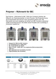
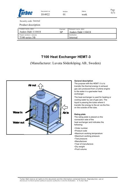
Document no Version Status<strong>D14922</strong> <strong>01</strong> workPage1(7)Security code: Internal<strong>Product</strong> <strong>description</strong>Created (name, date)Project /product / processCheckedReleased (name, date)Anders Dahl 1110418 SP Anders Dahl 110418T100 series 3BDistributionInternalT100 Heat Exchanger <strong>HEMT</strong>-3(Manufacturer: <strong>Luvata</strong> Söderköping AB, Sweden)General <strong>description</strong>The purpose with the <strong>HEMT</strong>-3 is totransfer the thermal energy in exhaustgas (air) produced from a turbine engineto the water in a gas/water <strong>heat</strong><strong>exchanger</strong>.The <strong>heat</strong> <strong>exchanger</strong> is used for <strong>heat</strong>ing orcooling water by use of gas (air). Theliquid is passing the tubes where ittransfer the energy to the air via the finson the outside of the tube.Rating plateThe rating plate is placed on theconnection side of the<strong>heat</strong> <strong>exchanger</strong> and indicates thefollowing:• Order number• <strong>Product</strong> code• Maximum working temperature• Maximum working pressure• Test pressure• Manufacturer• Year of manufacture• Dry weight• Fluid volumeTurbec R&D reserve all rights to this document and the information contained therein. Reproduction, use ordisclosure to third parties without express authority is strictly forbidden. © Turbec R&D
Document no Version Status<strong>D14922</strong> <strong>01</strong> workPage2(7)1 <strong>Product</strong> <strong>description</strong> and safety instructions.........................................................3Handling and care ...................................................................................................... 3Certification................................................................................................................ 3Design......................................................................................................................... 3Heat Exchanger type QMXF:....................................................................................................................... 3Casing: ............................................................................................................................................................. 3Framework: ..................................................................................................................................................... 32 PRODUCT CODE KEY........................................................................................43 Safety .....................................................................................................................44 Installation and maintenance...............................................................................5Transport.................................................................................................................... 5Lifting......................................................................................................................... 5Installation and startup............................................................................................... 5Maintenance ............................................................................................................... 5Cleaning...................................................................................................................... 5Repair work................................................................................................................ 55 Heat Exchanger type QMXF................................................................................6Technical data QMXF ................................................................................................ 6Design......................................................................................................................... 66 Performance ..........................................................................................................7ISO conditions (Ambient temperature 15°C).............................................................. 7Non ISO conditions ..................................................................................................... 7Turbec R&D reserve all rights to this document and the information contained therein. Reproduction, use ordisclosure to third parties without express authority is strictly forbidden. © Turbec R&D
Document no Version Status<strong>D14922</strong> <strong>01</strong> workPage3(7)1 <strong>Product</strong> <strong>description</strong> and safety instructionsHandling and careRead all the maintenance instructions before you begin handling this product. Permit only trainedpersons who have knowledge of the product and appropriate safety precautions to carry out anywork on the cooler.Certification<strong>Luvata</strong> Söderköping AB is certified according to the quality management system ISO90<strong>01</strong>:2008 and according to the environment management system ISO 140<strong>01</strong>:2004.DesignThe <strong>HEMT</strong>-3 consists of three main parts:Heat Exchanger type QMXF:The <strong>heat</strong> <strong>exchanger</strong> is mounted in the casing so it can elongate freely due to thermal expansion. The<strong>heat</strong> <strong>exchanger</strong> is permanently installed in the casing and cannot be removed without major damageto the casing. The <strong>heat</strong> <strong>exchanger</strong> is provided with a temperature sensor for measuring the the wateroutlet temperature. (See page 6 for technical data of QMXF).Casing:The casing works as an exhaust gas channel, which leads the hot exhaust gases from the turbineengine through the <strong>heat</strong> <strong>exchanger</strong>. The casing is provided with an electric controllable by-passvalve, which allows regulation of the outlet water temperature from the <strong>heat</strong> <strong>exchanger</strong> by regulatingthe gas flow through the <strong>heat</strong> <strong>exchanger</strong>. To minimize “thermal leakage” the whole casing isprovided with 30-80mm. thermal insulation on the outside. To measure exhaust gas temperature theunit has been provided with a temperature sensor on the R1/8” connection on the exhaust gas pipe.Framework:The framework holds the casing, thermal insulation and the optional details for the controllablebypass. The framework has been provided with adjustable feet to obtain correct measure from floorto hot air inlet when installing the unit to the turbine application.Turbec R&D reserve all rights to this document and the information contained therein. Reproduction, use ordisclosure to third parties without express authority is strictly forbidden. © Turbec R&D
Document no Version Status<strong>D14922</strong> <strong>01</strong> workPage4(7)2 PRODUCT CODE KEY<strong>HEMT</strong>–3–aa–bb–cc–3<strong>HEMT</strong> = Heat <strong>exchanger</strong> Micro Turbine.3 = Typeaa = <strong>01</strong>. Standard unit, PED 97/23/EC, CE-Marked.bb = <strong>01</strong>. With step loose controllable bypass.cc = <strong>01</strong>. Low flow version, Turbec spec: D1232902. High flow version, Turbec spec: D147433 = Design variable3 Safety• Avoid getting in contact with all of the surfaces on the <strong>HEMT</strong>-3 when the application is inservice or just after because the surfaces can be hot, up to +60°C.• When lifting the unit always follow the instructions, see Lifting page 3. The pipe work shall besupported to prevent any external loads from being transferred to the <strong>heat</strong> <strong>exchanger</strong>.• The <strong>heat</strong> <strong>exchanger</strong> shall only be used in a system, which is secured for the maximumallowable pressure,• see technical data, page 4.• Secure that the <strong>heat</strong> <strong>exchanger</strong> is not used in such a low temperature that risk of freezing isincurred. Even if the turbine application is s topped, cold air may be draft in through the <strong>heat</strong><strong>exchanger</strong>. If the water is freezing in the <strong>heat</strong> <strong>exchanger</strong>, the tubes or bends may burst.• When a <strong>heat</strong> <strong>exchanger</strong> is removed from service the tubes shall after drainage be blownthrough with pressurized air to ensure complete drainage.• A complete draining can also be done by opening all the drain- and vent. nipples, shutting ofthe inlet/outlet water and then blow hot air (exhaust gas from turbine) (>100ºC) through the<strong>heat</strong> <strong>exchanger</strong> so the water within boils and evacuates through the nipples.• If the <strong>heat</strong> <strong>exchanger</strong> is not removed from the installation, the plug in the drain connectionsshall not be mounted because water may leak into the <strong>heat</strong> <strong>exchanger</strong> through leaking shut offvalves.• The pipe work shall be supported to prevent any external loads from being transferred to the<strong>heat</strong> <strong>exchanger</strong>.• If the plugs for the drain/vents are dismounted the old copper gasket shall be replaced withnew ones.Turbec R&D reserve all rights to this document and the information contained therein. Reproduction, use ordisclosure to third parties without express authority is strictly forbidden. © Turbec R&D
Document no Version Status<strong>D14922</strong> <strong>01</strong> workPage5(7)4 Installation and maintenanceTransportCheck that no damage has occurred in connection with transport or unloading. Any transportdamage should be reported immediately to the carrier and to <strong>Luvata</strong> Söderköping AB. Also makenotes on the consignment note.LiftingWhen lifting the unit with chains, always use the lifting lugs. Maximum lifting angle between thechains is 45°. When a forklift is used for lifting, lift with the lower beams on the unit.Observe that the centre of gravity on the unit is very high measured from the floor so when liftingwith forklift secure the unit from tilting.Installation and startupThe pipe work shall be supported to prevent any external loads from being transferred to the <strong>heat</strong><strong>exchanger</strong>. The inlet and outlet connections must be mounted to the pipe work with a soft flangegasket. Don’t use gaskets containing, or are made of metal. Use M16 screws, class 8.8 or higher.When starting the system, the air vent connections must be opened to evacuate air, which hasbeen trapped in the tube circuit. Use the adjustable feet on the framework to get the right measurefrom the floor level to the hot air inlet.Connect the electric couplings for the controllable by-pass motor and the PT-100 temperaturesensor.With the unit a rubber gasket is supplied, this shall be mounted on the unit.MaintenanceThe design is made to prevent maintenance or inspections on a regular basis. When the wholeapplication goes through a major inspection/repair check that the valve in the by-pass channel opensand closes correctly.Always look out for leakage between the inlet/outlet connections the pipe work connections andnipples, if leakage occurs tighten the bolts or replace gaskets if necessary.The unit have been supplied with a hatch allowing access to the <strong>heat</strong> <strong>exchanger</strong> for inspection/cleaning& washing.The unit have also been supplied with a hatch allowing access to the by-pass damper.CleaningOnly use environmentally friendly cleaning agents, which will not damage the <strong>heat</strong> <strong>exchanger</strong>.Repair workParts and material proposed by <strong>Luvata</strong> Söderköping AB must be used in order for the stated guaranteeto apply. The guarantee does not apply to <strong>heat</strong> <strong>exchanger</strong>s that have been damaged through incorrectins tallation, hammering or freezing.Turbec R&D reserve all rights to this document and the information contained therein. Reproduction, use ordisclosure to third parties without express authority is strictly forbidden. © Turbec R&D
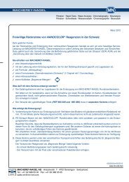
Document no Version Status<strong>D14922</strong> <strong>01</strong> workPage6(7)5 Heat Exchanger type QMXFTechnical data QMXFType: QMXF-2-X-06-06-10-1-10-2Max Working Pressure:Cooling media max/min temp:Exhaust gas max temp:Test Pressure:Calculated lifetime:Conformity:Category (PED):Fluid category (PED):1.6 MPa+150ºC/+0ºC+325ºC3.0 MPa12.000 StartupsPED 97/23/ECIIII (steam)DesignThe <strong>heat</strong> <strong>exchanger</strong> is made of steel tubes, which are mechanical expanded to the AluZinc platedsteel fins. The fins are made as one plate without any slots to avoid clogging by dust or fibres. Themanifold headers, which distribute the liquid in to the tube circuit, is made with a vent. connection onthe top, thread size G1/4”. On the bottom of the outlet header there is a drain connection G1/4”. Theoutlet header has also been provided with a G1/2” connection for a temperature indicator specifiedon drawing R1084095.Tubes:Ø 19.0 x 1.5 mmP235GH, EN 10216-2Headerpipe:Ø 60.3 x 2.9 DN50P235GH, EN 10217-2Aluzinkplated steelfins:Thickness 0.4 mmAluzink AZ 150B500ATurbec R&D reserve all rights to this document and the information contained therein. Reproduction, use ordisclosure to third parties without express authority is strictly forbidden. © Turbec R&D
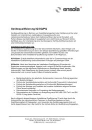
Document no Version Status<strong>D14922</strong> <strong>01</strong> workPage7(7)6 PerformanceISO conditions (Ambient temperature 15°C)Thermal performance v.s. water flowThermalpower output(kW)170(Ambient temp 15°C)Inlet temp. 50°C Inlet temp. 70°CInlet temp. 90°C Inlet temp. 110°C16<strong>01</strong>5<strong>01</strong>4<strong>01</strong>3<strong>01</strong>2<strong>01</strong> 2 3 4 5 6 7 8Water flow (kg/s)Non ISO conditionsThermalpower output(kW)Thermal performance v.s. Ambient temperature(Water flow: 2 kg/s)Thermal power output (kW)17<strong>01</strong>6<strong>01</strong>5<strong>01</strong>4<strong>01</strong>3<strong>01</strong>20-40 -30 -20 -10 0 10 20 30 40 50Ambient temperature (°C)Turbec R&D reserve all rights to this document and the information contained therein. Reproduction, use ordisclosure to third parties without express authority is strictly forbidden. © Turbec R&D