SYNCHRONISED DOME ROTATION - Brayebrook Observatory
SYNCHRONISED DOME ROTATION - Brayebrook Observatory
SYNCHRONISED DOME ROTATION - Brayebrook Observatory

Create successful ePaper yourself
Turn your PDF publications into a flip-book with our unique Google optimized e-Paper software.
<strong>SYNCHRONISED</strong> <strong>DOME</strong> <strong>ROTATION</strong>Anyone who has used an observatory class Equatorial, especially either a German or English Cross Axis Equatorial housed within a dome,cannot fail to have noticed that in order to maintain alignment between the dome slit and the telescope it is necessary to turn the dome at regularintervals. Furthermore the frequency with which the dome slit needs to be advanced very much depends on the telescope’s polar distance. Thetelescope also “looks” through the dome slit obliquely; how obliquely depends on the distance the tube is offset from the polar axis, and howlarge the dome is in relation to the length of the tube, and the distance from the slit to the intersection of the declination and optical axes.When using a large observatory class Equatorial, the observer’s task is made less fraught if dome rotation is motorised and can be controlled viaa handpaddle or computer. When the Equatorial’s drive system is also computer controlled, it helps further if the controller has positional feedback of the dome slit azimuth so that the dome can be turned without observer intervention.There are several ways of synchronising dome rotation and the motion of the Equatorial in hour angle. If the motor is to be actuated via a softwareone needs to derive an algorithm based on trigonometric equations that define the geometrical relationship between the telescope’s declinationand hour angle and the azimuth of the centreline of the dome slit.DETERMINATION of <strong>DOME</strong> AZIMUTHThere are four key elements to this problem. The dome rotation centre, the position of the mounting’s centre of gravity ( cg ) with respect to it, theintersection of the declination axis and the telescope’s optical axis (not necessarily coincident with the tube’s mechanical axis), and a point on theshutter slit defined by the intersection of the optical axis with the slit’s centreline.The solution which follows makes certain assumptions. These are that the mount is either a German or English Cross Axis Equatorial, and that itscg lies on the dome north-south axis. The solution may be extended to cover cases where the cg is offset from the dome centre not only fromthe east-west axis but the north-south axis also.Although derived for either a German or English Cross Axis Equatorial it may be simplified and applied to any other style of equatorial oraltazimuth. When the mount is alt-az and the intersection of the altitude and optical axes lie at the cg, the same rules apply. When the cg lies onthe dome rotation axis the telescope and dome slit azimuth coincide.1
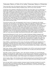
<strong>SYNCHRONISED</strong> <strong>DOME</strong> <strong>ROTATION</strong> - DETERMINATION of <strong>DOME</strong> AZIMUTHStudy the diagram on p2 carefully. Bear in mind it is an isometric projection representing the true 3D geometry. I have set up three rectilinearcoordinate systems. The case considered is of a German or English Cross Axis Equatorial, whose polar axis lies on the north-south meridian, andlies in the same north-south plane as the dome rotation centre. This means the cg also lies in the meridian. (In reality polar misalignment will causeit to be slightly offset, but no matter, it will make next to no difference and can be ignored).The primary coordinate system: X’, Y’, Z’, is that of the telescope, centred on the intersection of the declination and optical axes. I assume thatthese are perpendicular. (In reality there will be a build error, but again, the small error for the purposes of the calculation does not matter).The secondary coordinate system: X, Y, Z, is that of the cg, which if the telescope is accurately balanced about all three axes, i.e. mechanical tubeaxis, declination axis and polar axis, will lie precisely at the intersection of the polar and declination axes. I assume that declination and polar axesare also perpendicular. (In reality there will be a build error, but yet again, the small error for the purposes of the calculation does not matter).The tertiary coordinate system: x,y,z, is that of the dome; z defines the vertical rotation axis, y the meridian axis and x the east-west axis. Theplane defined by x,y lies in the plane of the dome rail.Before going into the details of how the equations are set up, I shall define the terms used in the diagram:Aois dome azimuth measured from north thru’ eastAcg is mount cg azimuth measured from north thru’ eastAzis telescope azimutheis telescope altitude or elevation above the horizonois the dome coordinate system origin in the plane of the dome railpis the point on the slit centreline where the optical axis intersectsp’ is the vertical projection of p onto the x,y planedx,dy,dz, are the coordinates of p with respect to olis the distance from the dome rotation centre to the cgl’ is the distance from the dome rotation centre to mmis the intersection of the declination and optical axesris the distance along the declination axis from the cg to the optical axisr’ is the vertical projection of r onto the x,y planedis the distance from m along the optical axis to pd’ is the vertical projection of d onto the x,y, planeDis the shortest distance from cg to pD’ is the vertical projection of D onto the x,y planeR is the dome radius (assumed centred on o )R’ is the vertical projection of R onto the x,y planeNis the zero azimuth direction of the meridian line coincident with oN’ is the zero azimuth direction of the meridian line coincident with cgN” is the zero azimuth direction of the meridian line coincident with mP* is the north celestial pole3
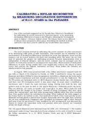
<strong>SYNCHRONISED</strong> <strong>DOME</strong> <strong>ROTATION</strong> - DETERMINATION of <strong>DOME</strong> AZIMUTHReferring to the diagrams on p5:-The ellipse centred on m is a circle whose centre lies in a plane perpendicular to the declination axis.The ellipse centred on cg is a circle whose centre lies in a plane perpendicular to the polar axis.The location of p lies in the plane of the ellipse centred on m and is defined by the declination and hour angle.The location of m lies in the plane of the ellipse centred on cg and is defined by the hour angle measured westwards from the meridian.The distance between the intersection of the declination and optical axes, and the intersection of the optical axis and the centreline of the shutterslit, is defined by the directrix, ‘d’.There are certain terms which can be measured physically. These are:X,Y,Z; R; & r. The elevation of the polar axis is assumed to be the site latitude φ .The sign convention for X,Y,Z and also the primary and tertiary coordinates is:-X (or X’ or x) positive East; negative WestY (or Y’ or y) positive North; negative SouthZ (or Z’ or z) positive above the x,y plane of the dome rail; negative below the x,y plane of the dome rail.Once you have made these measurements, assigned the correct arithmetic signs and noted your site latitude from an ordance survey map youare ready to begin.4
<strong>SYNCHRONISED</strong> <strong>DOME</strong> <strong>ROTATION</strong> - DETERMINATION of <strong>DOME</strong> AZIMUTH5
SETTING UP THE EQUATIONSReferring to VIEW FROM ZENITH. Assume you are looking down on the ellipse centre cg from the zenith. The point of m along the ellipse’scircumference can be used to define Y’ :-hence( X − X' ) 2r 2( rsin H) 2r 2( ) 2= 1( ) 2+ Y − Y'rsin φbut X − X'= rsin H where H is the hour angle( )2+ Y − Y'rsinφfrom which( ) 2 = 1( )( )Y'= Y − rsinφ 1−sin 2 Hhence Y'= Y − rsinφ cos 2 HhenceY'= Y − rsinφ cosH6
SETTING UP THE EQUATIONS (cont.)Referring to VIEW FROM SOUTH. Assume you are looking up the polar axis towards the north celestial pole P*. The point of m along theellipse’s circumference can be used to define Z’ :-hence( X − X' ) 2r 2+( Z' −Z) 2rcosφ( ) 2 =1but X − X' = rsin H where H is the hour angle( rsin H) 2+ Z'−Zr 2 rcosφ( )2from which( ) 2 =1( )( )Z' = Z + r cosφ 1− sin 2 Hhence Z' = Z + r cosφ cos 2 HhenceZ' = Z + r cosφ cos HWe now have all the equations needed to establish the primary coordinates X’,Y’,Z’, from the telescope’s hour angle.when the cg lies on the optical axisX'= X + rsin HY'= Y − rsinφ cosHZ' = Z + r cosφ cos HX'= XY'= YZ' = Zwhen the polar axis lies on the dome north-south centreline X = 07
SETTING UP THE EQUATIONS (cont.)We now need to set up some equations known as equations of state, because they define the relationship between terms we know, and termswe wish to find. These are:R 2 = dx 2 + dy 2 + dz 2R' 2 = dx 2 + dy 2l 2 = X 2 + Y 2 + Z 2l' 2 = X' 2 +Y' 2 +Z' 2D 2 = ( dx − X) 2 + ( dy + Y) 2 + ( dz − Z) 2D' 2 =( dx − X) 2 + ( dy + Y) 2d 2 = ( dx − X' ) 2 + ( dy + Y' ) 2 + ( dz − Z' ) 2( ) 2 + ( dy + Y' ) 2[ ∆ Drd rt∠]d'= dx − X'D 2 = r 2 + d 2Now look at the dashed red line from m, tangent to ellipse cg, perpendicular to dz. The angle between this line, and the line m,p directrix d, is theelevation of the telescope e.The elevation (or altitude) can be calculated from the standard spherical trig formula: cosz = sinφ sin δ + cosφ cosδ cos Hwhere z is zenith distance. Altitude is 90 0 − z .The azimuth of the telescope can be calculated from the standard spherical trig formula: sin z cos A = cosδ sin Hδ & H are declination and hour angle respectively, A is telescope azimuth, Az on the diagram on p2.Hour angle is derived from H = LST −α where LST is local sidereal time & α is right ascension, and must be converted to arc.8
SETTING UP THE EQUATIONS (cont.)9
SETTING UP THE EQUATIONS (cont.)Now consider the diagram on p9. This shows the geometry of the directrix ‘d’ & ‘D’, projected onto the x,y plane, and the elevation of the directrix‘d’ from the x,y plane.from this:but:d'= d cosedx = d'sin Az + X'= d cose.sin Az + X'dy = d'cos Az −Y' = d cose.cos Az −Y'dz = dsin e + Z'R 2 = dx 2 + dy 2 + dz 2= ( d cose.sin Az + X' ) 2 + ( dcose.cos Az − Y' ) 2 + ( d sin e + Z' ) 2= d 2 cos 2 e.sin 2 Az + 2dX'cose.sin Az + X' 2+ d 2 cos 2 e.cos 2 Az − 2dY'cose.cos Az + Y' 2+ d 2 sin 2 e + 2dZ'sin e + Z' 2& rearranging we obtain:R 2 = d 2( cos 2 e.sin 2 Az + cos 2 e.cos 2 Az +sin 2 e)( )+ 2d X'cose.sin Az − Y'cose.cos Az + Z'sin e+ X' 2 +Y' 2 +Z' 2 10
SETTING UP THE EQUATIONS (cont.)which is a quadratic of the form:( cos 2 e.sin 2 Az + cos 2 e.cos 2 Az + sin 2 e)d 2+ 2( X'cose.sin Az − Y'cose.cos Az + Z'sin e)d( ) = 0+ X' 2 +Y' 2 +Z' 2 −R 2but: l' 2 = X' 2 +Y' 2 +Z' 2& simplifying cos 2 e.sin 2 Az + cos 2 e.cos 2 Az + sin 2 esincesin 2 Az =1− cos 2 Azand sin 2 e = 1− cos 2 eby substitution:cos 2 e.sin 2 Az + cos 2 e.cos 2 Az + sin 2 e = cos 2 e 1− cos 2 Az ( ) + cos 2 e.cos 2 Az + 1− cos 2 e ( )and putting:= cos 2 e − cos 2 e.cos 2 Az + cos 2 e.cos 2 Az +1− cos 2 e= 1L = X'cose.sin Az −Y'cose.cos Az + Z'sin eM = l' 2 −R 2d 2 + 2Ld + M = 0from which d = −L ± L 2 − Mbut d is always positive: ∴ d = ( L 2 − M) − L11
SETTING UP THE EQUATIONS (cont.)Once the length of directrix ‘d’ has been determined it becomes possible to derive dx; dy; dz,and hence dome azimuth:Ao = arctan dxdyThere is one caveat in determining Ao, and that is the sign of X’.When the telescope is east of the pier (circle following) X’ is positive.When the telescope is west of the pier (circle preceding) X’ is negative.A meridian reversal will consequently change the sign of X’.<strong>SYNCHRONISED</strong> <strong>DOME</strong> <strong>ROTATION</strong> - RATE of CHANGE of <strong>DOME</strong> SLIT AZIMUTHrate of rotation of dome is derived from:dAodH= −15 ( sinφ − cot z.cos Ao.cosφ )where Ao & H are expressed in arcsecs and seconds of time respectivelyNOTE:0 ≤ A ≤180 o ⇔ 0 ≤ H ≤ 12 h0 ≥ A ≥ −180 o ⇔12 h ≤ 24 h12
<strong>SYNCHRONISED</strong> <strong>DOME</strong> <strong>ROTATION</strong> - USING THE EQUATIONS TO DEVELOPE AN ALGORITHMYour algorithm needs measured constant distances to be input: X; Y; Z; R & r, together with your site latitude, φ ,and a continuous real time or periodic update of Az & e, and H.φ ; r; Y; Z & H are used to calculate X’; Y’; Z’The algorithm must procede as follows:-line operation10 enter φ (constant)2030enter δ & H (H variable with local sidereal time) & convert to e & Azenter r, X, Y, Z, & R40 determine X'= X + rsin H50 determine Y'= Y − rsinφ.cos H60 determine Z' = Z + r cosφ.cosH70 determine l'= X' 2 +Y' 2 +Z' 280 determine coefficient L = X'cose.sin Az − Y'cose.cos Az + Z'sin e90 determine coefficient M = l ' 2 −R 2( ) − L100 determine d = L 2 − M110 determine dx = d cose.sin Az + X'120 determine dy = d cose.cos Az −Y'130 determine dz = d sin e + Z'140 determine Ao = arctan dxdy150 determine dAodH= −15 ( sinφ − cot z.cos Ao.cosφ )13
<strong>SYNCHRONISED</strong> <strong>DOME</strong> <strong>ROTATION</strong>Angles must obey the four quadrant rules:quadrant 1 quadrant 4⎧ ( cosδ.sin H)⎫Az = acos⎨⎬⎩ sin z ⎭ − π 2⎛X'_ east = X + r sin⎜H + 3 ⎝ 2 π ⎞⎟⎠⎛X'_ west = X + rsin H + π ⎞⎜ ⎟⎝ 2⎠Az = 3 2 π + acos ⎧ ( cosδ.sin H)⎫⎨⎬⎩ sin z ⎭⎛X'_ east = X + r sin⎜H + 3 ⎝ 2 π ⎞⎟⎠⎛X'_ west = X + rsin H + π ⎞⎜ ⎟⎝ 2⎠quadrant 2 quadrant 3Az = 3 2 π − acos ⎧ ( cosδ.sin H)⎫⎨⎬⎩ sin z ⎭⎛X'_ east = X + r sin H + π ⎞⎜ ⎟⎝ 2⎠⎛X'_ west = X + rsin⎜H + 3 ⎝ 2 π ⎞⎟⎠Az = 3 2 π − acos ⎧ ( cosδ.sin H)⎫⎨⎬⎩ sin z ⎭⎛X'_ east = X + r sin H + π ⎞⎜ ⎟⎝ 2⎠⎛X'_ west = X + rsin⎜H + 3 ⎝ 2 π ⎞⎟⎠14
<strong>SYNCHRONISED</strong> <strong>DOME</strong> <strong>ROTATION</strong><strong>DOME</strong> DRIVING RATIONALESIt might be reasonably thought that having derived an algorithm defining the azimuth of the dome slit in an absolute relation to telescope’sdeclination and hour angle, and the rate at which the dome needs to be turned so the slit keeps up with the telescope as it tracks an object, that itwould simply be a matter of writing a programme to turn the dome drive motor at the calculated rate. However driving a dome continuously, as faras the ATMer is concerned presents certain problems.If you choose to drive the dome continuously (which for reasons I will explain in the conclusion is not recommended), you will need to run yourprogramme derived from your algorithm in real time, which calls for a real time operating system. The popular IBM clone operating systemWinXP & its predecessors including DOS6.2, & Apple’s Mac OS Classic are not real time or even soft real time OS’s. You will need to port yourprogramme to either a Linux distribution such as RedHat or MacOS X. Either of these operating systems are able to control commandprocessing in real time because of the way they handle interrupt requests to the CPU.You will also need some feedback mechanism to close the drive loop. It is insufficient to put an encoder on the dome gearmotor output spindleand expect dome slit synchronisation to be maintained. Proximity sensors and pickups should be placed around the dome and dome rail toprovide azimuth information at a resolution of at least one third the angular width of the slit.There are also mechanical disadvantages in choosing to drive your dome continuously. The motor will be continuously energized and will run hotand create dome seeing problems. You will have to damp out motor vibration. Also slit azimuth synchronisation may be lost during a meridianreversal (“walking the dog”) and will have to be re-established. However there is a more immediate difficulty, inadequate dynamic range. Forexample, at my site latitude (+52o), the average dome tracking rate is approximaltely 12o per hour, except near the zenith where the rateincreases considerably. Let us assume it is envisaged that either a capacitor start AC induction or shunt wound DC gearmotor is to be selected. Inorder to continuously drive the dome at such a slow speed, the gearhead ratio will need to be enormous. But when we wish to point thetelescope to a different object, we need the dome to rotate much faster than 12o per hour. My dome for instance turns through 360o in 3 minutes,or 2o per second. This is 7200 times faster than the average tracking rate. No AC induction motor or shunt wound DC motor can accommodatesuch a vast dynamic range. There are only three practical alternatives. Either a custom engineered differential or electromagnetic clutch and twomotors, or a DC Torque motor or a DC Servo motor. None of these practical solutions are economic.It is feasible to step turn the dome using software by modifying the algorithm to take into account the difference between the telescope anddome slit azimuth. Suppose for instance the angular width of the slit from the dome centre is 15o, and suppose the slit width is three times thetelescope aperture. The maximum azimuth difference permissible before the slit begins to cut off light to the objective will be 10o. The dome willhave to be turned to an azimuth such that the following side of the slit just clears the objective. The telescope’s azimuth may then advance 10ountil the dome is given a catch-up command. The difficulty lies in calculating the catch-up azimuth angle because it will not be equal to the change intelescope azimuth. If the catch-up azimuth is assumed to be equal to the change in telescope azimuth, synchronisation will inevitably be lost.The alternative software approach is to run the programme at preset intervals, and issue turning commands until synchronisation or apredetermined offset is re-established.15
<strong>DOME</strong> DRIVING RATIONALES (cont.)I have written an AppleWorks v6 and an Xcel2000 spreadsheet which can be downloaded and run on either an AppleMac on MacOS9.1 or anIBM compatible PC on WinME or XP. It is an interesting and illustrative exercise to see how the dome drive rate changes by setting thetelescope’s declination and hour angle such that the telescope is pointing northeast, and then to systematically increase hour angle to simulatetracking an object as it rises, culminates at the zenith and then sets in the northwest.As the telescope is tracked across the zenith, westwards, the dome drive rate steadily increases from approximately 12o per hour to infinity. Atleast it does in theory. In practice, the dome has to be turned through a large angle in a very short time, say 90o in 2 minutes. Producing aworkable software solution to this problem involves knowledge of the maximum dome drive rate and the angular width of the dome slit.Most dome slits do not extend across the entire hemisphere of the dome, but truncate just beyond the zenith. I have written the equations toderive only one value for A 0to reflect this. In theory there are two values, 180o apart.Because dy can equal zero, A 0becomes indeterminate at the East & West Cardinal compass points:fromA 0= arctan dxdywhen dy = 0 A 0= 90 o or 270 o E or W( )no trig solution for A ois possible when dy is zero, because you cannot divide by zero.⎧ cosδ.sin HFurthermore the reduced telescope azimuth angle from Az = arccos⎨⎩ sin z( )has a pair of possible solutions, only one of which is relevant and the equation becomes indeterminate when z = 0 o .The final difficulty you are going to encounter in using software to synchronize dome rotation is during a meridian reversal. Suppose for instancethat the difference in dome slit and telescope azimuth is 10o. When the telescope is reversed across the meridian, dome azimuth must changeby twice this difference, or 20o. Also do not forget that the sign of X’ will change. You will have to add code to account for these changes.⎫⎬⎭16
<strong>DOME</strong> DRIVING RATIONALES (cont.)SUMMARYWhilst it is possible to synchronize dome rotation and dome slit azimuth with telescope declination and hour angle using a software solution thereare inherant difficulties in doing so.These are:i) When the dome is driven continuously the motor will need a huge dynamic range, or two motors must be used.ii) Difficulties in dealing with heat.iii) Difficulties in damping vibration.iv) Additional sub-routines needed to deal with: indeterminate conditionsmeridian reversalszenith passagequadrant rulesThat is why I recommend designing a dome rotation system that does not wholely rely on a software, and one that advances the dome in steps.COMMERCIAL SOLUTIONSVarious dome manufacturers offer domes with motorised shutter and rotation options, for example see .None so far as I am aware offer hardware dome synchronisation. There are several observatory control software suites that include domesynchronisation, although it is embedded in either complete automation or remote operation.The precursor to these total software solutions was OCAAS, “<strong>Observatory</strong> Control and Astronomical Analysis System” written by ElwoodDowney at the Clear Sky Institute .The copywrite and source code was sold to Torus Technologies in 1999, who in turn sold it to Optical Mechanics in 2001 who renamed it TALON .It has been developed into a complete observatory, telescope and ccd camera control and data processing suite, even including PatrickWallace’s telescope pointing analysis programme, TPoint .DFM Engineering offer total solutions to telescope and observatory control which includes domesynchronisation, as do Astronomical Consultants & Equipment ,Optical Guidance Systems and Astralnomicon <strong>Observatory</strong> Systems .However these companies do not offer economical single end user site licences for their software making them unattractive for the lone ATMer.Their softwares are however ported to professional Unix platforms with the distinct advantage brought by a soft real time operating system. It isof course feasible to install Linux on either a PC or an AppleMac, and MacOSX is a Unix based OS in any case.17
<strong>DOME</strong> DRIVING RATIONALES (cont.)COMMERCIAL SOLUTIONS (cont.)The following are PC software solutions:-Technical Innovations' Digital Dome Works a PC automation system supplied with ROBO-<strong>DOME</strong>.Software Bisque's AutomaDome a PC application that integrates withTheSky Astronomy Sotware to control robotic domes.AstroDigitals’ Meridian Dome Automation System supplied with ObservaDome, orMeridian Controls Corporation intended for use with a closed loop DC servo azimuth drive.18
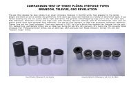
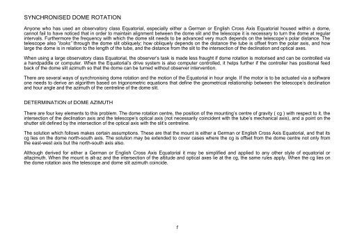
<strong>DOME</strong> DRIVING RATIONALES (cont.)ATM SOLUTIONSBrent Boshart has written a PC shareware pcdome.exe for the now defunct Boydcommercial domed observatory. See for an example of its use by ThomasWichmann. Brent Boshart’s shareware programme has unfortunately been pulled because Boyd Observatories Inc. has folded. However its usein the system implemented by Thomas Wichmann is ingenious as he describes:-.The basic idea is to incorporate a microcontroller into the controller box. The microcontroller "speaks" via serial lines to both the mount and the motor controllerboard. In the "regular" mode, the system simply permits to manually move the dome in clockwise or counterclockwise direction, and, of course, to stop its motion.In the "slave" mode, the dome is linked to the mount so that the dome's slit is always pointing in the direction of the telescope. For this, the mount is polled forazimuth (in the case of fork-mounted scopes), or azimuth and altitude (in the case of GEMs or other mounts); the information is used to calculate the targetdome azimuth, and the dome is moved to that target azimuth. The target calculation and movement is updated regularly so that the dome keeps up with thetelescope. For fork-mounted telescopes which are positioned so that the declination axis is the center of the dome (which means having an eccentric pier!), thedome azimuth always conincides with the scope azimuth. In GEMs, the translation between scope pointing and dome azimuth is not as simple, because therelationship between scope azimuth and dome azimuth varies with the scope altitude. The math behind this is complicated, and I finally settled (with the help ofBrent Boshart) on a more empiric approach, i.e., the program uses an input table that links scope pointing information to a certain dome azimuth.This image shows the (empiric) relationship between azimuth and altitude readoutfrom my mount and the dome azimuth required to place the dome shutter in line withthe optic axis.Linking the dome to the scope could be accomplished most elegantly through directcalculation of the dome azimuth from the telescope pointing information. This iscomplicated math. I have tried to develop the respective algorithms for a while, andhave, thus far, failed to come up with a viable algorithm for this - the problem is not somuch the translation of the hour angle/declination into dome azimuth, but the factthat the mount is not exactly in the center of the dome (see image above). Asmentioned above, Brent Boshart came up with an alternative approach that actuallyworks well, and is based on a lookup table. Scope azimuth/altitude and East/Westinformation are then used to find the two closest dome azimuth values in the lookuptable. The actual target azimuth is then determined via a simple interpolation routine.The BX-24 microcontroller is able to run through this calculation intensive routineabout once every second, so that reasonable 'slaving' accuracy can be achieved.Each iteration of this routine ends in transformation of the dome azimuth (in degrees)into the equivalent encoder counts, and a GoToTarget step, during which the IPMcard receives the current target, and initiates driving the motor towards that target.This approach, although telescope / dome specific, circumvents theprogramming complications referred to on p17.19
<strong>DOME</strong> DRIVING RATIONALES (cont.)ATM SOLUTIONS (cont.)Jack Patterson, Nubbin Ridge <strong>Observatory</strong>, Hot Springs, Arkansas, USA, has written a PC freeware called JPDome,see HARDWARE SOLUTIONSThere are two hardware solutions to this problem, both of which are affordable, completely reliable under all possible circumstances, and moreimportantly, simple to set-up.The first assumes you have no computer control. All that is needed is a coil and oscillator fitted to the mouth of the telescope tube, and a bell wirecircuit to both sides of the slit, and connected to an op-amp and Schmidt trigger. The coil and oscillator sets up a toroidal electromagnetic fieldaround the end of the tube. As the tube moves towards the preceding side of the slit, it induces a weak current in the bell wire. This current isamplified and at a predetermined level causes the trigger cct. to close the preceding dome drive relay. This in turn causes the dome to turn and asthe separation of the bell wire and the field grows again, the induced current collapses, the trigger flips back and causes the relay to open and thedome to stop turning.If the dome motor and drive speed are designed to turn the dome at an angular rate which matches the slew rate of the telescope then thissystem will also maintain synchronisation when the telescope is either repointed eastwards or westwards, slewed across the zenith or reversedacross the meridian.The alternative hardware solution assumes you have a computer controlled telescope drive that enables data inputs for dome azimuth andshutter open / closed conditions, such as the AWR Intelligent Drive System .All you need are proximity sensors to provide this information. I strongly suggest you use Hall effect Reed switches for this purpose. Directionaloptical / IR or Ferro-magnetic proximity sensors are very expensive in comparison.A pair of Reed proximity switches @ 22o.5 and 24 magnetic pickups spaced at 15o intervals around the dome rail will provide 7o.5 resolution.Add a third Reed switch @ 3o.75 from the second, and the resolution will be increased to 3o.75. The azimuth information from the dome is fed tothe controller and when the telescope azimuth exceeds the dome azimuth by the resolution limit the controller initiates a stepwise dome rotationuntil it receives a signal from the next pickup.Information of shutter open or closed can also be provided to the controller via proximity switches and sensors at the limits of travel. Contact me ifyou want more specific design and construction details. I can provide circuit diagrams and component lists at a modest cost, tailored to yourspecific needs.20