MAN-TC-145-R03
MAN-TC-145-R03
MAN-TC-145-R03

You also want an ePaper? Increase the reach of your titles
YUMPU automatically turns print PDFs into web optimized ePapers that Google loves.
Hydraulic Tubing Drain<strong>TC</strong>-<strong>145</strong>-2375-000<strong>TC</strong>-<strong>145</strong>-2875-000<strong>MAN</strong>-<strong>TC</strong>-<strong>145</strong> (<strong>R03</strong>)Owen Oil Tools5405 39139 Hwy 2ARed Deer County Alberta Canada T4S 2B3Phone: 1-403-340-1017Fax: 1-403-340-1415Toll Free: 1-888-345-1017Warning: Use of Owen equipment contrary to manufacturer’s specifications or operating instructions may result in property damage, serious injury or fatality. If you are nottrained in the handling and use of explosive devices, do not attempt to use or assemble any Owen perforating systems or Owen firing devices.Owen Oil Tools pre-assembles its tools as per the field operating manual. It is the responsibility of the purchaser to insure that this tool is assembled as required, prior to use.This technology is regulated by and, if exported, was exported from the United States in accordance with the Export Administration Regulations (EAR). Diversion contrary to USDepartment of Commerce. Consult the BIS, the EAR and/or Owen Compliance Services, Inc. to determine licensing requirements for export or re-export of this technology.This document contains Confidential information of Owen Oil Tools LP (Owen) and is furnished to the customer for information purposes only. This document must not be reproducedin any way whatsoever, in part or in whole, or distributed outside the customer organization, without first obtaining the express written authorization of Owen. This documentis the property of Owen and returnable upon request by Owen.©2009 Owen Oil Tools
Hydraulic Tubing Drain<strong>MAN</strong>-<strong>TC</strong>-<strong>145</strong>Owen Oil ToolsBlank PageRevised 07/2012<strong>MAN</strong>-<strong>TC</strong>-<strong>145</strong>.2
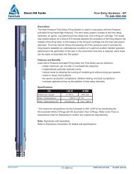
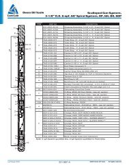
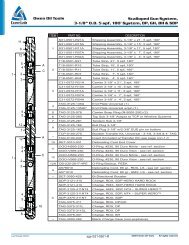
Hydraulic Tubing DrainOwen Oil Tools<strong>MAN</strong>-<strong>TC</strong>-<strong>145</strong>DescriptionThe Hydraulic Tubing Drain may be used in conjunction with Hydraulic ActuationEquipment and serves as a means of draining tubing fluids to the wellbore aftersetting tools or firing perforating guns. The Hydraulic Tubing Drain is operated bythe differential pressure between the hydrostatic pressure in the annulus, and thecombination of hydrostatic and applied pressure in the tubing.The Hydraulic Tubing Drain features an internal Sliding Sleeve which seals againstthe drain ports, isolating tubing pressure from the annulus. The sleeve is held inplace with Shear Screws. By applying a predetermined pressure to the inside of thetubing, the screws shear and the sleeve shifts. Once shifted, the sleevepermanently opens the ports which provides a flow area equal to that of the tubingID.The tubing drain is used with any tubing conveyed application that requires drainageor that is activated by differential pressure, including Hydraulic Firing Heads.Example applications are:• Horizontal and Vertical Hydraulic Tool Actuation: the tubing drain is usedhere to drain fluid from the tubing after a particular hydraulic tool has beenactivated• Horizontal and Vertical Perforating: the tubing drain is used to drain fluid fromthe tubing after the guns have been fired• Extreme Overbalanced Perforating: the tubing drain is designed to openprior to firing the guns so that tubing fluids are forced against the casing underextreme pressureFeatures and Benefits• Internal sleeve design decreases the risk of premature sleeve shift• Sliding internal sleeve will shift in any hole deviation• The sleeve locks in the open position upon shifting to guarantee continuous flowthrough the tubing drain ports• Large flow area permits temporary use as a perforated nipple for productionSpecifications2-3/8 in (60.3 mm)2-7/8 in (73.0 mm)Maximum OD 3.062 in 77.8 mm 3.668 in 93.2 mmMinimum ID 1.750 in 44.5 mm 2.250 in 57.2 mmFlow Area 2 3.316 in 2 2140 mm 2 4.690 in 2 3026 mm 2Maximum Pressure 11,900 psi 82.1MPa 11,100 psi 76.5 MPaMax Temp 1250 o F (121 o C)ConnectionsProduct NumberRedress Kit2-3/8 in (60.3 mm)EU Box X Pin<strong>TC</strong>-<strong>145</strong>-2375-000<strong>TC</strong>-<strong>145</strong>-2375-0992-7/8 in (73.0 mm)EU Box X Pin<strong>TC</strong>-<strong>145</strong>-2875-000<strong>TC</strong>-<strong>145</strong>-2875-0991The maximum temperature can be increased to 450 o F (230 o C) by substitutingthe 90 durometer Nitrile O-rings with 90 durometer Viton O-rings2 Greater flow area than the tubing bore<strong>MAN</strong>-<strong>TC</strong>-<strong>145</strong>.3Revised 07/2012
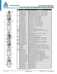
Hydraulic Tubing Drain<strong>MAN</strong>-<strong>TC</strong>-<strong>145</strong>Owen Oil ToolsItem Part Number Qty Description-- <strong>TC</strong>-<strong>145</strong>-2375-000 -- Hydraulic Tubing Drain 2-3/8" EU1 <strong>TC</strong>-<strong>145</strong>-0000-000 1 Top Sub 2-3/8" EU2 <strong>TC</strong>-<strong>145</strong>-0001-000 1 Body3 <strong>TC</strong>-<strong>145</strong>-0002-000 1 Sleeve4 <strong>TC</strong>-<strong>145</strong>-0004-000 1 Snap Ring5 <strong>TC</strong>-<strong>145</strong>-0003-000 1 Bottom Sub 2-3/8" EU6 SF-050-025C-038B 10 Shear Screw 1/4-20 UNC x 3/8 Brass7 MI-305-2375-000 1 Seal Ring 2-7/8" EU8 OOO-N569-143 4 O-Ring 90 Durometer Nitrile9 OOO-N569-137 2 O-Ring 90 Durometer NitrileItem Part Number Qty Description-- <strong>TC</strong>-<strong>145</strong>-2375-099 --Redress Kit Hydraulic Tubing Drain2-3/8" EU6 SF-050-025C-038B 10 Shear Screw 1/4-20 UNC x 3/8 Brass7 MI-305-2875-000 1 Seal Ring 2-7/8" EU8 OOO-N569-143 4 O-Ring 90 Durometer Nitrile9 OOO-N569-137 2 O-Ring 90 Durometer NitrileHydraulic Data 2-3/8Piston Area1.308 sq.in. (843.9 sq.mm)Shear Screw Strength 1 screw min - 1,415 lb. (629.4 daN) + 15%Opening Pressure 1,082 psi/screw (7460 kPa/screw)Max Opening Pressure 10,890 psi (75090 kPa) @ 10 screwsItem Part Number Qty Description-- <strong>TC</strong>-<strong>145</strong>-2875-000 -- 2-7/8" EU Hydraulic Tubing Drain1 <strong>TC</strong>-<strong>145</strong>-0005-000 1 Top Sub 2-7/8" EU2 <strong>TC</strong>-<strong>145</strong>-0006-000 1 Body3 <strong>TC</strong>-<strong>145</strong>-0007-000 1 Sleeve4 <strong>TC</strong>-<strong>145</strong>-0009-000 1 Snap Ring5 <strong>TC</strong>-<strong>145</strong>-0008-000 1 Bottom Sub 2-7/8" EU6 SF-050-025C-038B 10 Shear Screw 1/4-20 UNC x 3/8 Brass7 MI-305-2875-000 1 Seal Ring 2-7/8" EU8 OOO-N569-150 4 O-Ring 90 Durometer Nitrile9 OOO-N569-146 2 O-Ring 90 Durometer NitrileItem Part Number Qty Description-- <strong>TC</strong>-<strong>145</strong>-2875-099 --Redress Kit Hydraulic Tubing Drain2-7/8" EU0 MI-305-2875-000 1 2-7/8" EU Thread API Seal Ring6 SF-050-025C-038B 10 Shear Screw 1/4-20 UNC x 3/8 Brass8 OOO-N569-150 4 O-Ring 90 Durometer Nitrile9 OOO-N569-146 2 O-Ring 90 Durometer NitrileHydraulic Data 2-7/8Piston Area1.526 sq.in. (985 sq.mm)Shear Screw Strength 1,415 lb. (629.4 daN) + 15%Opening Pressure 927 psi/screw (6391 kPa/screw)Max Opening Pressure 9,270 psi (63914 kPa) @ 10 screwsRevised 07/2012<strong>MAN</strong>-<strong>TC</strong>-<strong>145</strong>.4
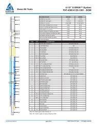
Hydraulic Tubing DrainOwen Oil Tools<strong>MAN</strong>-<strong>TC</strong>-<strong>145</strong>Assembly and DisassemblyRefer to Figure 1 Explosion ViewStep 1Thread the Bottom Sub (Item 5) into the Body (Item2) and torqueStep 2Slide the Snap Ring (Item 4) over the Sleeve (Item 3)until it snaps into its groove as show in Figure 1.Lightly grease the O-rings (Items 8 and 9) and installthem onto the Sleeve (Item 3). Slide the Sleeve(Item 3), small end first, into the Body (Item 2). Slidethe Sleeve into the Body far enough to let the threadof the Top Sub (Item 1) engage the Body thread.Step 3Lightly grease O-rings (Item 8) and install onto theTop Sub (Item 1). Install the Seal Ring (Item 7) intothe EU thread of the Top Sub. Now thread the TopSub (Item 1) into the Body (Item 2).Note: as you shoulder the Top Sub to the Body, theshear holes on the body should be aligned with thegroove in the Sleeve (Item 3). Now torque the TopSub.Step 4Thread the Shear Screws (Item 6) into the shearholes of the Body (Item 2). The number of shearscrews will vary with each well condition.<strong>MAN</strong>-<strong>TC</strong>-<strong>145</strong>.5Revised 07/2012