02 . 01 D-Sub â E D-Sub â Standard subminiature D connectors ...
02 . 01 D-Sub â E D-Sub â Standard subminiature D connectors ...
02 . 01 D-Sub â E D-Sub â Standard subminiature D connectors ...
- No tags were found...

Create successful ePaper yourself
Turn your PDF publications into a flip-book with our unique Google optimized e-Paper software.
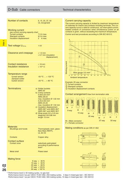
D-<strong>Sub</strong> Cable <strong>connectors</strong>Technical characteristicsNumber of contacts 9, 15, 25, 37, 50UL recognizedWorking currentsee current carrying capacity chartTurned contacts7.5 A max.Stamped contacts6.5 A max.Insulation displacement 2.0 A max.Current carrying capacityThe current carrying capacity is limited by maximum temperatureof materials for inserts and contacts including terminals. The currentcapacity-curve is valid for continuous, not interrupted currentloadedcontacts of <strong>connectors</strong> when simultaneous power on allcontacts is given, without exceeding the maximum temperature.Control and test procedures according to DIN IEC 60 512.D-<strong>Sub</strong> - STest voltage U r.m.s.1 kVClearance and creepage≥ 1.0 mm≥ 0.7 mm (insulationdisplacement)Contact resistanceInsulation resistanceTemperature rangeturned versionstamped solderbucket versionTerminationsMaterialsMouldings and hoodsContactsContact surfaceContact zoneMetal shell≤ 10 mΩ≥ 10 10 Ω-55 O C … + 125 O C-25 O C … + 85 O Ca) Solder bucketsAWG 20b) Crimp contacts0.09-0.25 mm²AWG 28-24max. insulation Ø 1.<strong>02</strong> mm0.25-0.56 mm²AWG 24-20max. insulation Ø 1.52 mmc) Insulation displacementAWG 28/7 and AWG 26/7AWG 28/1 and AWG 30/1d) Wrap posts 0.6 x 0.6 mmdiagonal 0.8-0.86 mmlength 13 mmThermoplastic resin, glassfibrefilled (PBTP),UL 94-V0Copper alloyselectively gold-platedaccording to performancelevel 1)Plated steelWorking currentContact arrangement View from termination sideM F9 wayWire gauge: 0.5 mm 2Ambient temperatureExample: 25 way connector➀ Turned contacts➁ Stamped contacts➂ Insulation displacement contactsM F15 wayM = Male connectorF = Female connectorM F25 wayMating conditions as per DIN 41 652M F M F37 way 50 way<strong>02</strong> .26Mating force9 way ≤ 30 N15 way ≤ 50 N25 way ≤ 83 N37 way ≤ 123 N50 way ≤ 167 N1)Performance level 3, 50 mating cycles, no gas testPerformance level 2 as per CECC 75 3<strong>01</strong>-8<strong>02</strong>, 250 mating cycles, 4 days 4 mixed gas test – IEC 60 512Performance level 1 as per CECC 75 3<strong>01</strong>-8<strong>02</strong>, 500 mating cycles, 10 days 4 mixed gas test – IEC 60 512