02 . 01 D-Sub â E D-Sub â Standard subminiature D connectors ...
02 . 01 D-Sub â E D-Sub â Standard subminiature D connectors ...
02 . 01 D-Sub â E D-Sub â Standard subminiature D connectors ...
- No tags were found...

Create successful ePaper yourself
Turn your PDF publications into a flip-book with our unique Google optimized e-Paper software.
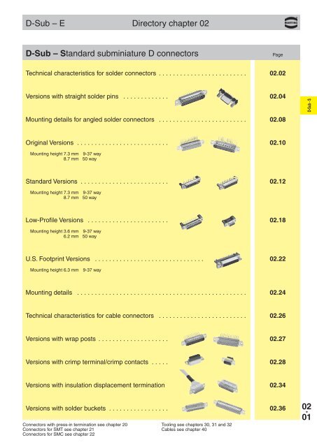
D-<strong>Sub</strong> DIN 41 652 · CECC 75 3<strong>01</strong>-8<strong>02</strong> · IEC 60 807Number of contacts9--50D-<strong>Sub</strong> - STurned solder pins, straightNo. ofIdentification contacts Part No.Performance levelsExplanations see page <strong>02</strong>.<strong>02</strong>Other performance levels on requestMale connectormetal shell with dimplesþPerformance level3Performance level29 09 67 009 5654 09 67 009 565515 09 67 <strong>01</strong>5 5654 09 67 <strong>01</strong>5 565525 09 67 <strong>02</strong>5 5654 09 67 <strong>02</strong>5 565537 09 67 037 5654 09 67 037 56555<strong>01</strong>)09 67 050 5654 1) 1)09 67 050 5655 1)Female connectormetal shell9 09 67 009 4754 09 67 009 475515 09 67 <strong>01</strong>5 4754 09 67 <strong>01</strong>5 475525 09 67 <strong>02</strong>5 4754 09 67 <strong>02</strong>5 475537 09 67 037 4754 09 67 037 47555<strong>01</strong>)09 67 050 4754 1) 1)09 67 050 4755 1)Male connectorNo. 1contact9-37 50Mating face acc. to: DIN 41 652CECC 75 3<strong>01</strong>-8<strong>02</strong> · IEC 60 807PCBPillarFemale connectorMating face acc. to: DIN 41 652CECC 75 3<strong>01</strong>-8<strong>02</strong> · IEC 60 807No. 1contactBoard drillingsPCBa b ± 0.1 c g h9 30.9 25.0 12.5 4 x 2.74 = 10.96 3 x 2.74 = 8.2215 39.2 33.3 12.5 7 x 2.74 = 19.18 6 x 2.74 = 16.4425 53.1 47.0 12.5 12 x 2.76 = 33.12 11 x 2.76 = 30.3637 69.4 63.5 12.5 18 x 2.76 = 49.68 17 x 2.76 = 46.9250 67.0 61.1 15.4 16 x 2.76 = 44.16 15 x 2.76 = 41.40<strong>02</strong> .041)Not normally kept in stockNo. 1contactPillarDimensions in mmMating conditions see page <strong>02</strong>.<strong>02</strong>
D-<strong>Sub</strong> - SD-<strong>Sub</strong> DIN 41 652 · CECC 75 3<strong>01</strong>-8<strong>02</strong> · IEC 60 807Number of contacts9--50Turned solder pins, straight without grounding-pinsNo. ofIdentification contacts Part No.Performance levelsExplanations see page <strong>02</strong>.<strong>02</strong>Other performance levels on requestMale connectormetal shell with dimplesþPerformance level3Performance level2availableon request9 09 66 121 770 . 09 66 121 670 .15 09 66 221 770 . 09 66 221 670 .25 09 66 321 770 . 09 66 321 670 .37 09 66 421 770 . 09 66 421 670 .50 09 66 521 770 . 09 66 521 670 .Please insert digit forflange thread or fitted M3 þ 1female screw locks 4-40 UNC þ 2fitted screw locks 4-40 UNC þ 3Male connectorNo. 1 contact9-37 50Mating face acc. to: DIN 41 652CECC 75 3<strong>01</strong>-8<strong>02</strong> · IEC 60 807XBoard drillingsNo. 1 contactDimplesa b ± 0.1 c g h9 30.9 25.0 12.9 4 x 2.74 = 10.96 3 x 2.74 = 8.2215 39.2 33.3 12.9 7 x 2.74 = 19.18 6 x 2.74 = 16.4425 53.1 47.0 12.9 12 x 2.76 = 33.12 11 x 2.76 = 30.3637 69.4 63.5 12.9 18 x 2.76 = 49.68 17 x 2.76 = 46.9250 67.0 61.1 15.7 16 x 2.76 = 44.16 15 x 2.76 = 41.40M3 or4-40 UNCfitted screw locks4-40 UNCDimensions in mmMating conditions see page <strong>02</strong>.<strong>02</strong><strong>02</strong> .05
D-<strong>Sub</strong> DIN 41 652 · CECC 75 3<strong>01</strong>-8<strong>02</strong> · IEC 60 807Number of contacts9--37D-<strong>Sub</strong> - SStamped solder pins, straight with/without grounding board locksNo. ofIdentification contacts Part No.Performance levelsExplanations see page <strong>02</strong>.<strong>02</strong>Other performance levels on requestMale connectormetal shell with dimplesþPerformance level3Performance level2Without grounding board locks9 09 65 121 770 . 09 65 121 670 .15 09 65 221 770 . 09 65 221 670 .25 09 65 321 770 . 09 65 321 670 .37 09 65 421 770 . 09 65 421 670 .With grounding board locks9 09 65 161 771 . 09 65 161 671 .15 09 65 261 771 . 09 65 261 671 .25 09 65 361 771 . 09 65 361 671 .37 09 65 461 771 . 09 65 461 671 .Female connectormetal shellWithout grounding board locks9 09 66 111 750 . 09 66 111 650 .15 09 66 211 750 . 09 66 211 650 .25 09 66 311 750 . 09 66 311 650 .37 09 66 411 750 . 09 66 411 650 .50 09 66 511 750 . 09 66 511 650 .With grounding board locks9 09 66 151 751 . 09 66 151 651 .15 09 66 251 751 . 09 66 251 651 .25 09 66 351 751 . 09 66 351 651 .37 09 66 451 751 . 09 66 451 651 .<strong>02</strong> .06Please insert digit for flange threador fitted female screw locksM3 þ 14-40 UNC þ 2fitted screw locks 4-40 UNC þ 3 1)1)Fitted screw locks 4-40 UNC not normally kept in stock for performance level 3Connector dimensions see page <strong>02</strong>.07. Mating conditions see page <strong>02</strong>.<strong>02</strong>.
D-<strong>Sub</strong> DIN 41 652 · CECC 75 3<strong>01</strong>-8<strong>02</strong> · IEC 60 807Number of contacts9--37Stamped solder pins, straight with/without grounding board locksIdentification Drawing Dimensions in mmMale connector9 – 37 contactsNo. 1contactMating face acc. to: DIN 41 652 · CECC 75 3<strong>01</strong>-8<strong>02</strong>IEC 60 807D-<strong>Sub</strong> - SNut threadFemale connector9 – 37 contactsMating face acc. to: DIN 41 652 · CECC 75 3<strong>01</strong>-8<strong>02</strong> · IEC 60 807No. 1 contactNut threada b ± 0.1 c g h9 30.9 25.0 12.5 4 x 2.74 = 10.96 3 x 2.74 = 8.2215 39.2 33.3 12.5 7 x 2.74 = 19.18 6 x 2.74 = 16.4425 53.1 47.0 12.5 12 x 2.76 = 33.12 11 x 2.76 = 30.3637 69.4 63.5 12.5 18 x 2.76 = 49.68 17 x 2.76 = 46.92Board drillings9 – 37 contacts<strong>02</strong> .07
D-<strong>Sub</strong> - SD-<strong>Sub</strong>Front panel width3 TE3 x 5.08 mmMounting details – angled solder pinspages <strong>02</strong>.18 – <strong>02</strong>.21Low-Profile Versions9-37 wayFront panel width4 TE4 x 5.08 mmpages <strong>02</strong>.12 – <strong>02</strong>.17<strong>Standard</strong> Versionspages <strong>02</strong>.22 – <strong>02</strong>.23U.S. Footprint VersionsOriginal Versionspages <strong>02</strong>.10 – <strong>02</strong>.119-37 way 9-37 way 9-37 way50 wayFront panel width5 TE5 x 5.08 mm50 way50 wayMetal shellmating faceMetal shellfront and rear<strong>02</strong> .08Fixed contactsIntegrated mounting bracketFloating contacts1 piece plastic mountingbracket or 2 piecemetal or plastic brackets
D-<strong>Sub</strong>AdvantagesAll-round protective metal shell● Polarisation● Contact protection● Plated shell● Male connector withdimplesPlated terminationsfor increasedsolderabilityGrounding contactriveted tometal shellIntegrated plastic mounting bracketMounting details – angled solder pinsContact surface finish to differentperformance levelsPanelDifferent metal threads possiblein flange area● M3● 4-40 UNC● fitted female screw locks 4-40 UNC● max. torque ≤ 0.8 NmD-<strong>Sub</strong> - SMounting bracketMounting bracketwith snap-in-clips and grounding pinMounting heightLow-Profile VersionsThe reduced mounting height of these <strong>connectors</strong> allowthem to be used on the same PCB as DIN 41 6129-37 way <strong>connectors</strong> with 3.6 mm mounting height can befitted to front panels of 3 TE (15.24 mm) width.Mounting height 3.6 mmtypes with no loss of packaging density when cardframes to DIN 41 494 are used.50 way <strong>connectors</strong> with 6.2 mm mounting height can befitted to front panels of 4 TE (20.32 mm) width.Mounting height 6.2 mmPCBPCBPanel3 TE 3 x 5.08 mm = 15.24 mm<strong>Standard</strong> VersionsDIN 41 612Original VersionsPanel4 TE 4 x 5.08 mm = 20.32 mmUS FootprintDIN 41 6129-37 way <strong>connectors</strong> with 7.3 mm mounting height can befitted to front panels of 4 TE (20.32 mm) width.Mounting height 7.3 mm(6.3 US Footprint)50 way <strong>connectors</strong> with 8.7 mm mounting height can befitted to front panels of 5 TE (25.4 mm) width.Mounting height 8.7 mmPCBPCBPanel4 TE 4 x 5.08 mm = 20.32 mmDIN 41 612Panel5 TE 5 x 5.08 mm = 25.4 mmDIN 41 612<strong>02</strong> .09
D-<strong>Sub</strong> - SD-<strong>Sub</strong> DIN 41 652 · CECC 75 3<strong>01</strong>-8<strong>02</strong> · IEC 60 807Number of contacts9--50Original VersionsTurned solder pins, angled without fixing bracketNo. ofIdentification contacts Part No.Performance levelsExplanations see page <strong>02</strong>.<strong>02</strong>Other performance levels on requestMale connectormetal shell with dimplesþPerformance level3Performance level22.84 mm pitch 2.84 mm pitch9 09 67 009 5663 09 67 009 566415 09 67 <strong>01</strong>5 5663 09 67 <strong>01</strong>5 566425 09 67 <strong>02</strong>5 5663 09 67 <strong>02</strong>5 566437 09 67 037 5663 09 67 037 566450 09 67 050 56632)09 67 050 5664 2)2.54 mm pitch 2.54 mm pitch92)09 67 009 5657 2) 2)09 67 009 5658 2)152)09 67 <strong>01</strong>5 5657 2) 2)09 67 <strong>01</strong>5 5658 2)252)09 67 <strong>02</strong>5 5657 2) 2)09 67 <strong>02</strong>5 5658 2)372)09 67 037 5657 2) 2)09 67 037 5658 2)5<strong>02</strong>)09 67 050 5657 2) 2)09 67 050 5658 2)Female connectormetal shell2.84 mm pitch 2.84 mm pitch9 09 67 009 4763 09 67 009 476415 09 67 <strong>01</strong>5 4763 09 67 <strong>01</strong>5 476425 09 67 <strong>02</strong>5 4763 09 67 <strong>02</strong>5 476437 09 67 037 4763 09 67 037 476450 09 67 050 4763 * ) 09 67 050 4764 2)2.54 mm pitch 2.54 mm pitch92)09 67 009 4757 2) 2)09 67 009 4758 2)152)09 67 <strong>01</strong>5 4757 2) 2)09 67 <strong>01</strong>5 4758 2)252)09 67 <strong>02</strong>5 4757 2) 2)09 67 <strong>02</strong>5 4758 2)372)09 67 037 4757 2) 2)09 67 037 4758 2)5<strong>02</strong>)09 67 050 4757 2) 2)09 67 050 4758 2)Male connectorFemale connectora b ± 0.1 c f9 30.9 25.0 12.5 2.7415 39.2 33.3 12.5 2.7425 53.1 47.0 12.5 2.7637 69.4 63.5 12.5 2.7650 67.0 61.1 15.4 2.76<strong>02</strong> .1<strong>01</strong>) for 2.54/2.84 mm row separation2) Not normally kept in stockDimensions in mmMating conditions see page <strong>02</strong>.<strong>02</strong>Accessories see page <strong>02</strong>.11Board drillings see page <strong>02</strong>.11
D-<strong>Sub</strong> DIN 41 652 · CECC 75 3<strong>01</strong>-8<strong>02</strong> · IEC 60 807Accessories for turned solder pins, angledNo. ofIdentification contacts Part No. Drawing Dimensions in mmMounting combfor alignment of floating angledsolder pins9-50 09 99 000 0097D-<strong>Sub</strong> - SFixing bracketMetal bracket9-37 09 67 000 9910 1)50 09 67 000 9911 1)a b9-37 10.8 6.550 12.2 8.0Plastic bracket9-50 09 67 000 9913 1)Mounting bracketfor row separation 2.54/2.84 mmthreaded flange M3threaded flange 4-40 UNCBoard drillingsangledsolder pinsMounting height9 09 67 000 9935 2)15 09 67 000 9997 2)25 09 67 000 9998 2)37 09 67 000 9938 2)50 09 67 000 9939 2)9 09 67 000 9987 2)15 09 67 000 9988 2)25 09 67 000 9989 2)37 09 67 000 9990 2)50 09 67 000 9991 2)9-37Mounting bracketM3 or4-40 UNCb c d e f9 25.0 12.0 7.3 +0.2 14.7 2.7415 33.3 12.0 7.3 +0.2 14.7 2.7425 47.0 12.0 7.3 +0.2 14.7 2.7637 63.5 12.0 7.3 +0.2 14.7 2.7650 61.1 13.5 8.7 –0.2 17.0 2.76Mounting heightb g h9 25.0 4 x 2.74 = 10.96 3 x 2.74 = 8.2215 33.3 7 x 2.74 = 19.18 6 x 2.74 = 16.4425 47.0 12 x 2.76 = 33.12 11 x 2.76 = 30.3637 63.5 18 x 2.76 = 49.68 17 x 2.76 = 46.92Mounting bracket1) order 2 per connector2) only row separation 2.54 mm503) for 2.54/2.84 mm row separation4) Not in conjunction with mounting bracketf09 67 000 9911 13.2009 67 000 9913 13.20Mounting bracket 12.95Mounting height<strong>02</strong> .11
D-<strong>Sub</strong> DIN 41 652 · CECC 75 3<strong>01</strong>-8<strong>02</strong> · IEC 60 807D-<strong>Sub</strong> - SNumber of contacts9--3750Performance levelsExplanations see page <strong>02</strong>.<strong>02</strong>Other performance levels on requestMale connectormetal shell with dimplesMounting heightTurned solder pins, angled with/without snap-in-clips and grounding board locksNo. ofIdentification contacts Part No.þPerformance level3<strong>Standard</strong> VersionsPerformance level22.84 mm pitch 2.84 mm pitchWith snap-in clipsand grounding board locks9 09 66 163 781 . 09 66 163 681 .15 09 66 263 781 . 09 66 263 681 .25 09 66 363 781 . 09 66 363 681 .37 09 66 463 781 . 09 66 463 681 .50 09 66 563 781 . 09 66 563 681 .2.54 mm pitch 2.54 mm pitchavailableon request9 09 66 162 781 . 09 66 162 681 .15 09 66 262 781 . 09 66 262 681 .25 09 66 362 781 . 09 66 362 681 .37 09 66 462 781 . 09 66 462 681 .50 09 66 562 781 . 09 66 562 681 .2.84 mm pitch 2.84 mm pitchWithout snap-in clipsand grounding board locks9 09 66 123 780 . 09 66 123 680 .15 09 66 223 780 . 09 66 223 680 .25 09 66 323 780 . 09 66 323 680 .37 09 66 423 780 . 09 66 423 680 .50 09 66 523 780 . 09 66 523 680 .2.54 mm pitch 2.54 mm pitchavailableon request9 09 66 122 780 . 09 66 122 680 .15 09 66 222 780 . 09 66 222 680 .25 09 66 322 780 . 09 66 322 680 .37 09 66 422 780 . 09 66 422 680 .50 09 66 522 780 . 09 66 522 680 .<strong>02</strong> .12Please insert digit for flange threador fitted female screw locksM3 þ 14-40 UNC þ 2fitted screw locks 4-40 UNC þ 3
D-<strong>Sub</strong> DIN 41 652 · CECC 75 3<strong>01</strong>-8<strong>02</strong> · IEC 60 807Number of contacts9--3750Male connectorWith snap-in clipsand grounding board locksMounting heightTurned solder pins, angled with/without snap-in-clips and grounding board locksIdentification Drawing Dimensions in mm9-37 50Mating face acc. to: DIN 41 652 · CECC 75 3<strong>01</strong>-8<strong>02</strong> · IEC 60 807No. 1 contact<strong>Standard</strong> VersionsD-<strong>Sub</strong> - SGrounding pins 0.2 x 0.6Dimplesfitted screw locks4 - 40 UNCWithout snap-in clipsand grounding board locks9-37 50Mating face acc. to: DIN 41 652 · CECC 75 3<strong>01</strong>-8<strong>02</strong> · IEC 60 807No. 1 contactXM3 or4 - 40 UNCDimplesBoard drillings9-37 50a b ±0.1 c f9 30.90 25.00 12.90 2.7415 39.20 33.30 12.90 2.7425 53.10 47.00 12.90 2.7637 69.40 63.50 12.90 2.7650 67.00 61.10 15.70 2.76Mating conditions see page <strong>02</strong>.<strong>02</strong>Mounting details see page <strong>02</strong>.24<strong>02</strong> .13
D-<strong>Sub</strong> - SD-<strong>Sub</strong> DIN 41 652 · CECC 75 3<strong>01</strong>-8<strong>02</strong> · IEC 60 807Number of contacts Mounting height9--3750Stamped solder pins, angled with grounding board locks<strong>Standard</strong> VersionsNo. ofIdentification contacts Part No.Performance levelsExplanations see page <strong>02</strong>.<strong>02</strong>Other performance levels on requestMale connectormetal shell with dimplesþPerformance level3Performance level22.84 mm pitch 2.84 mm pitch9 09 65 163 781 . 1) 09 65 163 681 . 1)15 09 65 263 781 . 1) 09 65 263 681 . 1)25 09 65 363 781 . 1) 09 65 363 681 . 1)37 09 65 463 781 . 1) 09 65 463 681 . 1)2.54 mm pitch 2.54 mm pitch9 09 65 162 781 . 09 65 162 681 .15 09 65 262 781 . 09 65 262 681 .25 09 65 362 781 . 09 65 362 681 .37 09 65 462 781 . 09 65 462 681 .Female connectormetal shell2.84 mm pitch 2.84 mm pitch9 09 66 153 761 . 1) 09 66 153 661 . 1)15 09 66 253 761 . 1) 09 66 253 661 . 1)25 09 66 353 761 . 1) 09 66 353 661 . 1)37 09 66 453 761 . 1) 09 66 453 661 . 1)50 09 66 553 761 . 1) 09 66 553 661 . 1)2.54 mm pitch 2.54 mm pitch9 09 66 152 761 . 09 66 152 661 .15 09 66 252 761 . 09 66 252 661 .25 09 66 352 761 . 09 66 352 661 .37 09 66 452 761 . 09 66 452 661 .50 09 66 552 761 . 1) 09 66 552 661 . 1)Please insert digit for flange thread orfitted female screw locksØ 3.1 mm hole þ 1) 0 1)M3 þ 14-40 UNC þ 2fitted screw locks 4-40 UNC þ 3<strong>02</strong> .141)Not normally kept in stock
D-<strong>Sub</strong> - SD-<strong>Sub</strong> DIN 41 652 · CECC 75 3<strong>01</strong>-8<strong>02</strong> · IEC 60 807Number of contacts Mounting height9--3750Stamped solder pins, angled with grounding board locks<strong>Standard</strong> VersionsIdentification Drawing Dimensions in mmMale connectorMating face acc. to: DIN 41 652 · CECC 75 3<strong>01</strong>-8<strong>02</strong>IEC 60 807XNut threadNo. 1contactfitted screw locks4 - 40 UNCM3 or4 - 40 UNCFemale connector9-37 50Mating face acc. to: DIN 41 652 · CECC 75 3<strong>01</strong>-8<strong>02</strong>IEC 60 807No. 1 contactX9-37Grounding board lock 0.2 x 0.6X50Board drillings9-37 50a b ±0.1 c f9 30.90 25.00 12.50 2.7415 39.20 33.30 12.50 2.7425 53.10 47.00 12.50 2.7637 69.40 63.50 12.50 2.7650 67.00 61.10 15.40 2.76Mating conditions see page <strong>02</strong>.<strong>02</strong>Mounting details see page <strong>02</strong>.24<strong>02</strong> .15
D-<strong>Sub</strong> - SD-<strong>Sub</strong> DIN 41 652 · CECC 75 3<strong>01</strong>-8<strong>02</strong> · IEC 60 807Number of contacts Mounting height9--3750Stamped solder pins, angled without grounding board locks<strong>Standard</strong> VersionsNo. ofIdentification contacts Part No.Performance levelsExplanations see page <strong>02</strong>.<strong>02</strong>Other performance levels on requestMale connectormetal shell with dimplesþPerformance level3Performance level22.84 mm pitch 2.84 mm pitch9 09 65 123 780 . 09 65 123 680 .15 09 65 223 780 . 09 65 223 680 .25 09 65 323 780 . 09 65 323 680 .37 09 65 423 780 . 09 65 423 680 .2.54 mm pitch 2.54 mm pitch9 09 65 122 780 . 09 65 122 680 .15 09 65 222 780 . 09 65 222 680 .25 09 65 322 780 . 09 65 322 680 .37 09 65 422 780 . 09 65 422 680 .Female connectormetal shell2.84 mm pitch 2.84 mm pitch9 09 66 113 760 . 1) 09 66 113 660 . 1)15 09 66 213 760 . 1) 09 66 213 660 . 1)25 09 66 313 760 . 1) 09 66 313 660 . 1)37 09 66 413 760 . 1) 09 66 413 660 . 1)50 09 66 513 760 . 1) 09 66 513 660 . 1)2.54 mm pitch 2.54 mm pitch9 09 66 112 760 . 09 66 112 660 .15 09 66 212 760 . 09 66 212 660 .25 09 66 312 760 . 09 66 312 660 .37 09 66 412 760 . 09 66 412 660 .50 09 66 512 760 . 1) 09 66 512 660 . 1)Please insert digit for flange thread orfitted female screw locksØ 3.1 mm hole þ 1) 0 1)M3 þ 14-40 UNC þ 2fitted screw locks 4-40 UNC þ 3<strong>02</strong> .161)Not normally kept in stock
D-<strong>Sub</strong> - SD-<strong>Sub</strong> DIN 41 652 · CECC 75 3<strong>01</strong>-8<strong>02</strong> · IEC 60 807Number of contactsMounting height9--3750Stamped solder pins, angled without grounding board locks<strong>Standard</strong> VersionsIdentification Drawing Dimensions in mmMale connectorMating face acc. to: DIN 41 652 · CECC 75 3<strong>01</strong>-8<strong>02</strong> · IEC 60 807No. 1contactNut threadfitted screw locks4 - 40 UNCM3 or4 - 40 UNCDimplesFemale connector9-37 50Mating face acc. to: DIN 41 652 · CECC 75 3<strong>01</strong>-8<strong>02</strong> · IEC 60 807No. 1 contactXBoard drillings9-37 50a b ±0.1 c f9 30.90 25.00 12.50 2.7415 39.20 33.30 12.50 2.7425 53.10 47.00 12.50 2.7637 69.40 63.50 12.50 2.7650 67.00 61.10 15.40 2.76Mating conditions see page <strong>02</strong>.<strong>02</strong>Mounting details see page <strong>02</strong>.24<strong>02</strong> .17
D-<strong>Sub</strong> - SD-<strong>Sub</strong> DIN 41 652 · CECC 75 3<strong>01</strong>-8<strong>02</strong> · IEC 60 807Number of contacts Mounting height9--3750Turned solder pins, angled with snap-in-clips and grounding board locksLow-Profile VersionsNo. ofIdentification contacts Part No.Performance levelsExplanations see page <strong>02</strong>.<strong>02</strong>Other performance levels on requestMale connectormetal shell with dimplesþPerformance level3Performance level22.54 mm pitch 2.54 mm pitchavailableon request9 09 66 162 781 . 09 66 162 681 .15 09 66 262 781 . 09 66 262 681 .25 09 66 362 781 . 09 66 362 681 .37 09 66 462 781 . 09 66 462 681 .50 09 66 562 781 . 09 66 562 681 .Please insert digit for flange threador fitted female screw locksM3 þ 54-40 UNC þ 6fitted screw locks 4-40 UNC þ 7<strong>02</strong> .18
D-<strong>Sub</strong> DIN 41 652 · CECC 75 3<strong>01</strong>-8<strong>02</strong> · IEC 60 807Number of contacts Mounting height9--3750Turned solder pins, angled with snap-in-clips and grounding board locksIdentification Drawing Dimensions in mmMale connectorLow-Profile VersionsD-<strong>Sub</strong> - S9-37 50Mating face acc. to: DIN 41 652 · CECC 75 3<strong>01</strong>-8<strong>02</strong> · IEC 60 807No. 1 contactXfitted screw locks4 - 40 UNCGrounding board lock 0.2 x 0.6YXM3 or4 - 40 UNCDimplesYBoard drillings9-37 50plated through holesa b ±0.1 c f9 30.90 25.00 12.50 2.7415 39.20 33.30 12.50 2.7425 53.10 47.00 12.50 2.7637 69.40 63.50 12.50 2.7650 67.00 61.10 15.70 2.76Mating conditions see page <strong>02</strong>.<strong>02</strong>Mounting details see page <strong>02</strong>.24<strong>02</strong> .19
D-<strong>Sub</strong> - SD-<strong>Sub</strong> DIN 41 652 · CECC 75 3<strong>01</strong>-8<strong>02</strong> · IEC 60 807Number of contacts Mounting height9--3750Stamped solder pins, angled with grounding board locksLow-Profile VersionsNo. ofIdentification contacts Part No.Performance levelsExplanations see page <strong>02</strong>.<strong>02</strong>Other contact surfaces on requestMale connectormetal shell with dimplesþPerformance level3Performance level29 09 65 162 781 . 09 65 162 681 .15 09 65 262 781 . 09 65 262 681 .25 09 65 362 781 . 09 65 362 681 .37 09 65 462 781 . 09 65 462 681 .Female connectormetal shell9 09 66 152 761 . 09 66 152 661 .15 09 66 252 761 . 09 66 252 661 .25 09 66 352 761 . 09 66 352 661 .37 09 66 452 761 . 09 66 452 661 .50 09 66 552 761 . 1) 09 66 552 661 . 1)Please insert digit for flange thread orfitted female screw locksM3 þ 54-40 UNC þ 6fitted screw locks 4-40 UNC þ 7<strong>02</strong> .2<strong>01</strong>)Not normally kept in stock
D-<strong>Sub</strong> - SD-<strong>Sub</strong> DIN 41 652 · CECC 75 3<strong>01</strong>-8<strong>02</strong> · IEC 60 807Number of contactsMounting height9--3750Stamped solder pins, angled with grounding board locksLow-Profile VersionsIdentification Drawing Dimensions in mmMale connectorMating face acc. to: DIN 41 652 · CECC 75 3<strong>01</strong>-8<strong>02</strong>IEC 60 807XNut threadNo. 1contactfitted screw locks4 - 40 UNCM3 or4 - 40 UNCFemale connector9-37 50Mating face acc. to: DIN 41 652 · CECC 75 3<strong>01</strong>-8<strong>02</strong>IEC 60 807No. 1 contactX9-37Grounding board lock 0.2 x 0.6X50Board drillings9-37 50a b ±0.1 c f9 30.90 25.00 12.50 2.7415 39.20 33.30 12.50 2.7425 53.10 47.00 12.50 2.7637 69.40 63.50 12.50 2.7650 67.00 61.10 15.40 2.76Mating conditions see page <strong>02</strong>.<strong>02</strong>Mounting details see page <strong>02</strong>.24<strong>02</strong> .21
D-<strong>Sub</strong> - SD-<strong>Sub</strong> DIN 41 652 · CECC 75 3<strong>01</strong>-8<strong>02</strong> · IEC 60 807Number of contacts9--37Mounting heightU.S. FootprintStamped solder pins, angled with snap-in-clips and grounding board locksNo. ofIdentification contacts Part No.Performance levelsExplanations see page <strong>02</strong>.<strong>02</strong>Other performance levels on requestMale connectormetal shell with dimplesþPerformance level3 S4 1)2.84 mm pitch 2.84 mm pitch9 09 68 163 781 . 09 68 163 581 .15 09 68 263 781 . 09 68 263 581 .25 09 68 363 781 . 09 68 363 581 .37 09 68 463 781 . 09 68 463 581 .Female connectormetal shell2.84 mm pitch 2.84 mm pitch9 09 68 153 761 . 09 68 153 561 .15 09 68 253 761 . 09 68 253 561 .25 09 68 353 761 . 09 68 353 561 .37 09 68 453 761 . 09 68 453 561 .<strong>02</strong> .22Please insert digit for flange thread orfitted female screw locksM3 þ 2) 1 2)4-40 UNC þ 2fitted screw locks 4-40 UNC þ 31)S4: ≥ 0.76 µm Au (30 µinch)2)Not normally kept in stock
D-<strong>Sub</strong> - SD-<strong>Sub</strong> DIN 41 652 · CECC 75 3<strong>01</strong>-8<strong>02</strong> · IEC 60 807U.S. FootprintNumber of contactsMounting height9--37Stamped solder pins, angled with snap-in-clips and grounding board locksIdentification Drawing Dimensions in mmMale connectorMating face acc. to: DIN 41 652 · CECC 75 3<strong>01</strong>-8<strong>02</strong>IEC 60 807No. 1 contactXYplated through holesDimplesFemale connectorMating face acc. to: DIN 41 652 · CECC 75 3<strong>01</strong>-8<strong>02</strong>IEC 60 807No. 1 contactXYM3 or4 - 40 UNCfitted screw locks4 - 40 UNCBoard drillingsa b ±0.1 c f9 30.90 25.00 12.55 2.7715 39.20 33.30 12.55 2.7725 53.10 47.00 12.55 2.7737 69.40 63.50 12.55 2.77Mating conditions see page <strong>02</strong>.<strong>02</strong>Mounting details see page <strong>02</strong>.24<strong>02</strong> .23
D-<strong>Sub</strong>Mounting detailsIdentification Drawing Dimensions in mmD-<strong>Sub</strong> - S<strong>Standard</strong> VersionsMounting height 7.3 mm9-37 wayfor front panel4 units of width (TE)Mounting height 8.7 mm50 wayfor front panel5 units of width (TE)plated through holeonly forsnap-in-clips versionfor <strong>connectors</strong> see pages <strong>02</strong>.12 – <strong>02</strong>.17Ø 3.1 ± 0.1All holes Ø 1 ± 0.1Low-Profile VersionsMounting height 3.6 mm9-37 wayfor front panel3 units of width (TE)Mounting height 6.2 mm50 wayfor front panel4 units of width (TE)When used in a wavesoldering processthe mating face ofthe connector mustbe protected withadhesive tape.Ø 3.1 ± 0.1All holes Ø 1 ± 0.1Adhesive tapefor <strong>connectors</strong> see pages <strong>02</strong>.18 – <strong>02</strong>.21U.S. Footprint VersionsMounting height 6.3 mm9-37 wayfor front panel4 units of width (TE)plated through holeØ 3.1 ± 0.1for <strong>connectors</strong> see pages <strong>02</strong>.22 – <strong>02</strong>.23All holes Ø 1 ± 0.1<strong>02</strong> .24Panel cut outfor front/rear mountValues are taken from theCECC 75 3<strong>01</strong>-8<strong>02</strong>Front mounta ±0.2 b ±0.13 c ±0.29 22.2 25.0 12.315 30.5 33.3 12.325 44.3 47.0 12.337 60.7 63.5 12.350 58.3 61.1 15.1Rear mounta ±0.2 b ±0.13 c ±0.29 20.5 25.0 11.415 28.8 33.3 11.425 42.5 47.0 11.437 59.1 63.5 11.450 56.3 61.1 14.1
Assembling – state of the art engineeringD-<strong>Sub</strong> - SFully automated assembly line, split intotwo sublines for a high production flexibility.<strong>Sub</strong>line one for pre-assembly and sublinetwo for customizing.The assembly line features an integratedonline camera inspection system andlaser printing.Our claim is quality.SEK connector mounted in a tape ready for placement using anodd form assembly station.Our challenge is to improve quality fromday to day.<strong>02</strong> .25
D-<strong>Sub</strong> Cable <strong>connectors</strong>Technical characteristicsNumber of contacts 9, 15, 25, 37, 50UL recognizedWorking currentsee current carrying capacity chartTurned contacts7.5 A max.Stamped contacts6.5 A max.Insulation displacement 2.0 A max.Current carrying capacityThe current carrying capacity is limited by maximum temperatureof materials for inserts and contacts including terminals. The currentcapacity-curve is valid for continuous, not interrupted currentloadedcontacts of <strong>connectors</strong> when simultaneous power on allcontacts is given, without exceeding the maximum temperature.Control and test procedures according to DIN IEC 60 512.D-<strong>Sub</strong> - STest voltage U r.m.s.1 kVClearance and creepage≥ 1.0 mm≥ 0.7 mm (insulationdisplacement)Contact resistanceInsulation resistanceTemperature rangeturned versionstamped solderbucket versionTerminationsMaterialsMouldings and hoodsContactsContact surfaceContact zoneMetal shell≤ 10 mΩ≥ 10 10 Ω-55 O C … + 125 O C-25 O C … + 85 O Ca) Solder bucketsAWG 20b) Crimp contacts0.09-0.25 mm²AWG 28-24max. insulation Ø 1.<strong>02</strong> mm0.25-0.56 mm²AWG 24-20max. insulation Ø 1.52 mmc) Insulation displacementAWG 28/7 and AWG 26/7AWG 28/1 and AWG 30/1d) Wrap posts 0.6 x 0.6 mmdiagonal 0.8-0.86 mmlength 13 mmThermoplastic resin, glassfibrefilled (PBTP),UL 94-V0Copper alloyselectively gold-platedaccording to performancelevel 1)Plated steelWorking currentContact arrangement View from termination sideM F9 wayWire gauge: 0.5 mm 2Ambient temperatureExample: 25 way connector➀ Turned contacts➁ Stamped contacts➂ Insulation displacement contactsM F15 wayM = Male connectorF = Female connectorM F25 wayMating conditions as per DIN 41 652M F M F37 way 50 way<strong>02</strong> .26Mating force9 way ≤ 30 N15 way ≤ 50 N25 way ≤ 83 N37 way ≤ 123 N50 way ≤ 167 N1)Performance level 3, 50 mating cycles, no gas testPerformance level 2 as per CECC 75 3<strong>01</strong>-8<strong>02</strong>, 250 mating cycles, 4 days 4 mixed gas test – IEC 60 512Performance level 1 as per CECC 75 3<strong>01</strong>-8<strong>02</strong>, 500 mating cycles, 10 days 4 mixed gas test – IEC 60 512
D-<strong>Sub</strong> DIN 41 652 · CECC 75 3<strong>01</strong>-8<strong>02</strong> · IEC 60 807Number of contacts9--50Turned wrap posts 0.6 x 0.6 mmNo. ofIdentification contacts Part No.Performance levelsExplanations see page <strong>02</strong>.26Other performance levels on requestMale connectormetal shell with dimplesþPerformance level3Performance level29 09 67 009 5607 09 67 009 5616 1)15 09 67 <strong>01</strong>5 5607 09 67 <strong>01</strong>5 5616 1)25 09 67 <strong>02</strong>5 5607 09 67 <strong>02</strong>5 5616 1)37 09 67 037 5607 09 67 037 5616 1)50 09 67 050 5607 09 67 050 5616 1)D-<strong>Sub</strong> - SFemale connectormetal shell9 09 67 009 4707 09 67 009 4716 1)15 09 67 <strong>01</strong>5 4707 09 67 <strong>01</strong>5 4716 1)25 09 67 <strong>02</strong>5 4707 09 67 <strong>02</strong>5 4716 1)37 09 67 037 4707 09 67 037 4716 1)50 09 67 050 4707 09 67 050 4716 1)Male connectorFemale connectorDimplesa b ± 0.1 c f9 30.9 25.0 12.5 2.7415 39.2 33.3 12.5 2.7425 53.1 47.0 12.5 2.7637 69.4 63.5 12.5 2.7650 67.0 61.1 15.4 2.76Panel cut outfor front/rear mountValues are taken from theCECC 75 3<strong>01</strong>-8<strong>02</strong>1)Not normally kept in stocksee page <strong>02</strong>.24Dimensions in mmMating conditions see page <strong>02</strong>.26<strong>02</strong> .27
D-<strong>Sub</strong> DIN 41 652 · CECC 75 3<strong>01</strong>-8<strong>02</strong> · IEC 60 807Number of contacts9--50D-<strong>Sub</strong> - SCrimp terminalNo. ofIdentification contacts Part No.Male connectorOrder contacts separatelymetal shell with dimples9 09 67 009 56<strong>01</strong>15 09 67 <strong>01</strong>5 56<strong>01</strong>25 09 67 <strong>02</strong>5 56<strong>01</strong>37 09 67 037 56<strong>01</strong>50 09 67 050 56<strong>01</strong>Female connectorOrder contacts separatelymetal shell9 09 67 009 47<strong>01</strong>15 09 67 <strong>01</strong>5 47<strong>01</strong>25 09 67 <strong>02</strong>5 47<strong>01</strong>37 09 67 037 47<strong>01</strong>50 09 67 050 47<strong>01</strong>Male connectorDimplesFemale connectora b ± 0.1 c9 30.9 25.0 12.515 39.2 33.3 12.525 53.1 47.0 12.537 69.4 63.5 12.550 67.0 61.1 15.4<strong>02</strong> .28Panel cut outfor front/rear mountValues are taken from theCECC 75 3<strong>01</strong>-8<strong>02</strong>Tooling see chapter 31see page <strong>02</strong>.24Dimensions in mmCrimp contacts see pages <strong>02</strong>.29 ffMating conditions see page <strong>02</strong>.26
InduComCrimp contactsWire gaugeIdentification (mm 2 ) Part No.D-<strong>Sub</strong> - Sturned male contactsPerformance level1*turned female contactsPerformance level1*Individual contactsAWG22-180.33-0.8261 03 000 <strong>01</strong>12 61 03 000 <strong>01</strong>13AWG22-200.33-0.5261 03 000 0073 61 03 000 0074AWG26-220.13-0.3361 03 000 0094 61 03 000 0096AWG28-240.09-0.2561 03 000 0078 61 03 000 0080Male contactsa b c d e fAWG 22-18 8.23 4.2 14.0 1.35 1.75 13.6AWG 22-20 8.10 4.0 14.8 1.12 1.66 14.4AWG 26-22 8.10 4.0 14.8 0.90 1.66 14.4AWG 28-24 8.10 4.0 14.8 0.64 1.66 14.4Female contacts* Performance level 1 as per CECC 75 3<strong>01</strong>-8<strong>02</strong>, 500 mating cycles, 10 days 4 mixed gas test – IEC 60 512<strong>02</strong> .29
D-<strong>Sub</strong> DIN 41 652 · CECC 75 3<strong>01</strong>-8<strong>02</strong> · IEC 60 807D-<strong>Sub</strong> - SCrimp contactsWire gaugeIdentification (mm 2 ) Part No.Performance levelsExplanations see page <strong>02</strong>.26Other performance levelson requestþPerformance level3stamped male contactsPerformance level2Performance level1Individual contacts500 pieces/reelUnrolling left0.09-0.25AWG28-24stranded1) 09 67 000 7177 1) 1) 09 67 000 7178 1) 1) 09 67 000 7176 1)09 67 000 7167 09 67 000 7168 09 67 000 716610 000 pieces/reelUnrolling leftUnrolling left reversedUnrolling right reversed09 67 000 7157 09 67 000 7158 09 67 000 715609 67 000 7147 09 67 000 7148 09 67 000 714609 67 000 7137 09 67 000 7138 09 67 000 7136Individual contacts0.25-0.56AWG24-2<strong>01</strong>)09 67 000 8177 1)1)09 67 000 8178 1)1)09 67 000 8176 1)500 pieces/reelUnrolling leftstranded09 67 000 8167 09 67 000 8168 09 67 000 816610 000 pieces/reelUnrolling leftUnrolling left reversedUnrolling right reversed09 67 000 8157 09 67 000 8158 09 67 000 815609 67 000 8147 09 67 000 8148 09 67 000 814609 67 000 8137 09 67 000 8138 09 67 000 8136Unrolling direction500 pieces/reel 10 000 pieces/reel 10 000 pieces/reel 10 000 pieces/reelUnrolling Unrolling Unrolling Unrollingleft left left reversed right reversed<strong>02</strong> .3<strong>01</strong>) Minimum order 500 pieces or multiples of 500Insertion and removal tool see chapter 31Contact dimensions see page <strong>02</strong>.31for HARTING tools
D-<strong>Sub</strong> DIN 41 652 · CECC 75 3<strong>01</strong>-8<strong>02</strong> · IEC 60 807Crimp contactsIdentification Drawing Dimensions in mmMale contactsFor bandoliered contacts onlyD-<strong>Sub</strong> - SContact identificationAWG C D E F RA RB Contact identification20-24 2.46 1.78 1.98 1.90 0.71 0.43 ––––24-28 1.65 1.47 1.52 1.52 0.50 0.33 ====<strong>02</strong> .31
D-<strong>Sub</strong> DIN 41 652 · CECC 75 3<strong>01</strong>-8<strong>02</strong> · IEC 60 807D-<strong>Sub</strong> - SCrimp contactsWire gaugeIdentification (mm 2 ) Part No.Performance levelsExplanations see page <strong>02</strong>.26Other performance levelson requestþPerformance level3stamped female contactsPerformance level2Performance level1Individual contacts500 pieces/reelUnrolling left0.09-0.25AWG28-24stranded1) 09 67 000 7277 1) 1) 09 67 000 7278 1) 1) 09 67 000 7276 1)09 67 000 7267 09 67 000 7268 09 67 000 726610 000 pieces/reelUnrolling leftUnrolling left reversedUnrolling right reversed09 67 000 7257 09 67 000 7258 09 67 000 725609 67 000 7247 09 67 000 7248 09 67 000 724609 67 000 7237 09 67 000 7238 09 67 000 7236Individual contacts0.25-0.56AWG24-2<strong>01</strong>)09 67 000 8277 1)1)09 67 000 8278 1)1)09 67 000 8276 1)500 pieces/reelUnrolling leftstranded09 67 000 8267 09 67 000 8268 09 67 000 826610 000 pieces/reelUnrolling leftUnrolling left reversedUnrolling right reversed09 67 000 8257 09 67 000 8258 09 67 000 825609 67 000 8247 09 67 000 8248 09 67 000 824609 67 000 8237 09 67 000 8238 09 67 000 8236Unrolling direction500 pieces/reel 10 000 pieces/reel 10 000 pieces/reel 10 000 pieces/reelUnrolling Unrolling Unrolling Unrollingleft left left reversed right reversed<strong>02</strong> .321) Minimum order 500 pieces or multiples of 500Insertion and removal tool see chapter 31Contact dimensions see page <strong>02</strong>.33for HARTING tools
D-<strong>Sub</strong> DIN 41 652 · CECC 75 3<strong>01</strong>-8<strong>02</strong> · IEC 60 807Crimp contactsIdentification Drawing Dimensions in mmFemale contactsFor bandoliered contacts onlyD-<strong>Sub</strong> - SContact identificationAWG C D E F RA RB Contact identification20-24 2.46 1.78 1.98 1.90 0.71 0.43 ––––24-28 1.65 1.47 1.52 1.52 0.50 0.33 ====<strong>02</strong> .33
D-<strong>Sub</strong> DIN 41 652 · CECC 75 3<strong>01</strong>-8<strong>02</strong> · IEC 60 807Number of contacts9--37D-<strong>Sub</strong> - SInsulation displacement terminationNo. ofIdentification contacts Part No.Performance levelsExplanations see page <strong>02</strong>.26Other performance levels on requestMale connectorpitch 1.27 mmmetal shell with dimplesþPerformance level3Performance level29 09 66 128 770 . 09 66 128 670 .15 09 66 228 770 . 09 66 228 670 .25 09 66 328 770 . 09 66 328 670 .37 09 66 428 770 . 09 66 428 670 .Female connectorpitch 1.27 mmmetal shell9 09 66 118 750 . 09 66 118 650 .15 09 66 218 750 . 09 66 218 650 .25 09 66 318 750 . 09 66 318 650 .37 09 66 418 750 . 09 66 418 650 .Please insert digit for flange thread orfitted female screw locksø 3.1 mm hole þ 0M3 þ 1) 1 1)4-40 UNC þ 2Strain relief clampplastic for maleand female connector9 09 66 108 00<strong>01</strong> 09 66 108 00<strong>01</strong>15 09 66 208 00<strong>01</strong> 09 66 208 00<strong>01</strong>25 09 66 308 00<strong>01</strong> 09 66 308 00<strong>01</strong>37 09 66 408 00<strong>01</strong> 09 66 408 00<strong>01</strong><strong>02</strong> .341)Not normally kept in stock
D-<strong>Sub</strong> DIN 41 652 · CECC 75 3<strong>01</strong>-8<strong>02</strong> · IEC 60 807Number of contacts9--37Insulation displacement terminationIdentification Drawing Dimensions in mmMale connector4/40 UNC-2B2.77 TYP.D-<strong>Sub</strong> - S18.20 ± 0.38 after crimping position20.80 ± 0.38 pre-crimp positionFemale connector2.77 TYP.Dimples4/40 UNC-2B18.20 ± 0.38 after crimping position20.65 ± 0.38 pre-crimp positionMale and female <strong>connectors</strong>a b ±0.1 c9 30.80 24.99 16.1<strong>01</strong>5 39.10 33.32 24.0<strong>02</strong>5 53.09 47.04 38.1437 69.40 63.50 54.60Specified conductorsstranded wires – AWG 28/7– AWG 26/7solid wires – AWG 30/1– AWG 28/1Strain relief clampsplasticPanel cut outfor front/rear mountValues are taken from theCECC 75 3<strong>01</strong>-8<strong>02</strong>Cables see chapter 40Tooling see chapter 32see page <strong>02</strong>.24Mating conditions see page <strong>02</strong>.26Mounting details see page <strong>02</strong>.24<strong>02</strong> .35
D-<strong>Sub</strong> DIN 41 652 · CECC 75 3<strong>01</strong>-8<strong>02</strong> · IEC 60 807Number of contacts9--50D-<strong>Sub</strong> - SSolder bucketsNo. ofIdentification contacts Part No.Performance levelsExplanations see page <strong>02</strong>.26Other performance levels on requestMale connectormetal shell with dimplesþPerformance level3Performance level2turned contactsturned contacts9 09 67 009 5604 09 67 009 561515 09 67 <strong>01</strong>5 5604 09 67 <strong>01</strong>5 561525 09 67 <strong>02</strong>5 5604 09 67 <strong>02</strong>5 561537 09 67 037 5604 09 67 037 56155<strong>01</strong>)09 67 050 5604 1) 09 67 050 5615stamped contactsstamped contacts9 09 67 209 5604 09 67 209 561515 09 67 215 5604 09 67 215 561525 09 67 225 5604 09 67 225 561537 09 67 237 5604 09 67 237 56155<strong>01</strong>)09 67 250 5604 1) 1)09 67 250 5615 1)Female connectormetal shellturned contactsturned contacts9 09 67 009 4704 09 67 009 471515 09 67 <strong>01</strong>5 4704 09 67 <strong>01</strong>5 471525 09 67 <strong>02</strong>5 4704 09 67 <strong>02</strong>5 471537 09 67 037 4704 09 67 037 47155<strong>01</strong>)09 67 050 4704 1) 09 67 050 4715stamped contactsstamped contacts9 09 67 209 4704 09 67 209 471515 09 67 215 4704 09 67 215 471525 09 67 225 4704 09 67 225 471537 09 67 237 4704 09 67 237 47155<strong>01</strong>)09 67 250 4704 1) 1)09 67 250 4715 1)<strong>02</strong> .361)Not normally kept in stock
D-<strong>Sub</strong> DIN 41 652 · CECC 75 3<strong>01</strong>-8<strong>02</strong> · IEC 60 807Number of contacts9--50Solder bucketsIdentification Drawing Dimensions in mmMale connectorD-<strong>Sub</strong> - SDimplesFemale connectora b ±0.1 c9 30.9 25.0 12.515 39.2 33.3 12.525 53.1 47.0 12.537 69.4 63.5 12.550 67.0 61.1 15.4Panel cut outfor front/rear mountValues are taken from theCECC 75 3<strong>01</strong>-8<strong>02</strong>see page <strong>02</strong>.24Mating conditions see page <strong>02</strong>.26<strong>02</strong> .37
NotesD-<strong>Sub</strong> - S<strong>02</strong> .38