AT500 OWNERS MANUAL - weller truck parts
AT500 OWNERS MANUAL - weller truck parts
AT500 OWNERS MANUAL - weller truck parts

You also want an ePaper? Increase the reach of your titles
YUMPU automatically turns print PDFs into web optimized ePapers that Google loves.
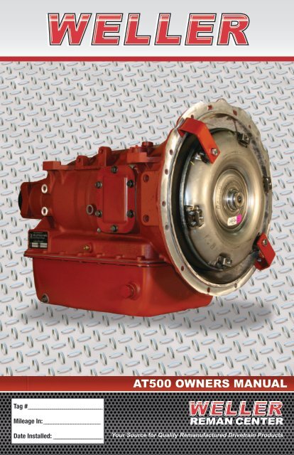
<strong>AT500</strong> <strong>OWNERS</strong> <strong>MANUAL</strong>Tag #Mileage In: Date Installed: REMAN CENTERYour Source for Quality Remanufactured Drivetrain Products
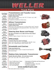
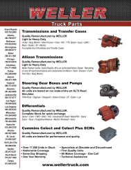
WELLER REMANThe Nation’s Complete Drivetrain Program!Transmissions and Transfer Cases –Quality Rebuilt by WELLER in Grand Rapids, MI.Light to Heavy Duty.Borg Warner • Clark • Cotta • Fuller • FWD• IHC • Isuzu • Mack/PAI • Meritor/Rockwell• New Process GMC • New Venture • Noster• Oshkosh • Spicer/TTC • ZFA complete line of Auxiliaries and Transfer Cases.Allison Transmissions –Quality Rebuilt by WELLER in Grand Rapids, MI.Light to Heavy Duty.An Authorized Allison Dealer in Grand Rapids, MI,rebuilding off-road transmissions and components forAllison • Clark • IHC • Dresser • Funk• Twin Disc • Borg WarnerSteering Gear Boxes and Pumps –All units are tested on our state-of-the-artXLT3 Road SimulatorTRW-Ross • Saginaw • Sheppard • Vickers Pumps• ZF • Eaton • LukDifferentials –Complete Stock for quick exchange.Clark • FWD • GMC • IHC • Industrial/Off Road• Mack/PAI • Meritor/Rockwell • Spicer/Eaton• TerexMedium Duty Automatic Transmissions –Quality Rebuilt by WELLER in Grand Rapids, MI.All Units Dyno Tested.Aisin • Jatco • Isuzu • GMC • Ford • MercedesTHE WELLER REMAN NETWORK2
PROGRAMDESCRIPTIONWeller’s Unit Exchange program eliminates down time by getting you the <strong>parts</strong> youneed when you need them. With over 15 ,000 rebuilt transmissions and differentialsready to ship, we can help you eliminate your or your customer’s downtime. Considerbecoming a key partner in the industry’s leading drivetrain program today. With nocommitments and no minimums, we are the industry partner for you!Our aggressive reman program includes:• All Makes Coverage – One Call• Same Day Service• Obsolete and Discontinued Specialists• One-year Warranty• 15,000 Unit Stock – It’s AvailableToday!• Excellent Core Policy (call fordetails)• ASE-certified, manufacturer-trainedmechanics• Technical Support on QuestionsWELLER REMAN HAS THE ADVANTAGE!THE WELLER REMAN NETWORK3
ALLISONTRANSMISSIONS✔✔100% Genuine Allison✔✔Outstanding Availability✔✔Quality Remanufacturing✔✔Every unit dyno tested✔✔New Genuine Allison TorqueConverter on all AT Units✔✔Quality rebuilt valve bodiesmatched to original unit✔✔Priced for the best valueTwo year, unlimited mile warrantyon On-highway applicationsSix month warranty onOff-highway applicationsWeller Reman Center,Grand Rapids, MI is anAuthorized Allison DealerPopular ModelsAT540 Series1000/2000 SeriesB400, B500HD4560,HT740/750MD3060, MT643…..EVERYTHING!Remanufactured by experts in Allison transmissionsTHE WELLER REMAN NETWORK4
DYNO TESTINGAll transmissions aredyno tested with a loadto simulate real <strong>truck</strong>conditions.Every transmission isevaluated to ensureproper torque,no leakage,accurate shiftpoints, andcorrect mainpsi and clutchpressure.THE WELLER REMAN NETWORK5
INSTALLATIONGUIDETRANSMISSION ASSEMBLY NO._________________________________________________________________________VEHICLE MAKE AND MODEL_____________________________________________________________________________VEHICLE ID NO.__________________________________________________________________________________________MECHANIC’S NAME_____________________________________________________________________________________I. PROPER TORQUE• Drive cover bolts (AT 540) or flexplate nuts (AT 543) – 34-40 lb ft (46-54 N-m). AT 540 drive cover bolthas metric thread effective with MY 1979, S/N 155873. Correct torque for the metric bolt – 42-50 lb ft(57-68 N-m).............................................................................................................................................. ¨• Transmission housing to engine bell housing bolts (Tighten to vehicle manufacturers specifications.......... ¨• Transmission to frame or mounting bolts – 164-192 lb ft (223-260 N-m)................................................... ¨• Output flange to output shaft bolt (supplied with transmission); Grade 8 – 102-121 lb ft (138-164 N-m).... ¨• Companion flange or universal joint bolts (Tighten to manufacturer’s specifications).................................. ¨• Manual selector lever nut – 15-20 lb ft (20-27 N-m). Thread on manual selector shaft changed to metriceffective MY 1978, S/N 126740. Nut torque remains unchanged............................................................... ¨• PTO mounting bolts – 26-32 lb ft (35-43 N-m)........................................................................................... ¨• Modulator control retaining bolt, early models – 15-20 lb ft (20-27 N-m); later models – 10-16 lb ft(14-22 N-m).............................................................................................................................................. ¨• Parking brake mounting bolts, Grade 8 – 81-97 lb ft (110-131 N-m).......................................................... ¨• Bell cranks and cable support brackets to transmission – 42-50 lb ft (57-68 N-m).................................... ¨• Oil filler tube nut – 65-75 lb ft (88-102 N-m)............................................................................................. ¨• Oil drain plug – 15-20 lb ft (20-27 N-m).................................................................................................... ¨• Speedometer driven gear assembly to rear cover – 45-50 lb ft (61-68 N-m).............................................. ¨• Neutral start switch to transmission housing – 50-60 lb ft (68-81 N-m)..................................................... ¨• Reverse signal switch to transmission housing – 4-5 lb ft (5-7 N-m).......................................................... ¨• Oil lines to transmission – 15-22 lb ft (20-30 N-m).................................................................................... ¨II. OIL COOLER, AIR AND VACUUM LINES• Check for leaks.......................................................................................................................................... ¨• Check for tightness of connections............................................................................................................ ¨• Check routing of lines................................................................................................................................ ¨III. LINKAGEManual Selector• Check adjustment at all positions............................................................................................................... ¨• Check ease of movement........................................................................................................................... ¨• Check neutral safety switch (engine start in Neutral or Park only)............................................................... ¨• Check shift tower for correct detent and freedom of movement................................................................. ¨Mechanical Modulator Control• Check adjustment for proper shift points.................................................................................................... ¨• Check ease of operation............................................................................................................................ ¨• Check routing............................................................................................................................................ ¨Parking Brake• Adjust for proper clearance........................................................................................................................ ¨• Adjust for full apply and release................................................................................................................. ¨THE WELLER REMAN NETWORK6
INSTALLATIONGUIDEIV. DRIVELINE• Check for proper indexing of slip and universal joints................................................................................. ¨• Determine if angles are within .................................................................................................................. ¨• Check for excessive backlash.................................................................................................................... ¨• Lubricate universals and slip joints............................................................................................................ ¨V. FLUID SYSTEM• TES 389-295 fluid being used................................................................................................................... ¨• Fluid level correct for operating conditions................................................................................................. ¨• Dipstick properly marked (refer to Mechanic’s Tips, MT 1321 Section 1..................................................... ¨• Filler cap tight............................................................................................................................................ ¨• Filler tube tight at oil pan........................................................................................................................... ¨• Breather clean and free of restriction......................................................................................................... ¨• Checked for fluid leaks during operation.................................................................................................... ¨VI. POWER TAKE OFF• Backlash established................................................................................................................................. ¨• Controls connected and operative.............................................................................................................. ¨• Properly coupled to driven equipment........................................................................................................ ¨• Lube line from transmission properly routed and connected....................................................................... ¨VII. INSTRUMENTS, ELECTRICAL COMPONENTS• Speedometer and odometer – operable..................................................................................................... ¨• Oil temperature and pressure gauges........................................................................................................ ¨• Wiring and electrical connections – functional........................................................................................... ¨• Reverse signal circuit checked................................................................................................................... ¨VIII. ROAD TEST VEHICLE• Refer to Mechanic’s Tips, MT 1321, Section VI, for points to check ............................................................ ¨Weller Reman will honor most types of automatictransmission fluids used in our automatic remanunits. For specific Allison fluid informationrelating to current production units, please seewww.Allisontransmission.com.THE WELLER REMAN NETWORK7
APPROVEDLUBRICANTSTES295 Approved MarketerApprovalNumberProduct BrandnameAN-011001 Castrol Heavy Duty Lubricants TranSyndAN-031002 BP Lubricants Autran Syn 295AN-031003 Cognis Corporation Emgard 2805AN-031004 International Truck & Engine Company Fleetrite Synthetic ATFAN-051005 ExxonMobil Lubricants and Petroleum Specialties Company Mobil Delvac Synthetic AFTAN-071006 John Deere & Company HD SynTranAN-1010007 Volvo Trucks North America Bulldog Synthetic ATFAN-121009 Case New Holland CNH HD Synthetic ATFAN-121008 Shell International Petroleum Co. LTD. Shell Spirax S6 ATF A295TES-389Product Marketer Product Brandname NAmerica CAmerica Approval NumberBP Castrol Castrol ATF Heavy Duty Yes Yes AA-33182010BP Castrol Castrol ATF Heavy Duty Yes Yes AA-33192010BP Lubricants Castrol Heavy Duty Multi-Purpose ATF Yes Yes AA-32252007BP Lubricants Castrol Heavy Duty Multi-Purpose ATF Yes Yes AA-32362007Chevron Products Company Chevron Automatic Transmission Fluid HD-389 Yes Yes AA-32012007Chevron Products Company Chevron Automatic Transmission Fluid HD-389 Yes Yes AA-32202007Chevron Products Company Chevron Automatic Transmission Fluid HD-389 Yes Yes AA-32242007Chevron Products CompanyChevron Synthetic Automatic Transmission FluidHeavy DutyYes Yes AA-31992007Chevron Products Company Texaco Automatic Transmission Fluid HD-389 Yes Yes AA-32002007ExxonMobil Lubricants &Petroleum Specialties Co.Mobile ATF D/M Yes Yes AA-32792008Fuchs Petrolub AG Fuchs Titan ATF 4000 Yes Yes AA-32822010Petro-Canada Petro-Canada ATF D3M Yes Yes AA-32082007RavensbergerSchmierstoffvertrieb GMBHShell International PetroleumCo. LTD.Ravenol ATF III H Yes Yes AA-33072010Spirax S2 ATF A389 Yes Yes AA-33242011Shell Lubricants Donax TA-389 Yes Yes AA-32212007Shell Lubricants Donax TX Yes Yes AA-32332007THE WELLER REMAN NETWORK8
Why Shift LinkageIs ImportantThe shift lever on a transmission moves inside the valve body, which distributes main pressureto the various clutches in the transmission. If the valve is in between two clutch ports, mainpressure will be restricted to the clutch to move the <strong>truck</strong>. The result is transmission failure.Typical shift linkage adjustment complaints:1. Shift lever (in cab) does not line up with the gear selected.2. Slow engagement to forward or reverse.3. Truck creeps forward or backward in neutral.4. Reverse beeper operates intermittently in reverse or in neutral or not at all.Correction:One person is needed inside the cab and another person at the transmission shift lever. At thetransmission, remove the cotter key or retaining clip and remove the cable clevis pin from thetransmission shift lever. Have the person in the cab select each gear with the cable removed.Lock the shifter in each gear while the person at the transmission moves the lever to itscorresponding position and reinserts the clevis pin in and out freely. This needs to be done ineach gear. If failure of the clevis pin to line up with the lever after adjustment results, the cablemay be sticking and needs to be replaced or the lever /cable geometry is incorrect or the leverid too short or too long.Why modulator adjustment is important:The modulator is attached to the transmission to the rear or the shift lever and neutral safetyswitch. Its function is to vary the shift points depending on the throttle position. In otherwords, a part throttle condition (I.e. city driving) will result in an “early” or lower up shiftand a full throttle condition will result in a “later” or higher upshift. What happens when themodulator is not working properly is an early or too soon up shift at full throttle conditions.You may notice the engine RPM “flare” 200-300 RPM between shifts. Driving a <strong>truck</strong> thatshifts “too soon” will lug the engine and place undue stress on the transmission. Imaginedriving a manual transmission <strong>truck</strong> and you attempt a 3rd or 4th gear shift from a rolling stop.The clutch will try to absorb output torque load. But if it doesn’t the clutch slips. This sametheory applies with automatics.There are Four Different Types of Modulator:1. Cable Operated – One end will attach to either the engines governor/carburetor ordirectly to the accelerator pedal. The transmission end uses a fulcrum to move themodulator pin. This cable will either push or pull to full throttle depending on yourvehicles set up.2. Air – This modulator uses an air signal from the engine governor to move themodulator pin.THE WELLER REMAN NETWORK9(continued on page 10)
Why Shift LinkageIs Important(continued from page 9)3. Electric – Most commonly used with electronically governed engines where thegovernor has no mechanical moving <strong>parts</strong>. Electric modulators are either on oroff. They get their signal from engines ECU or data link translator to move themodulator pin.4. Vacuum – Only used on gas engines. Under full engine load, vacuum will drop off.This signal is relayed to the modulator via a tube or hose, actuating a diaphragminside the modulator and releasing the plunger outward. Once there is no load,vacuum will return, pulling the plunger back against spring pressure.Typical modulator Complaints:Downshifts HardCable Modulator – cable at pedal or governor is not fully returning to its relaxedposition. You may need a return spring to help the cable backVacuum Modulator – No vacuum signal or a torn diaphragm in modulatorAir Modulator – S<strong>truck</strong> plunger in modulator or full air pressure under all throttlepositionsElectric Modulator – Power to modulator on, under all throttle positionsUp shifts Hard (low RPM or too early)Cable Modulator – Cable not adjusted correctly or inoperable. To correctly adjust, pushor pull the throttle to full fuel. There should be no more than 1/8" slack left in the cable.Keep in mind there are mechanical <strong>parts</strong> inside the box end of the cable that do wear.Replacement of the cable may be necessary if adjustment won’t cure an early up shift.Air Modulator – seals inside the modulator have worn allowing air pressure into thecase, or low or no air pressure signal to the modulator. If you notice oil leaking out thebreather, chances are the air modulator is leaking.Electric Modulator – no power to modulator or modulator malfunctions. To checkloosen but do not remove the retaining clip. With the key on, engine off, fully depressthe throttle. This should push the modulator out away from the transmission. This testwill require one person in the cab and one person at the transmission. If no modulatoraction is observed, voltage tests will be required back to the source, usually a relay inthe cab.A harsh downshift may also be caused by higher than normal idle or slow to return throttle. Itmay also be caused by a sticky transmission governor valve. An early up shift may be causedby using two O-rings in the modulator valve. This happens quite often as most reman units areshipped with an O-ring already installed in the case. BE SURE ONLY TO USE ONE “O” RINGWHEN INSTALLING MODULATOR OR MODULATOR PLUG!THE WELLER REMAN NETWORK10
ALLISON JOB AIDAllison Job AidSHIFT SELECTOR AND CABLE ADJUSTMENT PROCEDUREFor Allison Transmission Models:1000 Product Family, 2000 Product Family, AT 500 Series, MT 600 Series,HT / CLT 700 SeriesThe shift cable must be adjusted after the shift selector has been installed in its permanent mounting location, theshift cable routing is finalized, and the cable has been secured.NOTE: All changes to the shift cable routing,including changes to the shift selectorlocation, will affect the adjustment of theshift cable. Therefore, the shift cable mustbe readjusted if its routing is modified bya body builder or during transmission orvehicle service.When properly adjusted, the handle of a lever shiftershould be centered in each gate position when thetransmission selector shaft is held in place by theinternal transmission detent. See Figure C–2.“Gates” inshift selectorpermit transmissiondetent to determineactual selectorshaft orientationRN5421Figure C–2. Proper Shift SelectorAdjustmentFollow procedure below to attach and adjust the shiftselector cable at shift lever on the transmission.1. With the engine off, set the park brake and blockthe wheels to prevent vehicle movement.2. Place both the shift selector and the transmissionselector shaft in the Neutral position.SHIFT LEVERHELD INNEUTRAL BYTRANSMISSIONDETENTPIVOTCABLE3. Attach the cable to the shift selector at theoperator’s station.4. At the transmission end of the cable, push thecable to move the shift handle against the end ofthe shift selector Neutral gate. Note the positionof the pivot at the end of the cable with respect tothe hole in the shift lever. Refer to Figure C–3.ñPush cable to moveselector handle againstend of NEUTRAL gate.Figure C–3. Proper Shift SelectorCable Adjustment5. Pull the cable to move the shift handle against the opposite end of the shift selector Neutral gate. Note theposition of the pivot at the end of the cable with respect to the hole in the shift lever. Refer to Figure C–4.6. Center the position of the cable at the midpoint of the travel determined by Steps 3 and 4. See Figure C–5.JA3344EN (2008/01)P.O. Box 894 Indianapolis, Indiana 46206-0894 (317) 242-5000 www.allisontransmission.comTHE WELLER REMAN NETWORK11
ALLISON JOB AIDSHIFT LEVERHELD INNEUTRAL BYTRANSMISSIONDETENTPIVOTCABLESHIFT LEVERHELD INNEUTRAL BYTRANSMISSIONDETENTCABLEPIVOTñPull cable to moveselector handle againstopposote end ofNEUTRAL gate.Figure C–4. Proper Shift Selector CableAdjustmentññCenter cable to midpoint of travel(midway between “push” and “pull” positions).Figure C–5. Proper Shift Selector CableAdjustment7. Holding the cable at the position determined in Step 5, rotate the pivot on the threaded section of thecable end until it is aligned with the hole in the shift lever. See Figure C–6.8. Verify that the attachment pin of the pivot does not bind in the shift lever hole and that the detent in thetransmission is positively engaged. This condition is sometimes called “free-pin-fit,” referring to lack offriction at the cable / shift lever interface oncethe transmission detent is engaged. RepeatSteps 4 through 6 as necessary to create thiscondition.9. Attach the pivot to the shift lever and secure withthe lock pin. If a jam nut is provided with thecable hardware, torque the jam nut to lock thepivot to the cable end as noted in Figure C–6. Ifthe cable manufacturer does not provide a jamnut with the cable assembly, do not add oneduring the installation process.CAUTION: Once the jam nut is tightened,the pivot pin should slide freely into the holein the lever. Do not twist the cable to insert itinto the lever. Loosen the jam nut, reorientthe pivot to insert freely into the lever, thentighten the jam nut again.SHIFT LEVERHELD INNEUTRAL BYTRANSMISSIONDETENT10. Once this attachment is made, move the selector through all the range positions at the operator’sstation. Verify that free-pin-fit exists in each range position, and that the position of the shift lever isdetermined by the internal transmission detent — not by tension or compression on the shift cable.Special attention should be devoted to the free-pin-fit in the Neutral position, in the lowest forwardrange (1), and, if available, in the Park or Park Brake position.ñññCABLEPIVOTRotate pivot on threaded end of cableuntil it is aligned with hole in shift lever.Verify “free pin fit” between pivot andshift lever. Install lock pin and torquejam nut (if present) to 8.5N-m (75 in-lb).Figure C–6. Proper Shift Selector CableAdjustmentJA3344EN (2008/01)www.allisontransmission.comTHE WELLER REMAN NETWORK12
SERVICE TIPSTHE WELLER REMAN NETWORK13
SERVICE TIPSTHE WELLER REMAN NETWORK14
CORE RETURNINSTRUCTIONSThe Weller Truck Parts core return program is designed to facilitate an efficientand cost effective way of returning your cores. Following the instructions listedbelow will insure your core is processed quickly and correctly.1. Attach the Core Return Tag provided with the remanufactured unitto core.⦁ For warranty units, obtain a Warranty Repair Authorization (RA#) from yourWeller Truck Representative. If you are not sure who your representative iscall the Reman Center at 1-800-872-6697 or email warranty@<strong>weller</strong><strong>truck</strong>.com.2. Prepare the unit for shipping.⦁ Drain oil from unit.⦁ Band, wrap, or strap unit(s) to a pallet.⦁ Attach a copy of the warranty invoice, core tag or RA# to the unit foridentification.3. Notify Weller Shipping Department when unit is ready for pick up.⦁ Email corereturn@<strong>weller</strong><strong>truck</strong>.com or call 1-800-872-6697 Ext. 3794 or 3759⦁ Provide the following:◆ Core return tag # or Weller Truck Parts invoice # or the RA# if the unit isa possible warranty◆ Your contact information◆ Hours of operation⦁ Weller will prepare the bill of lading and schedule your unit to be picked upby a Weller approved carrier.Thank you for choosing Weller Truck Parts.Failure to follow these procedures could result in core credit delays and freight charge backs.www.<strong>weller</strong><strong>truck</strong>.comTHE WELLER REMAN NETWORK15
WELLER WARRANTYWARRANTY STATEMENT• Nationwide• Two YearCoverage• UnlimitedMileage• 800-872-6697Tech LineForTroubleshooting• Call ForAuthorizationAndAssistance• Metal tag mustnot be removedor warrantywill be voidWarranty CoverageStandard Warranty CoverageWeller Reman Allison Transmissions for “on-highway” applications –Two year, unlimited mileage – <strong>parts</strong> and labor. Weller Reman AllisonTransmissions for “off-highway” applications – Six months, unlimitedhours – <strong>parts</strong> and labor.Authorized Repair Points – Our Nationwide Warranty may beadministered only by an authorized warranty repair facility. Call1-800-872-6697 for authorization.Exclusions – Subject to the conditions stated herein, Weller warrantsto the original retail purchaser thereof that its Reman productswill, when used in a motor <strong>truck</strong> for on-highway or on/off-highwayapplications in the United States and properly installed andassembled on vehicles approved by the O.E.M. for such purpose, beand remain under normal conditions of use and operation free fromfailure due to defects in materials and workmanship from the dateof sale.This warranty covers <strong>parts</strong> and labor to repair or replace, at Weller’soption, the failed Weller component. Units installed as replacementsunder this warranty are warranted only for the remainder of theoriginal warranty period.This warranty shall not extend to failures or damage due to improperlubrication or operation in excess of original design limitations,failure to follow normal published preventive maintenance guidelinesof the O.E.M., abuse or damage by improper installation, casualtyor shipment.This warranty shall not extend to repairs for noise (including idlerattle), excessive operating temperature, transmission rear sealleakage, nor does it cover failures caused by engine, clutch,driveline; including transmission synchronizer pin breakage, or other<strong>truck</strong> components or system.This warranty does not cover failures caused by a worn, damagedor defective part or component mounted to the unit by the dealeror retail purchaser, including without limitation, the transmissionend yoke.All warranty claims shall be made to Weller and shall be supportedby satisfactory evidence in respect of the conditions stated herein.As a condition precedent to the allowance of such claims, thecomponent or assembly involved shall, if requested by Weller, bereturned prepaid to Weller for examination.EXCEPT FOR THE EXPRESS WARRANTY STATED HEREIN,WELLER DISCLAIMS ALL WARRANTIES, EXPRESS OR IMPLIED,INCLUDING WITHOUT LIMITATION THE IMPLIED WARRANTIESOF MERCHANTABILITY AND FITNESS FOR A PARTICULARPURPOSE. THE FOREGOING IS THE LIMIT OF THE LIABILITY OFWELLER, AND IS THE EXCLUSIVE AND SOLE REMEDY OF THEPARTY TO WHOM THIS WARRANTY IS MADE. LIABILITY ON THEPART OF WELLER FOR DAMAGES, EXPRESSLY INCLUDINGCONSEQUENTIAL DAMAGES IS DISCLAIMED.This warranty may not be changed or modified in any way except inwriting by Weller.THE WELLER REMAN NETWORK16
WELLER WARRANTYCALL WELLER FIRST!Possible Warranty• Have the Weller Tag or Invoice Number ready when calling.• Provide the Make/Model and vocation of the <strong>truck</strong>.• Provide a detailed description of the problem• Weller will issue a Repair Authorization #Customer Repair(In Place Fix)Customer to determine failure/repaircost and get Weller approval beforework is started.Weller Repair(R&R)Weller to determine failure/repair costand get customer approval beforework is started.Unit Replaced(Exchange)• Weller ships replacement unit• Replacement unit is installed• Truck is up and running• Invoice your customer untilwarranty process is completeWarranty• Complete the work• Send the invoice to Weller.The Repair Authorization # willbecome the purchase order #.• Weller will pay agreed amountNon-Warranty• If non-warrantable failure,repair and dealers invoice yourcustomer.• Weller will invoice for unitrepaired by Weller.Customer returns possible warrantyunit to Weller for failure analysisWeller performs failure analysis anddetermines failure responsibilityFailure Analysis Not CompleteFailure Analysis CompleteDealersInvoice your CustomerWarranty• Complete the work• Send the invoice to Weller.The Repair Authorization # willbecome the purchase order #.• Weller will pay agreed amountNon-Warranty• If non-warrantable failure,repair and dealers invoiceyour customer.• Weller will invoice for unitrepaired by Weller.THE WELLER REMAN NETWORK17
Date:WARRANTY CLAIM FORMTAG #: ____________________1500 Gezon Parkway SWGrand Rapids, MI 49509616-724-2000800-872-6697Fax 616-365-5679Claim Contact Information:Name, Company, and Address:_________________________________________________________________________________________________________Phone: ___________________________Fax: ______________________________E-Mail: ___________________________Vehicle Owner Information:Name, Company, and Address:____________________________________________________________________________________________________________Phone: ____________________________Fax: _______________________________E-Mail: ____________________________Truck Information:Make:Model:Mileage:Vocation:Engine:VIN:COMPLAINTFluid Leak:Shifting:Noise:Vibration:Hard Steering:Contamination:Other:❏ Yes ❏ No❏ Yes ❏ No❏ Yes ❏ No❏ Yes ❏ No❏ Yes ❏ No❏ Yes ❏ No❏ Yes ❏ NoDescription of the Problem:________________________________________________________________________________________________________________________________________________________________________________________________________________________________________________________________________________________________________________________________________________________________________________________________________________________________________________________________________________________________________________________________________________________________________________________ADDITIONAL INFOChange with Speed?❏ Yes ❏ NoSuspension Modified Recently?❏ Yes ❏ NoChange with RPM?❏ Yes ❏ NoDriveline in Phase?❏ Yes ❏ NoDuring Acceleration?❏ Yes ❏ NoEngine Mounts Checked?❏ Yes ❏ NoDuring Deceleration?❏ Yes ❏ NoKing Pin Checked?❏ Yes ❏ NoWhen Stationary?❏ Yes ❏ NoHydraulic Brakes?❏ Yes ❏ NoFluid at Proper Level?❏ Yes ❏ NoSystem Flushed & Filter Replaced?❏ Yes ❏ NoFluid Clean?❏ Yes ❏ NoIs the Unit Getting Hot?❏ Yes ❏ NoVehicle Towed?❏ Yes ❏ NoRunning PTO?❏ Yes ❏ NoEMAIL TO: WARRANTY@WELLERTRUCK.COMFAX TO: 616-365-5679, WELLER TRUCK PARTS WARRANTY18
WELLER WARRANTYWarrantyIt is essential that Weller is contactedbefore the unit is removed from the vehiclefor warranty. Weller’s technician will assistin troubleshooting the problem. If the unitfailed, the unit will be filmed, documented,and warranty determined.The following are the maximum flat rates forfailures due to defective products orworkmanship:• Units do not have to be installed at aDealer to receive flat rate warranty• Flat Rate Warranty is available on overthe counter salesThe following table shows warranty flat rates forAllison transmissions:Allison ModelFlat Rate Credit1000 SERIES GM APPL $5001000 SERIES STD APPL $5002000 SERIES $5002400 SERIES $500AT540, 542, 542N, 545 $500AT545N, 545R $500B400R $800B500 $800B500R $800HD4060, HD4060P, HD4560 $800HT70, HT740, HT740RS $800HT750, HT750CRD, HT750DRD $800HT754, HT754CR, HT754CRD $800MD3060, MD3060P, MD3066P $700MD3560, MD3560P $700MT640, MT643 $600MT650, MT653 $600MT654 $600Authorized Weller Dealers call for warranty labor hours guidelines.THE WELLER REMAN NETWORK19
THE WELLER REMAN NETWORK2052318161561211097313241914178421211221Reman Center1500 Gezon Pkwy S.W.Grand Rapids, MI 49509616-724-2000800-872-66979Detroit, MI29826 W. Eight Mile RoadFarmington Hills, MI 48336248-473-1900800-473-190517Nashville, TN230 Molly Walton DriveHendersonville, TN 37075615-264-2750866-426-27502345Atlanta, GA5007 Clark Howell Highway,Suite AAtlanta, GA 30349404-768-9577877-768-9577Baltimore, MD899 Airport Park Rd., Ste. NGlen Burnie, MD 21061410-553-0443877-550-0443Birmingham, AL116 Total Solutions WayAlabaster, AL 35007205-685-0777866-535-0777Boise, ID8484 W. Victory RoadBoise, ID 83709208-331-1061888-331-106110111213Gaylord, MI353 Expressway CourtGaylord, MI 49735989-731-6700888-731-6700Houston, TX4549 Aldine BenderHouston, TX 77032281-442-8855877-677-8855Jacksonville, FL10330 Chedoak CourtSuite 205Jacksonville, FL 32218904-757-0777888-474-0777Las Vegas, NV2985 Coleman St., Suite 14North Las Vegas, NV 89032702-638-8222866-764-822218192021Omaha, NE8623 S. 117th St.LaVista, NE 68128402-597-9000855-597-9001St. Louis, MO2388 Chaffee DriveMaryland Heights, MO 63146314-692-2227877-992-2227Seattle, WA6408 South 196th StreetKent, WA 98032253-872-0321877-572-0321South Bend, IN3303 William Richardson Ct.Suite 200South Bend, IN 46628574-237-1000800-968-8860678Chicago, IL11152 Southwest HighwayPalos Hills, IL 60465708-974-9919888-974-9319Columbus, OH2885 International St.Columbus, OH 43228614-771-9500866-771-9501Dallas, TX3113 Skyway Circle NIrving, TX 75038972-258-0460855-258-0460141516Los Angeles, CA9355 Cherry Ave.Fontana, CA 92335909-356-8322877-356-8322Milwaukee, WI8625 North 107thMilwaukee, WI 53224414-354-6400877-354-6400Minneapolis, MN3201 85th Avenue NorthBrooklyn Park, MN 55443763-424-3800877-424-3802222324Tampa, FL217 Hobbs StreetSuite 103Tampa, FL 33619813-685-6100866-685-6109Salt Lake City, UT3450 W. California Ave.Suite 400Salt Lake City, UT 84104801-886-0100855-847-0100Denver, CODrive Train Industries