LCD TV SERVICE MANUAL - diagramas.diagram...
LCD TV SERVICE MANUAL - diagramas.diagram...
LCD TV SERVICE MANUAL - diagramas.diagram...

You also want an ePaper? Increase the reach of your titles
YUMPU automatically turns print PDFs into web optimized ePapers that Google loves.
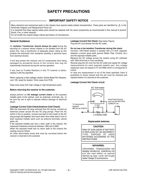
SAFETY PRECAUTIONSIMPORTANT SAFETY NOTICEMany electrical and mechanical parts in this chassis have special safety-related characteristics. These parts are identified by in theSchematic Diagram and Replacement Parts List.It is essential that these special safety parts should be replaced with the same components as recommended in this manual to preventShock, Fire, or other Hazards.Do not modify the original design without permission of manufacturer.General GuidanceAn isolation Transformer should always be used during theservicing of a receiver whose chassis is not isolated from the ACpower line. Use a transformer of adequate power rating as thisprotects the technician from accidents resulting in personal injuryfrom electrical shocks.It will also protect the receiver and it's components from beingdamaged by accidental shorts of the circuitry that may beinadvertently introduced during the service operation.If any fuse (or Fusible Resistor) in this <strong>TV</strong> receiver is blown,replace it with the specified.When replacing a high wattage resistor (Oxide Metal Film Resistor,over 1W), keep the resistor 10mm away from PCB.Keep wires away from high voltage or high temperature parts.Before returning the receiver to the customer,always perform an AC leakage current check on the exposedmetallic parts of the cabinet, such as antennas, terminals, etc., tobe sure the set is safe to operate without damage of electricalshock.Leakage Current Cold Check(Antenna Cold Check)With the instrument AC plug removed from AC source, connect anelectrical jumper across the two AC plug prongs. Place the ACswitch in the on position, connect one lead of ohm-meter to the ACplug prongs tied together and touch other ohm-meter lead in turn toeach exposed metallic parts such as antenna terminals, phonejacks, etc.If the exposed metallic part has a return path to the chassis, themeasured resistance should be between 1MΩ and 5.2MΩ.When the exposed metal has no return path to the chassis thereading must be infinite.An other abnormality exists that must be corrected before thereceiver is returned to the customer.Leakage Current Hot Check (See below Figure)Plug the AC cord directly into the AC outlet.Do not use a line Isolation Transformer during this check.Connect 1.5K/10watt resistor in parallel with a 0.15uF capacitorbetween a known good earth ground (Water Pipe, Conduit, etc.)and the exposed metallic parts.Measure the AC voltage across the resistor using AC voltmeterwith 1000 ohms/volt or more sensitivity.Reverse plug the AC cord into the AC outlet and repeat AC voltagemeasurements for each exposed metallic part. Any voltagemeasured must not exceed 0.75 volt RMS which is corresponds to0.5mA.In case any measurement is out of the limits specified, there ispossibility of shock hazard and the set must be checked andrepaired before it is returned to the customer.Leakage Current Hot Check circuitTo Instrument’sexposedMETALLIC PARTSAC Volt-meter0.15uF1.5 Kohm/10WReplaceable batteriesCAUTIONRISK OF EXPLOSION IF BATTERYIS REPLACED BY AN INCORRECTTYPE. DISPOSE OF USEDBATTERIES ACCORDING TO THEINSTRUCTIONSGood Earth Groundsuch as WATER PIPE,CONDUIT etc.ADVARSELLithiumbatteri - Eksplosionsfare vedfejlagtig hándtening. Udskiftning mákun ske med batteri at sammefabrikat og type. Levér det brugtebatteri tilbage til leverandorenCopyright © 2007 LG Electronics. Inc. All right reserved.Only for training and service purposes- 3 -LGE Internal Use Only