Flexiguide Brochure - Arva-RF
Flexiguide Brochure - Arva-RF
Flexiguide Brochure - Arva-RF

Create successful ePaper yourself
Turn your PDF publications into a flip-book with our unique Google optimized e-Paper software.
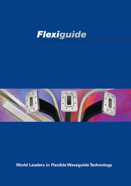
<strong>Flexiguide</strong><br />
World Leaders in Flexible Waveguide Technology
2<br />
The Company<br />
<strong>Flexiguide</strong> specialize in the<br />
manufacture of flexible and<br />
flexible / twistable waveguide and<br />
associated waveguide products.<br />
Using advanced manufacturing<br />
techniques and innovative<br />
processes, we can offer rapid<br />
delivery and exceptional<br />
performance.<br />
Our dedication to customer<br />
service and value has established<br />
our reputation for being the<br />
supplier of choice in a global<br />
market, not just for the product<br />
we supply, but for the service we<br />
provide.<br />
Our rapidly growing production<br />
facility in the UK supplies many of<br />
the Worlds leading OEM’s<br />
through direct sales and<br />
a network of agents.<br />
State of the art test<br />
equipment.<br />
<strong>Flexiguide</strong> modern manufacturing premises.<br />
In-house production lines.<br />
<strong>Flexiguide</strong><br />
“Delivering reliable performance”<br />
Quality<br />
Design and<br />
Development<br />
Our flexible / twistable waveguide is<br />
manufactured using purpose built,<br />
precision winding machines, designed<br />
and built in house using innovative new<br />
techniques in precision metal<br />
manipulation. The unique design of<br />
these machines has set new levels<br />
of performance for flexible / twistable<br />
waveguide without the need to dent<br />
tune. Our engineering team are<br />
qualified with many years experience<br />
of waveguide and its' applications and can offer custom design<br />
solutions to meet<br />
your demanding<br />
requirements.<br />
Typical full band<br />
performance.<br />
<strong>Flexiguide</strong> is dedicated to providing the highest level of quality<br />
assurance. We are proud of our high manufacturing yields,<br />
excellent record of on-time delivery and product reliability.<br />
Rapid response to technical requests and price / delivery<br />
enquiries ensure customer satisfaction at all times.<br />
The company offers state of the art test<br />
and measurement facilities up to<br />
50 GHz. Unique serial numbers are<br />
allocated to all items and test results<br />
or plots are recorded and kept for<br />
a period of five years. Fully traceable<br />
materials are used at all stages of<br />
manufacture of our flexible waveguide<br />
products.<br />
Warehouse despatch centre.
Applications<br />
and Markets<br />
Flexible and flexible / twistable waveguide are<br />
used in a wide variety of telecom, satcom,<br />
military and aerospace applications. Waveguide<br />
carries the high frequency radio (microwave)<br />
signals in both communication and radar<br />
systems. Due to its’ helically wound design,<br />
flexible / twistable waveguide can be<br />
simultaneously twisted and bent in both planes.<br />
The principle applications are:<br />
An aid to positioning parabolic<br />
reflectors in line of sight<br />
microwave radio links.<br />
The elimination of installation<br />
difficulties caused by<br />
misalignment or system<br />
variations.<br />
To isolate vibration.<br />
To permit the relative movement<br />
of equipment due to thermal<br />
expansion.<br />
To accommodate moving<br />
equipment in radar scanners.<br />
TELECOM<br />
Source: SES ASTRA<br />
SATCOM<br />
Photograph by: Mark Owens © Crown Copywrite/MOD image<br />
from www.photos.mod.uk<br />
MILITARY<br />
AEROSPACE<br />
3
4<br />
Waveguide Construction<br />
Flexible /<br />
Twistable<br />
Flexible / twistable waveguide core starts<br />
life as a spool of 0.1mm thick, silver<br />
plated, brass strip. The strip is then<br />
precision rolled into a three-dimensional<br />
profile before being helically wound<br />
around a rotating mandrel to form<br />
a continuous rectangular tube with<br />
uniform cross section and internal silver<br />
plating to minimize loss.<br />
Flexible / twistable waveguide is not<br />
pressure tight without a jacket.<br />
Flexible Waveguide<br />
There are two types of flexible<br />
waveguide:<br />
Flexible / non-twistable waveguide which<br />
is manufactured in a similar way to<br />
flexible / twistable waveguide with the<br />
addition of a solder wire which is later<br />
melted to prevent the waveguide twisting.<br />
This also reduces any <strong>RF</strong> leakage.<br />
Seamless flexible waveguide is<br />
manufactured from a thin brass tube,<br />
which is mechanically manipulated into<br />
a corrugated form to produce a seamless<br />
flexible waveguide. The seamless<br />
construction generally allows for greater<br />
power and pressure handing although<br />
length is limited to 1 metre.<br />
Flanges<br />
<strong>Flexiguide</strong> offer a wide variety of flanges<br />
including European "154 IEC" standard,<br />
American MIL specification "UG" flanges and<br />
American EIA "CPR" types. Standard flanges<br />
are CNC machined from corrosion resistant,<br />
marine grade brass and are supplied un-plated<br />
unless otherwise specified. Special flanges can<br />
be supplied upon request.<br />
The unique design of the flange rear ensures<br />
that the moulded rubber jacket overlaps to<br />
create a secure, permanent environmental seal.<br />
Flange Finish<br />
Tin<br />
Tin plating improves the compatibility of<br />
standard brass flanges with aluminium by<br />
reducing differential electrode potentials.<br />
It also provides increased resistance to<br />
corrosion in hostile environments.<br />
Silver<br />
Silver plating of the flanges provides increased<br />
corrosion resistance for hostile environments.<br />
Protective<br />
Jacket<br />
Silicone:<br />
-70 to 170 o C<br />
Our standard flexible<br />
waveguide is encapsulated<br />
using injection moulded<br />
silicone rubber to provide<br />
a high degree (IP68) of<br />
environmental protection.<br />
Silicone is proven to be more<br />
resistant to ozone, UV, water<br />
and extremes of temperature<br />
than the inferior neoprene<br />
alternative offered by other<br />
waveguide manufacturers.<br />
Polyurethane:<br />
-30 to 90 o C<br />
Polyurethane offers an<br />
excellent alternative to<br />
neoprene where the<br />
temperature range of silicone<br />
is not required.<br />
Polyolefin:<br />
-20 to 100 o C<br />
For a limited number of<br />
applications and for longer<br />
lengths we can offer an<br />
adhesive lined polyolefin<br />
heat-shrink jacket. Due to the<br />
nature of the jacket, moulds<br />
are not required and lengths<br />
up to 5 metre are available<br />
depending upon waveguide<br />
size. These jackets are not<br />
recommended for use in<br />
pressurised systems above<br />
40kPa.
ELECTRICAL SPECIFICATIONS<br />
WG FREQUENCY PEAK<br />
SUGGESTED<br />
AVERAGE INSERTION<br />
DESIGNATION RANGE POWER** POWER<br />
LIMIT**<br />
LOSS dB<br />
RETURN LOSS dB*<br />
WG WR R GHz MW kW dB/m 300mm 600mm 1000mm<br />
10 284 32 2.60-3.95 2.2 4 0.11 31.4 30.0 29.5<br />
11A 229 40 3.30-4.90 1.8 4 0.15 31.0 29.5 28.8<br />
12 187 48 3.95-5.85 1.4 3 0.16 31.0 28.8 28.3<br />
13 159 58 4.90-7.05 0.6 2.5 0.18 31.0 28.3 27.8<br />
14 137 70 5.85-8.20 0.56 2 0.28 30.2 27.8 27.3<br />
15 112 84 7.05-10.00 0.33 1.5 0.30 30.2 27.3 27.1<br />
16 90 100 8.20-12.40 0.22 1 0.40 30.2 27.1 27.0<br />
17 75 120 10.00-15.00 0.18 0.75 0.50 29.4 27.0 26.4<br />
18 62 140 12.40-18.00 0.12 0.4 0.80 29.4 26.4 26.0<br />
19 51 180 15.00-22.00 0.085 0.2 1.00 26.4 25.0 24.5<br />
20 42 220 17.70-26.50 0.045 0.1 1.20 23.0 22.1 21.1<br />
21 34 260 22.00-33.00 0.031 0.085 1.50 22.1 21.0 20.0<br />
22 28 320 26.50-40.00 0.022 0.075 2.00 21.0 17.7 17.1<br />
23 22 400 33.00-50.00 N/A N/A 2.50 20.0 16.5 16.0<br />
24 19 500 40.00-60.00 N/A N/A<br />
25 15 620 50.00-75.00 N/A N/A<br />
Notes:<br />
1) *Return Loss performance is degraded if Choke Flanges are specified.<br />
2) **Power figures are for guidance only.<br />
MECHANICAL SPECIFICATIONS<br />
MINIMUM CENTRE LINE BENDING RADII<br />
WG MAX TWIST MAX TWIST<br />
DESIGNATION STATIC STATIC REPEATED REPEATED STATIC REPEATED<br />
E-PLANE H-PLANE E-PLANE H-PLANE<br />
WG WR R mm mm mm mm Deg/m Deg/m<br />
10 284 32 206 412 824 1648 105 25<br />
11A 229 40 166 332 654 1328 130 35<br />
12 187 48 136 272 544 1088 155 40<br />
13 159 58 116 232 464 928 185 45<br />
14 137 70 100 200 400 800 210 52<br />
15 112 84 82 164 328 656 260 68<br />
16 90 100 66 132 264 528 315 76<br />
17 75 120 54 108 216 432 365 92<br />
18 62 140 46 92 184 368 445 112<br />
19 51 180 38 76 152 304 445 112<br />
20 42 220 30 60 120 240 630 157<br />
21 34 260 24 48 96 192 630 157<br />
22 28 320 20 40 80 160 920 230<br />
23 22 400 18 38 78 158 920 230<br />
24 19 500 18 38 78 158 920 230<br />
25 15 620 16 36 76 156 920 230<br />
Notes:<br />
1) Standard lengths are as follows: 100, 200, 300, 400, 500, 600, 900, 1000, 1200, 1500, 2000 mm.<br />
2) Other lengths are available on request and may be subject to tooling and design charges.<br />
3) Length tolerance = 1.5% or +/-2mm which ever is the greater.<br />
5
6<br />
Considerations<br />
for use<br />
Storage<br />
To prevent dirt and moisture ingress<br />
waveguide assemblies should be<br />
transported and stored in their original<br />
packaging until the point of installation.<br />
<strong>Flexiguide</strong> standard packing includes<br />
a sealed polythene moisture barrier to<br />
protect the contents form humidity<br />
and moisture ingress.<br />
Handling<br />
To maximize performance, waveguides<br />
are manufactured to high tolerances.<br />
Any physical damage or force, which<br />
alters the cross sectional profile,<br />
will be detrimental to the electrical<br />
performance. Waveguide assemblies<br />
must not be bent beyond the minimum<br />
bend radii as detailed in the mechanical<br />
specification table. Waveguide<br />
assemblies must not be stretched or<br />
installed under tension.<br />
Ordering Information<br />
Electrical<br />
Whilst Insertion Loss (attenuation) and<br />
Return Loss (VSWR) performance will be<br />
maintained during flexing, a flexible<br />
waveguide assembly cannot be<br />
considered phase stable during flexing<br />
due to the changing path length.<br />
Full details of the electrical performance<br />
can be found in the table on page 5.<br />
Environmental<br />
Humidity<br />
Jacketed waveguide assemblies are<br />
not affected by humidity, although<br />
condensation may penetrate<br />
non-sealed flanges.<br />
Vibration<br />
FT 15 K M 0600 T<br />
Waveguide assemblies have a low<br />
primary resonant frequency due to<br />
their low spring stiffness.<br />
Assemblies should therefore be<br />
supported at regular intervals to<br />
prevent large magnitude oscillations<br />
due to variable wind loading. In cold<br />
climates, consideration should also<br />
be given to potential ice loading and<br />
appropriate support provided.<br />
Flange Finish<br />
N = No plating (standard)<br />
S = Silver (optional extra)<br />
T = Tin (optional extra)<br />
Length in mm (use 4 digits)<br />
Second Flange Code<br />
Select from Chart<br />
First Flange Code<br />
Select from Chart<br />
Waveguide Designation<br />
Use British (WG - - )<br />
Core Type<br />
FT = Flexible Twistable<br />
FO = Flexible Only<br />
FS = Flexible Seamless (Silver Plated)<br />
FN = Flexible Seamless (No Plating)<br />
Place in<br />
alphabetical order<br />
Eg. The part number<br />
FT15KM-0600-T shown<br />
above describes a flexible<br />
twistable WG15, 600mm<br />
long with tin plated PBR<br />
and UBR flanges.
DESIGNATION<br />
WG WR R<br />
10 284 32<br />
11A 229 40<br />
12 187 48<br />
13 159 58<br />
14 137 70<br />
15 112 84<br />
16 90 100<br />
17 75 120<br />
18 62 140<br />
19 51 180<br />
20 42 220<br />
21 34 260<br />
22 28 320<br />
23 22 400<br />
<strong>Flexiguide</strong> flange codes<br />
154 IEC FLANGES<br />
CBR PBR UBR PDR UDR UAR PAR CAR<br />
4<br />
HOLE<br />
SQUARE RECTANGULAR CIRCULAR<br />
4<br />
HOLE<br />
154 IEC FLANGES<br />
4<br />
HOLE<br />
6<br />
HOLE<br />
8<br />
HOLE<br />
10<br />
HOLE<br />
6<br />
HOLE<br />
8<br />
HOLE<br />
10<br />
HOLE<br />
6<br />
HOLE<br />
8<br />
HOLE<br />
6<br />
HOLE<br />
8<br />
HOLE<br />
6<br />
HOLE<br />
8<br />
HOLE<br />
●H ●L ●Q ●R ●W<br />
●H ●L<br />
●H ●L ●Q ●R ●W<br />
●H ●L ●Q ●R ●W<br />
●H ●L ●Q ●R ●W<br />
●G ●K ●M ●H ●L<br />
●G ●K ●M ●H ●L<br />
●G ●K ●M ●H ●L<br />
●G ●K ●M ●H ●L<br />
●G ●K ●M ●H ●L<br />
●G ●K ●M<br />
●G ●K ●M<br />
●G ●K ●M<br />
7
DESIGNATION<br />
WG WR R<br />
10 284 32<br />
11A 229 40<br />
12 187 48<br />
13 159 58<br />
14 137 70<br />
15 112 84<br />
16 90 100<br />
17 75 120<br />
18 62 140<br />
19 51 180<br />
20 42 220<br />
21 34 260<br />
22 28 320<br />
23 22 400<br />
8<br />
AMERICAN FLANGES<br />
AMERICAN FLANGES<br />
UG-CHOKE<br />
(MIL-F-3922/-)<br />
UG-COVER<br />
(MIL-F-3922/-)<br />
UG-COVER<br />
+GASKET<br />
CPR ( )G CPR ( )F<br />
SQ CIRCULAR SQ CIRCULAR SQ CIRCULAR RECTANGULAR<br />
4<br />
HOLE<br />
6<br />
HOLE<br />
8<br />
HOLE<br />
4<br />
HOLE<br />
4<br />
HOLE<br />
Fixing Kits<br />
6<br />
HOLE<br />
8<br />
HOLE<br />
Sets of Nuts, Bolts, Washers and<br />
O-Rings / Gaskets are available to<br />
mate appropriate flanges. Each kit<br />
contains the correct hardware to<br />
mate correctly one pair of flanges.<br />
All fixings are corrosion resistant<br />
stainless steel.<br />
4<br />
HOLE<br />
4<br />
HOLE<br />
6<br />
HOLE<br />
8<br />
HOLE<br />
8<br />
HOLE<br />
10<br />
HOLE<br />
8<br />
HOLE<br />
10<br />
HOLE<br />
●C ●D<br />
●C ●D<br />
●A ●B ●Y ●C ●D<br />
●C ●D<br />
●A ●B ●Y ●C ●D<br />
●A ●B ●Y ●C ●D<br />
●A ●B ●Y ●C ●D<br />
●A ●B ●Y<br />
●A ●B ●Y<br />
●A ●B ●Y<br />
●A ●B ●Y<br />
●A ●B ●Y<br />
●B ●Y
<strong>Flexiguide</strong><br />
Other Products<br />
Rigid Waveguide Bends<br />
<strong>Flexiguide</strong> offer a range of Rigid E and H plane<br />
bends to suit a wide variety of applications.<br />
Standard bends are 90 degrees with<br />
30 and 45 degree models available upon<br />
request.<br />
Straight Rigid Waveguides<br />
Straight Rigid waveguides are available in sizes<br />
from WG10 (R32 / WR284) through to WG23<br />
(R400 / WR22). Lengths from 50 mm to 3000<br />
mm can be supplied to meet you requirements.<br />
Rigid Waveguide Twists<br />
<strong>Flexiguide</strong> offer a range of 90 degree Rigid<br />
waveguide twists to complement the other Rigid<br />
waveguide products.<br />
Taper or Stepped Transitions<br />
Taper or Stepped Transitions are available to<br />
convert from one waveguide size to another.<br />
Material and Finish for Standard<br />
Rigid Waveguides<br />
Bends, Twists, Straights and Taper Transitions<br />
can be supplied with any of the standard<br />
flanges listed in the <strong>Flexiguide</strong> Flange Code<br />
table and custom flanges are available upon<br />
request. Standard Rigid waveguides are<br />
manufactured from Brass / Copper and<br />
finished in matt black paint.<br />
90 0 H-Plane<br />
90 0 E-Plane<br />
Straight<br />
90 0 Twist<br />
Taper<br />
Please contact <strong>Flexiguide</strong> or your local <strong>Flexiguide</strong> Agent<br />
for further information.<br />
9
<strong>Flexiguide</strong><br />
<strong>Flexiguide</strong> Limited<br />
Unit 9<br />
Rodgers Industrial Estate<br />
Yalberton Road<br />
Paignton<br />
Devon TQ4 7PJ<br />
United Kingdom<br />
Telephone: +44 (0) 1803 527011<br />
Facsimile: +44 (0) 1803 553527<br />
Email: info@flexiguide.com<br />
Web: www.flexiguide.com<br />
Specifications shown on this document are offered as a guide only. Components may be modified to suit the mechanical or electrical parameters requested,<br />
or may be optimised to suit the operating frequency range. Frequency range of operation shall be advised when ordering.<br />
Information provided in this brochure is for reference only. Dimensions or specifications are typical values. All designs, specifications and availabilities of products<br />
and services presented in this document may be subject to change without notice. For confirmation of details please consult your agent or manufacturer.