CDI Ignition Electronic Ignition Overview ("The BIG Picture")
CDI Ignition Electronic Ignition Overview ("The BIG Picture")
CDI Ignition Electronic Ignition Overview ("The BIG Picture")

Create successful ePaper yourself
Turn your PDF publications into a flip-book with our unique Google optimized e-Paper software.
<strong>CDI</strong> <strong>Ignition</strong><br />
<strong>Electronic</strong> <strong>Ignition</strong> <strong>Overview</strong><br />
("<strong>The</strong> <strong>BIG</strong> Picture")<br />
This is a guide explaining the basic theory behind electronic ignition.<br />
This is linked from the (Vision <strong>Ignition</strong> FAQ) & my (Vision Home Page).<br />
If you have inputs to this page .... PLEASE email.<br />
I will update this for fellow Owners (Vision Riders Group).<br />
Last Update Sep2002<br />
Dave "Leather" Draper JET_AV8R@CSI.COM<br />
Download This Guide As PDF<br />
Review of basic ignition designs<br />
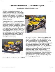
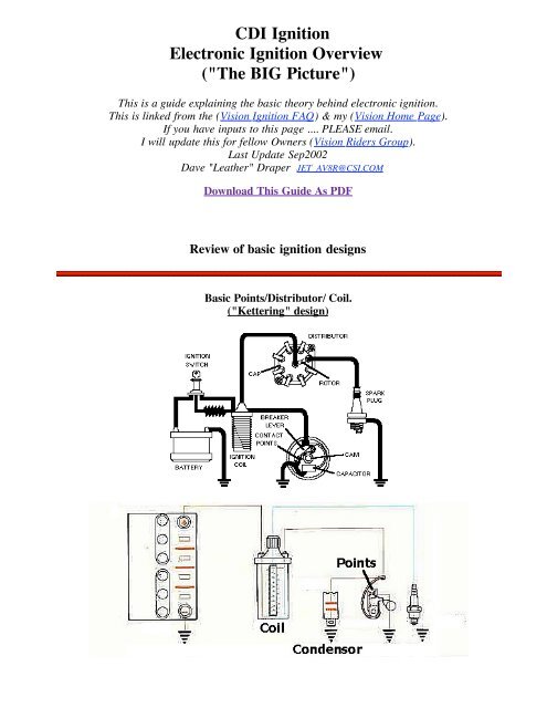
Basic Points/Distributor/ Coil.<br />
("Kettering" design)
A Frenchman named Etienne Lenoir invented the electronic spark plug in<br />
1860 but getting that spark plug to fire has been a long evolution. <strong>The</strong><br />
Godfather of ignition is Charles Franklin Kettering (man pictured left) Around<br />
1911 he invented the first electrical ignition system , the self-starter for<br />
automobile engines and the first practical engine-driven generator (known as<br />
the "DELCO" generator). <strong>The</strong>se were Patent Nos. 1,150,523; 1,171,055 . This<br />
type of iginition is known as the Kettering system (points/condenser/coil). It<br />
became the standard in the automotive industry replacing magnetos. It is a<br />
rugged and reliable but has drawbacks as you will see. A chain or belt from<br />
the engine drives a "DISTRIBUTOR". Inside this distributor is a spring loaded<br />
contact switch ("POINTS") riding on a revolving cam. <strong>The</strong> points would open<br />
and close to fire a single coil which would produce the spark. Inside the distributor is also a<br />
"ROTOR" which rotates to determine which plug wire gets the spark. To advance the<br />
"TIMING" of the spark a mechanical arm would adjust the position of the points relative to the<br />
rotating cam. As RPM increases spark starts to occur earlier. This is usually done by a<br />
centrifical weight or by using a vacuum diaphragm. <strong>The</strong> higher engine RPM vacuum would<br />
suck the diaphragm arm in advancing the points timing.<br />
A.To Coil<br />
B. Points<br />
C.Points Dwell<br />
Adjustment<br />
D. Point Riding On Cam<br />
E. Rotating Cam Driven<br />
.....by engine timing belt<br />
F. Condensor<br />
Magnetism and Induced Current
In the mid 1800's Michael Faraday (and others ... though "micro<br />
Farads " to this day is the measuement of capacitance)<br />
developed the concept that a current passing thru a coil wire<br />
creates a magnetic field. More importantly, a magnet passing<br />
by a coil wire creates a voltage current. <strong>The</strong> amount of<br />
current depends on the magnetic size and speed (rate) the<br />
magnetic field passes (or changes) by the coil. <strong>The</strong> math<br />
equation for this is e=-df/dt. <strong>The</strong> change in magnetic field<br />
strength is df and the time (rate of change) is dt. Technically, e is the "Induced EMF". But we<br />
talk of this as the current produced in the wire coil ... actually a PULSE.<br />
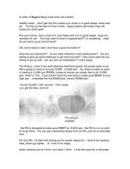
Automotive COIL (also called an "INDUCTOR")<br />
An iron core is wrapped with 2 long "coils" of wire.<br />
<strong>The</strong> "PRIMARY" winding on the outside and the<br />
longer "SECONDARY" winding on the inside. <strong>The</strong><br />
wire length ratio is typically 100:1.<br />
<strong>The</strong> coil is fed 12v to the primary winding. This in<br />
turn creates a large (enhanced by the iron rod)<br />
magnetic field which also surrounds the Secondary<br />
windings. <strong>The</strong> coil is now storing a large magnetic<br />
field (a Flux" field). When the +12v to the coil<br />
primary winding is turned off the magnetic ("flux")<br />
field inside the coil "collapses". This causes a "Back<br />
EMF" (Electro Motive Force) current in the primary<br />
wire of about 200-300volts. When the coil collapses<br />
this rapidly changing magnetic field is also transferred<br />
to the "Secondary" windings as current (remember ...<br />
a changing magnetic field passing by a coil!).<br />
<strong>The</strong> Secondary winding is 100 times longer so<br />
produces a voltage about 100 times more than the<br />
Primary during collapse. Lets do the math. <strong>The</strong><br />
Primary (sometimes called "Low Tension") wire is<br />
about 300v during the Back EMF spike. So the<br />
Secondary (sometimes called the "High Tension") wire is 100 x 300=30,000 volts. This high<br />
voltage is going somewhere, somehow to ground. <strong>The</strong> faster the power cutoff is, the faster the<br />
collapse, and the faster (more powerful) that spark is. So, when the points open (instantly<br />
cutting off power to the coil) 30,000 volts goes to ground via the spark plug.<br />
Due to magnetic "flux" properties (research Teslar and the "left hand rule"if you want to know<br />
more) the inductor (COIL) encourages current flow towards the plug. But the collapsing<br />
magnetic field also produces the phenomenon discussed above called "Back EMF". This 300+<br />
voltage spike can cause a mini-spark of it own across the points. To prevent this a<br />
CONDENSER is added.<br />
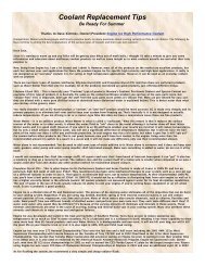
CONDENSER
<strong>The</strong> condenser is a large capacitor (only the automotive industry calls it a<br />
condenser?). It charges up to a smaller voltage. When the points open<br />
this small charge is dumped into the larger coil which slows its collapse.<br />
Remember, a coil output is strongest when the collapse is fast and sharp.<br />
<strong>The</strong> condenser slows this collapse just long enough for the points to get<br />
far enough apart so the coil back EMF output can't arc across that<br />
distance. Without a condenser the backflow arcing and heat would<br />
destroy the points (sometimes in a matter of seconds). However, the<br />
condenser can't be too big or the coil would collapse too slow and not<br />
produce any spark (especially at at higher RPM).<br />
Coil output is a function of coil windings "turns ratio" and also voltage input. <strong>The</strong> more power<br />
you put in the more you get out, right? But, points are a mechanical switch limited by how<br />
much current you can pump through them without burning them up. Points are limited to about<br />
250volts and 5 amps Coils can handle up to about 7 amps and transistor switches about 10-20<br />
amps.<br />
DWELL<br />
Conventional ignition is affected by "Dwell time" (or dwell angle). Dwell time refers to the<br />
time the points are closed thus recharging the coil. Dwell angle refers to the crankshaft angle of<br />
rotation made while the points are still closed. If dwell time (points closed) is too short the coil<br />
may not have enough time to recharge at high RPM. So large dwell is better right? But, if dwell<br />
is too large (points hardly open) then the points may not open at all (slop and wear) AND the<br />
points may not be open long enough for the coil to collapse (indirectly referred to as voltage<br />
"rise time"). <strong>The</strong> voltage rise time in conventional ignitions is about 80 microseconds, 125ish<br />
for TCI, and about 6microsec for modern <strong>CDI</strong>. Dwell limits the ability of points to deliver high<br />
power at high RPM. Race teams got around this by using dual point systems overlapping the<br />
dwell times to get what they needed.<br />
Problems with a conventional ignition system are:<br />
Points wear and erode (poor curent flow and sloppy timing)<br />
Points limit power output to coil (limiting coil output)<br />
Point dwell limits high power (no time to recharge the coil<br />
Points start to "float" and limit RPM<br />
Mechanical Advance would wear and get sloppy<br />
Points get wet and stop working<br />
Basic <strong>Electronic</strong> <strong>Ignition</strong>
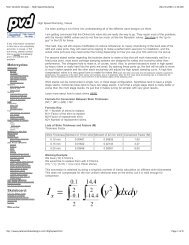
<strong>The</strong> first improvement of electronic ignition was to replace the mechanical points with a "solid<br />
state" semiconductor switch called a transistor (pictured above). This is called a "fast switching<br />
transistor" to be exact. <strong>The</strong> advantage of a transistor is that it can conduct up to near 400-500<br />
volts (more power than needed), is extremely accurate fast (in nanoseconds),and can last a long<br />
time in the heat / vibration of an engine. <strong>The</strong> trick of course if how to trigger the transistor<br />
switch. <strong>The</strong> common types of sensor systems that have evolved are: optical, magnetic, "Hall"<br />
effect, and (for trivia purposes only) "ECKO". In order of today's usage:<br />
"Hall Effect" Pickups<br />
Most Commonly Used in Modern Autos
This is the most widely used type of ignition sensor. <strong>The</strong> Hall effect (named after the American<br />
physicist Edwin Herbert Hall, 1855-1938) involves the generation of an "electric potential<br />
perpendicular to both an electric current flowing along a conducting material and an external<br />
magnetic field applied at right angles to the current upon application of the magnetic field". W-<br />
H-A-T ?!??. Practically speaking, a current is passed though a silican wafer. When a exposed<br />
to a magnetic field this disrupts the current flow and distributes more "potential" on one side of<br />
the wafer. This can be measured, conditioned, and amplified to trigger the ignition module. Hall<br />
Effect sensors are extremely accurate, they produce a "square" wave signal perfect for solidstate<br />
applications, and are very durable against heat / vibration. <strong>The</strong> rotor magnet does not need<br />
to be as strong (you may not feel its pull with a heavy screwdriver).<br />
Most Hall effect rotors involve a stationary Hall Switch and stationary magnet. What rotates is<br />
an "Interrupter Blade". When the blade passes between the sensor and the magnet it blocks the<br />
magnetic pull on the Hall Switch. When a "shutter blade" is open, the magnetic field projects<br />
onto the Hall Sensor switching it on. Again, a Hall system needs to be powered, so you will<br />
typically see 3 wires to it.<br />
Magnetic Pickups<br />
(Most common in everything other than Auto)
This is very popular and still used for many applications today because its a rugged durable<br />
design. In addition the sensor is not powered (like in Hall Effect) so it can be used in self<br />
powered magneto ignition applications. A coil sensor is used to detect the "flux" a magnet<br />
produces when it passes close by the sensor. This magnetic rotor is called a "Reluctor" (I betch<br />
ya didn't know that one). <strong>The</strong> problem with magnetic is that at higher RPM the sensor has<br />
trouble seeing "teeth" close together on the magnetic rotor. This is a bigger problem with many<br />
cylinder engines and/or high RPM applications. Also, you may remember magnets tend to loose<br />
their strength with vibration and heat. Also, reluctors are stronger magnets (you can definitely<br />
feel the pull if you get a screwdriver close) which tends to magnify things around it.<br />
Optical<br />
An infrared sensor triggers when a rotor blade<br />
blocks the light path. Although accurate, the sensor<br />
is sensitive to dirt and dust. This is not used much<br />
but is very common in aftermarket ignition kits<br />
because its easy to adapt to almost any application.<br />
ECKO<br />
"Eddy Current Killed Oscillator" systems were used by Lucas (yeah, the British "Dark Lord").<br />
It involves a 2 coil sensor that has current flowing. <strong>The</strong> sensor detects the current disruption<br />
cause by a magnet passing by. It is similar to "Hall Effect" in that it is extremely accurate and<br />
durable. But for whatever reason is only used mainly in manufacturing automation applications.<br />
Modern <strong>Electronic</strong> <strong>Ignition</strong> Modules<br />
For the most part, there are 2 types of ignition systems in use today (or variations of them):<br />
Induction ignition (TCI) or <strong>CDI</strong> ("Capacitive Discharge <strong>Ignition</strong>"). Both systems use a sensor<br />
(discussed above) to trigger a transistor switch (which has replaced the points). <strong>CDI</strong> is<br />
becoming the standard and you'll see why.
Induction <strong>Ignition</strong> (Kettering design):<br />
This is called an induction system because the coil is used as a power storage (an "inductor")<br />
device for the spark. Remember, the coil is powered up, stores near 30,000 volts, and unleashes<br />
it when the coil collapses (power supply cutoff). A feature of induction ignition is the slightly<br />
longer spark duration while the coil collapses. This is an advantage when starting and for<br />
igniting lean/high compression mixtures at high RPM. <strong>The</strong>se type of systems require coils<br />
meant for "induction" ignitions (they have a higher resistance typically than <strong>CDI</strong> coils).<br />
Induction ignitions are simpler in design (cheaper) and used often on less sophisticated motors<br />
(lawn, motorcycle, etc...)<br />
<strong>CDI</strong> ("Capacitive Discharge <strong>Ignition</strong>)<br />
Commercial developement of <strong>CDI</strong> happenned around the mid 60's. Up till then it was regarded<br />
as wothless and even dangerous. Well.. the dangerous part is somewhat right as you will see. If<br />
your really bored here's a 1965 sketch of an early <strong>CDI</strong> design and the bike it was tested on (a<br />
90cc Kawasaki motorcycle). Automotive <strong>CDI</strong> was pioneered mainly by Bosch in Europe. In<br />
1979 they introduced the "Bosch Motronic". Today we see a variety of names to include: Ford's<br />
TFI (Thick Film Integrated), GM's HEI (High Energy <strong>Ignition</strong>), DIS (Distributorless <strong>Ignition</strong><br />
System), ECU (electronic control unit), and many others.<br />
<strong>CDI</strong> ignition is most widely used today on automotive and marine engines. A <strong>CDI</strong> module has<br />
"capacitor" storage of its own and sends a short high voltage (about 250+ volts) pulse through<br />
the coil. <strong>The</strong> coil now acts more like a transformer (instead of a storage inductor) and multiplies<br />
this voltage even higher. Modern <strong>CDI</strong> coils step up the voltage about 100:1. So, a typical 250v<br />
<strong>CDI</strong> module output is stepped up to over 25,000v output from the coil. <strong>The</strong> <strong>CDI</strong> output voltage<br />
of course can be higher. So you'll see <strong>CDI</strong> systems claiming coil output capability over 40,000-<br />
60,000 volts!!? As you will see this is not exactly what happens at the plug but for math<br />
purposes it works out. <strong>The</strong> huge advantage of <strong>CDI</strong> is the higher coil output and "hotter" spark.<br />
<strong>The</strong> spark duration is much shorter (about 10-12 microseconds) and accurate. This is better at<br />
high RPM but can be a problem for both starting and/or lean mixture/high compression<br />
situations. <strong>CDI</strong> systems can and do use "low" resistance coils.<br />
AGAIN, the potential output of <strong>CDI</strong> coils can be over 40,000 volts.<br />
This can KILL!!<br />
Advantages / Disadvantages of <strong>Electronic</strong> <strong>Ignition</strong><br />
<strong>The</strong> advantages of solid state are numerous but the big one is : "no moving" parts. This should<br />
translate to control and reliability impossible to achieve in any mechanical system. <strong>The</strong> term<br />
"engine tuneup" is nearly meaningless with repect to modern ignition systems. Outside of<br />
replacing plugs and inspecting wiring there is not much else to do. More than a few mechanic<br />
shops exploit the public misunderstanding of modern engines. Having said that, the<br />
disadvantage of electronic ignition is simply reliability.<br />
A desktop computer circuit board should last a LONG time in theory, and yet you know quite<br />
clearly it does not sometimes. <strong>Ignition</strong>s have suffered the same evolution of making electronics<br />
that can stand the test of time. Early ignition systems were particularly prone to "component"<br />
breakdown. Anyone who has owned an older British sportscars will understand the term "the
dark Lord of Lucas" (Lucas <strong>Electronic</strong>s were notorious for failure).<br />
Solid state components are particularly sensitive to heat, thermal stress, vibration, moisture, and<br />
power surges (basically, everything an engine is about). So, great strides have been made to<br />
beef up and improve <strong>CDI</strong> reliability. <strong>The</strong>se include things like:<br />
Improved cooling and heat sinks<br />
Epoxy-rubber encasing components so they can't get wet<br />
Using seperate ignition modules for each plug (so a single failure won't kill the whole<br />
engine). This concept was first exploited in outboards where each plug has a seperate<br />
"power pack". Power pack failures were a big problem in the outboard industry for<br />
awhile and not funny when you are 60 miles from land in a small sport fisherman with 1<br />
engine.<br />
Heavier duty components that can withstand the heat, vibration, and "duty cycles".<br />
<strong>CDI</strong> TRIVIA<br />
"Dwell"<br />
Dwell time refers to the time the distributor points are closed. <strong>The</strong> dwell angle was the amount<br />
of rotation of the crankshaft that corresponded to the points being closed. This affects the<br />
charge time of the coil and hence spark length. Dwell was important then because at higher<br />
RPM the dwell time (points are closed to charge the coil) was not enough to fully charge the<br />
induction coil. That meant less voltage spark at higher RPM (...BAD). <strong>The</strong>re was also the<br />
problem of how fast a point could open and close without "floating" (a problem you have with<br />
valves also). <strong>The</strong>re was a real balance between dwell time at high RPM, how much voltage you<br />
needed for high RPM spark, how much voltage you could actually push thru a point without<br />
burning it up, and then what would happen at low rpm (long dwell times) when all that voltage<br />
was just heating up the coils.<br />
In newer <strong>CDI</strong> systems this term is near meaningless for several reasons. Solid state transistors<br />
control the discharge pulses electronically with near instantaneous timings. So the dwell times<br />
can be finely controlled to achieve the best coil / spark outputs for any given RPM. Transistors<br />
can handle a LARGE amounts of voltage/current (compared to points). And, newer generation<br />
coils are extremely fast. <strong>The</strong>ir coil pulse "voltage rise time" to the plug is VERY fast at around<br />
6 microseconds). So charge / discharge times are not a huge factor (unless racing). Newer<br />
racing ignitions (like MSD) are NOT producing bigger sparks with long durations but in fact<br />
getting more effecient burn by producing very controlled multiple short duration sparks to the<br />
plug.<br />
Timing Curves<br />
Timing curves can be manipulated in great detail to maximize engine horsepower. Replaceable<br />
"high performance" chips for many sportcars are routinely offerred by aftermarket companies as<br />
a byproduct of racing technology. While it seems logical that auto manufacturers already put<br />
the "best timing" they had in an engine design, they also may detune an engine slightly to<br />
address reliability and longevity of an engine. It has always been a balance between
performance (Horsepower) and "how long" an engine will last. You can often squeeze a few<br />
more HP out of an engine by improving the timing curves.<br />
<strong>The</strong> Big Myth: Your engine needs a tune up!<br />
If you've understood any of this then the question that should come to mind is: What do they<br />
adjust when you take your car in for a "tune-up", and they bill you $100's? <strong>The</strong> obvious<br />
answer: NOT MUCH !! If you own an older electonic ignition (80-late 90's) a shop can:<br />
Replace the spark Plugs<br />
Check the plug wires<br />
Check the wear and replace the distributor rotor (if there is one)<br />
Check the wear and replace the timing belt (if there is one)<br />
<strong>The</strong>re are no points to replace, no dwell or timing to change.<br />
In the "New Millenium" high-end car & marine engines have neither a timing belt,distributor,<br />
plug wires,etc... You guessed it., there ARE NO MOVING PARTS and NO ADJUSTMENTS.<br />
It either WORKS -or- IT DOESN'T. All they can do is change the spark plugs. AND YOU<br />
SHOULD. But for $200?!!<br />
Now... in fairness, the truth is: a dealer (or very good shop) WILL plug your high end machine<br />
into a $300,000 diagnostic computer which will tell wether all those sensors (you don't know<br />
about) are working correctly to produce max horsepower, best gas mileage, no knocking, and<br />
clean "California" exhaust so LA people can breath what little is left of their air and your<br />
catalytic converter doesn't have a Chernobyl meltdown. And... these things could be important.<br />
But generally, if your car is running good (no engine light).... just change your spark plugs<br />
occasionally (if you can find them) !?<br />
<strong>Ignition</strong> Considerations<br />
<strong>The</strong> common question is: how much power do you need in an ignition system? <strong>The</strong> more the<br />
better right? Well, not exactly. Lately it seems the talk is always centered around high voltage<br />
(50,000+) low resistance racing coils, aftermarket ignitions (MSD, Accel), etc... What is really<br />
important?<br />
Coil aspects: "Rise time" refers to the time needed for the coil voltage to reach 90% of its<br />
peak. Fast rise times are desired as they help prevent and breakdown plug fouling (or "plug<br />
tracking"). Plug fouling occurs when the spark is dissipated and runs to "ground" across<br />
deposits on the plug's surface instead of across the plug gap. <strong>The</strong>se deposits can be carbon<br />
buildup, corrosion, lead salts, water, etc. Rise times for ignition systems are typically 80-120<br />
microseconds for induction systems and 6 microsec for <strong>CDI</strong>.<br />
It takes about 12-14,000 volts to initiate the spark across the plug gap. After the initial arc the<br />
voltage required to sustain the arc is much less and drops off significantly. So while you may<br />
have a manufacturer claimed 60,000 volt racing coil you can't actually get that across the plug.<br />
Since the advantage of <strong>CDI</strong> is the higher coil output, how does that get used. Well, normally it<br />
doesn't. <strong>The</strong> extra power possible in the coil is "Reserve Voltage". As the plugs wear, fouling,
plug wires and connections get worse then the required firing voltage may go up 1-5,000 volts.<br />
So the "hotter" <strong>CDI</strong> coil output can help overcome these obstacles and the ignition system will<br />
last longer. So, its not that its working better.... but rather lasting longer that makes a hot coil<br />
good. <strong>The</strong> ideal coil output needed for normal applications is about 30,000 volts.<br />
High RPM / High Compression / Racing applications: Newer techniques are being used to<br />
increase spark output. Additionally, <strong>CDI</strong> typically has a very short spark duration near 10-12<br />
microseconds. As discussed you can't push more than about 20,000 volt across the plug without<br />
other stange phenomenon happening. If you were to try you would see arcing down the side of<br />
the plug, across carbon buildups at the electrode end, out any weak points in the wire<br />
insulation, connections, etc... So how do you get a better spark? Newer ignitions (like MSD-5<br />
for example) are outputting a finely controlled multiple spark pattern into the plug. Instead of<br />
one big spark a shower of short duration sparks are flooded across the combustion stroke. This<br />
makes for a much more efficient burn. Using this technique newer <strong>CDI</strong> can achieve longer<br />
spark duration times (near 250). This is particularly better for starting, lean mixtures (which are<br />
hard to ignite), and high compression situations.<br />
<strong>Ignition</strong> Future<br />
<strong>The</strong> GOOD NEWS is the ignitions systems are getting very reliable, accurate, and<br />
sophisticated. <strong>The</strong> BAD NEWS is that you can't work on it. I looked under the hood of a new<br />
Ford F-150several years back .... and .... "where's the spark plugs?" For that matter, where are<br />
the spark plug ....wires..... and ..... coil !??! Yeah, do I feel dumb.<br />
New generation auto ignitions are designed for more accuracy, better efficiency and reliability.<br />
This includes"crank angle" sensors to improve timing and fuel injection accuracy (example,<br />
mounting the Hall sensor and magnets on the flyheel). Newer coils will be wound around an<br />
"E" shaped pole (not "center wound"). <strong>The</strong>y will look like a square module and not the round<br />
cyclinder you've seen all these years.<br />
"DIRECT IGNITION" (first seen on Saab's and GM's ) will become the standard. Here you'll<br />
see separate coils mounted atop each spark plug. This improves spark power (no plug wires),<br />
accuracy, reduces RFI (radio frequency interference) problems, and most importantly eliminates<br />
the distributor (the last moving mechanical device to wear in ignition systems).
Timing and spark duration times will be adjusted across the RPM range. Additionally, timing<br />
advance will be calculated for a variety of inputs including increasing RPM vs. decreasing<br />
RPM (braking or coasting), throttle position, tempurature, altitude, etc. Even "engine knock"<br />
(detonation) will be eliminated by timing adjustments (using "listening" sensors like<br />
piezoelectric crystals bolted to the engine )<br />
This push towards a truly "no moving parts" ignition with reliability and amazing accuracy is<br />
the way of the future.<br />
Making Yours a Better <strong>Ignition</strong><br />
(For normal operations)<br />
Simple , and in order of importance: Plugs, Plug-wires, <strong>CDI</strong>, Coil.<br />
<strong>The</strong> biggest enemy against ignition is RFI and insulation leakage. Basically, you want the best<br />
insulated (thicker, 12mm?) and well made plug wires you can get. Remember this simple<br />
gradeschool phrase: "... electricity takes the path of least resistance". In the case of your engine<br />
this will be arc tracking across the plug and/or out the plug wires due to insulation breakdown.<br />
Upgrade your <strong>CDI</strong> module (example: performance timing curves, high output, etc...) if you want<br />
to spend a little more for higher performance. Although a good coil is always a plus, we've<br />
discussed how meaningless SOME manufacturers high output claims can be in practicality.<br />
In short, spend your money on a good well insulated system. As long as the coil and <strong>CDI</strong> can<br />
meet the rpm demand's of the engine you are on top of the game.<br />
Aftermarket <strong>CDI</strong><br />
Just throwing some names out here IN NO ORDER. Search on these to find more info on the<br />
web.<br />
MSD Accell<br />
Dynatek Boyer<br />
Intelligent<br />
Ign System<br />
(Iss)<br />
Lucas Rita