

Early German and American Radar Transmitter ... - Cdvandt.org
Early German and American Radar Transmitter ... - Cdvandt.org
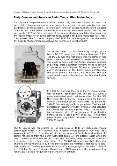
Early German and American Radar Transmitter ... - Cdvandt.org

Create successful ePaper yourself
Turn your PDF publications into a flip-book with our unique Google optimized e-Paper software.
The C. Lorenz company took part of the competitionwith the new FuMG 40L radar set. The large parabolicantennas <strong>and</strong> the new powerful DS 323 tube transmitterallowed an instrumented range of 50 km. Thedisplay unit was equipped with the typical <strong>German</strong>circular range scope. The new CRT of 168 mm diameterwith internal graticule enabled improvedrange accuracy. However, the Würzburg radar setfrom the competitor Telefunken showed a clear superiorityover the Lorenz device for gun laying. Evenwithout the so called Quirl (conical scanning systemantenna) the Würzburg A, demonstrated to militaryauthorities in July 1939, proved sufficiently good tobe used for firing targets obscured by clouds or fog,so Lorenz ceased production of the FuMG 40L set.In 1941 the C. Lorenz company started the preparation for the development of anairborne radar set. The later designation of this set was FuG 200 Hohentwiel, it wasplanned to use this equipment in airplanes for search <strong>and</strong> homing on surface ships<strong>and</strong> for navigation with l<strong>and</strong> echoes. For the development took the C. Lorenz companyadvantage from their earlier radar experience on 50 cm wavelength. The RLMspecification didn’t dictate that the antenna beam could be turned relative to theairplane, so scanning required turning of the plane, so the “Luftwaffe” - operationalprocedure intended that the airplane for search had to fly a full circle.The photo below shows the arrangement of the horizontal polarized Hohentwiel radarantennas installed on the nose of a JU 88 airplane. The upper Yagi array in thecentreline of the plane serves for transmitting, the left <strong>and</strong> right lower Yagi arraysserves for receiving. For a rather coarse direction finding of the target the receiverhad to be manually switched either to the left or the right array.The FuG 200 Hohenwiel airborne radar didn’t need a T/R switching device becauseof the separated transmit <strong>and</strong> receive antennas.Originally it was planned to use the Hohentwiel airborne radar in the JU 88, FW 200<strong>and</strong> HE 177 war planes of the <strong>German</strong> Luftwaffe, but later in WWII the powerfulHohentwiel radar set was used for many Naval applications as well as for groundbased radar systems too.2
As we have seen already, the FuG 200 transmitter was originally developed by theC. Lorenz company for the FuMG 40L antiaircraft artillery radar, but later used forthe FuG 200 Hohentwiel airborne radar. This airborne radar was laid out for search<strong>and</strong> homing on surface ships <strong>and</strong> for navigation with l<strong>and</strong> echo <strong>and</strong> also as a blind -bombing aid <strong>and</strong> for to launch air torpedo - attacks in conjunction with the FuG 102radio altimeter. It operated at the highest frequency so far used by the <strong>German</strong>s<strong>and</strong> is also remarkable among their sets in that the transmitter generated the highestRF peak power used in <strong>German</strong> as well as in Britain <strong>and</strong> <strong>American</strong> UHF airborneradars, to enable a detection range up to 150 kilometers. The <strong>German</strong> torpedobombersoperating over the Northern - Atlantic against the US ship - convoys, aswell as the <strong>German</strong> long - range bombers that carried the radio - controlled glidebombs, were equipped with the Hohentwiel - airborne radar system.The Hohentwiel airborne radar transmitter(shown here as open laboratory model)was derived from the DS 323 transmitter.Its push - pull grounded - grid oscillatorwas tuneable between 525 - 575 MHz. TwoLorenz RD12Tf triodes with oxide - cathodes(an improved version of the DS 323tube) were used as oscillator tubes. Thetransmitter was plate keyed by a thyratronmodulator with 10 kV, 2 µs pulses at apulse repetition rate of approx. 50 Hz. Thephoto shows on the top the plate resonantcircuit, it had six plate connections pertube. One of the two tuneable cathodelines is visible in the foreground. The bottomof the photo shows the Lecher line forsymmetric to asymmetric conversion ofthe RF-power by a Balun. The transmittergenerates an UHF pulse power of 30 kW.The schematic diagram of the Hohentwieltransmitteris shown beside. Feedbackvoltages for the tube cathodes are producedby voltage - dividing in the tube capacitiesC plate-cathode <strong>and</strong> C grid-cathode. Theadjustable cathode line circuits providephase control for the feed - back. The oscillatorfrequency is determined by theplate - circuit inductance, the lumped plate- circuit capacitances <strong>and</strong> the internal gridplatecapacitances of the tubes. For theseparation from the DC high - voltage potential,inductive coupling is employed betweenthe plate resonant circuit <strong>and</strong> theoutput. The UHF – output power is coupledvia the tuneable Balun - transformer.3
The photo shows the output circuitof the Hohentwiel - transmitter withthe inductive coupling loop <strong>and</strong> thetuneable balun transformer. Withthe adjustable stubs of the Lecherlines shown at the left of the photothe output circuit is tuned to resonancewith the transmitter frequency.The adjustable slide bar atthe right enables to match thetransmitter output to the load impedance.At the highest useful frequencies of triodes, the grid-return or grounded-grid circuitis of great importance for oscillators. The basic reason is the physical position of thegrid between cathode <strong>and</strong> plate in a triode.Grid-return oscillators can be made inwhich almost the only coupling betweenthe frequency-determining plate circuit<strong>and</strong> the feedback to the cathode circuit isproduced in the capacitive voltage dividerformed by the internal tube capacities C pk(plate-cathode 1.35 - 1.65 pf ) <strong>and</strong> C gk (grid-cathode 6.3 -7.7pf for the RD12Tf triode).The resonant-transformation effect necessary to supply the feedback voltages to thecathode circuits is produced by this capacitive voltage divider, so that the polarity ofthe returned voltage is correct <strong>and</strong> that the required step-down voltage ratio is provided.The RD12Tf transmitting-triode was developedin 1940 at the C. Lorenz tube laboratoryin Berlin, for radar applications. Likeits predecessor the DS323 tube, it wasfitted with an oxide cathode <strong>and</strong> was laidout for operation up to 600 MHz. Its constructionmeets the physical requirementsfor airborne use. As partly visible on thephoto, the tube has six plate pins <strong>and</strong>three grid pins. With forced air cooling theplate dissipation rating is 75 watts. Inplate-keying operation the tube may bepulsed up to 18 kV at sea level <strong>and</strong> generatean RF output power in the region of 50kW. For the Hohentwiel airborne transmittera plate pulse voltage of 9 kV was applied,but it was reduced above 3000 metersflight altitude, where the low pressurecaused arcing problems.4
At left, the socket outline <strong>and</strong> electricalschematic of the RD12Tf tube. The constructionof the tube system <strong>and</strong> the arrangementof the pins made it easy toemploy symmetric Lecher line resonantcircuits in push-pull oscillators.The inherent weakness of oxide-cathodes at high plate voltages limited the st<strong>and</strong>ingDC plate voltage of the RD12Tf to a maximum of 1000 volts. For applications in radarsystems with their typical high-power oscillators, the RD12Tf tubes cannot beoperated with grid-keying <strong>and</strong> its permanent high DC plate voltage. On the otherh<strong>and</strong>, plate-keying of power oscillators requires power pulse generators. Powerpulse generators used in the transmitters of radar systems are most commonly referredas modulator or pulser.Since the function of these generators is to provide the pulse voltage to the platesof the transmitter tubes <strong>and</strong> thereby produce pulses of high-frequency energy, theyhave to supply high pulse powers of, depending on transmitter efficiency, twice theradiated RF-power or more.In <strong>German</strong>y as well as in the U.S., as a result of the initial lack of pulse generators,early radar transmitters were operated with grid-keying. The problem of developmentpulse generators came from the lack of fast high-current switching devices.High-vacuum electron tubes are relatively unsuitable for high-current switching becauseof their inherent high power-resistance.<strong>Early</strong> gas-filled switch tubes like mercury thyratrons lacked the fast switching capability,required for pulse applications. In the U.S. as well as <strong>German</strong>y, experimentswere made with fixed <strong>and</strong> rotary spark-gaps as switching devices, but their reliabilitywere rather unsatisfactory.In 1941 the AEG Tube Laboratory at Berlin developedtwo small helium filled thyratrons (Layout according toLorenz Patent Nr. 132856) for pulse generator applications,the S1/3 <strong>and</strong> the S1/6 tubes. When the C. Lorenzcompany started the Hohentwiel program in 1941, it wasrealized that the bulky <strong>and</strong> heavy hard tube pulser of theFuMG 41L radar couldn’t be used for the airborne set. Anew sophisticated switching device was necessary tobuild the lightweight airborne modulator, necessary forthe powerful transmitter. On request of the Lorenz companyDr. Ahrens of the AEG tube works at Clausthal-Zellerfelde redesigned the S1/3 thyratron. With a largeareabarium-strontium-oxide cathode carrying a currentdensity of 40 amps/mm 2 , the S1/3iII type was created,as shown on the photo. Operated with 1000 volts was thetube able to switch a plate current of 500 amps at apulse length of 2 - 3 µs. It could operate with a repetitionrate up to 500 Hz. If operated with these parameters,the tube had an expected lifetime of 1000 hours. Withthe S1/3iII thyratron the switching requirements of the200 kW Hohentwiel - Pulsemodulator could be met.5
AEG Helium Thyratron S1/3iII Because of it’s extraordinary design the S1/3iII Helium Thyratron was afterWWII still manufactured in the DDR by the LKVO Berlin Oberspree.PPlate of the S1/3iII Thyratron6
A simplified functional diagram ofthe thyratron modulator appearson the left. At the end of thecharge cycle the capacitor C2stores an electrical energy of0.7 joules at 800 volts.As explained in the following functional description, the Hohentwiel modulator, inopposition to the common keying devices of the early WWII epoch, was of almost“genius” simplicity.An AC voltage of 500 Hz is used to supply the modulator circuit. Rectified by diodeD1, the unfiltered half-wave voltage charges the energy-storage capacitor C2through resistors R1 <strong>and</strong> R2. The time constant of R1 <strong>and</strong> R2, together with C2 isapproximately 20 ms – to reach the final charge, 10 cycles are required. As long thethyratron does not conduct, diode D1 prevents the discharge of C2. Before the thyratroncan fire <strong>and</strong> get conducting, the voltage at C2, as well as the voltage at thegrid of the thyratron, have to reach a certain trip level. The thyratron fires, if thevoltage at C2 at the end of the charge cycle has reached approx. 800 volts <strong>and</strong> ifthe grid voltage gets more positive than –10 volts. The initial high charging currentof C2 causes a high voltage drop at R1 <strong>and</strong> charges capacitor C1 to a relatively highnegative voltage, which is applied to the grid of the thyratron. The time constant ofR-C circuit R1 - C1 is calculated such that the decreasing charging current of C2does not compensate for its discharge. Therefore the negative voltage at the grid ofthe thyratron decreases slowly over the 500 Hz cycles. At the tenth have-wave cycle,the thyratron fires. This causes an instant discharge of the energy-storage capacitorC2 into the primary winding of the pulse transformer TR2 <strong>and</strong> induces ashort but high voltage pulse in the secondary winding. TR2 has a turn ratio of 1:24;it provides voltage <strong>and</strong> impedance transformation between the modulator <strong>and</strong> thetransmitter. The modulator circuit is dividing-down the 500 Hz half-wave cycles intothe repetition rate of 50 Hz for keying the transmitter tubes with 10 kV, 2 µspulses.The pulse transformer TR2 is the mostcritical component of the Hohentwielmodulator. Its development was a tradeoffbetween conflicting requirements. Thefigure shows the simplified equivalentcircuit for a pulse transformer.The most important purpose of the pulse transformer is the transformation ofthe stored energy in capacitor C2 into a waveform matched to the impedancelevel of the transmitter’s RF oscillator. An other requirement of the pulsetransformer is the need to generate a suitable pulse shape for the modulationof the transmitter.7
Parameters like the leakage inductance L l <strong>and</strong> the stray capacity Cd of the primaryund secondary winding, as well as unsuitable magnetic core material, can seriouslydegrade the transformer function. The leakage inductance can be reduced by dividingthe primary <strong>and</strong> the secondary windings in several parts.Measurements on the original Hohentwiel modulator have shown that, during thedischarge, much of the 0.7 joules energy stored in capacitor C2 is lost in the pulsetransformer. The reason is the limited saturation flux density <strong>and</strong> the high eddycurrentloss in the unsuitable magnetic core material available at the time of manufacturingin WWII.Upper Trace: Primary current of the pulsetransformer during the discharge of 0.7joules stored in capacitor C2.Vertikal deflection: 200 amps/divisionLower Trace: Secondary current of thepulse transformer supplied into the 1000ohms load, during the discharge of 0.7joules stored in capacitor C2.Vertikal deflection: 5 amps/divisionHorizontal deflection: 2 µs/divisionThe pulse shapes in the oscilloscope traces show that at the beginning of the dischargethe current in the transformer secondary winding follows the increase of theprimary current. When the magnetic flux density has reached saturation the secondarycurrent decreases into the pulse trailing edge, but the primary current startsincreasing again to a peak of approximately 500 amps before it decreases into thetrailing edge.However this second sharp rise of the primary current cannot increase the magneticflux density <strong>and</strong> therefore causes a loss of the remaining energy stored in capacitorC2; the energy is converted to heat <strong>and</strong> dissipated in the transformer.An experiment with the new pulsetransformer in the photo, built witha modern tape-wound toroidalcore of high saturation flux density<strong>and</strong> low eddy current loss, hasconfirmed that the power requirementsof the modulator can bemet with a reduced stored electricenergy of only 0.32 joules. For thereduction of the leakage inductancea subdivided winding configurationis employed.8
Upper Trace: Primary current of the newpulse transformer during the discharge of0.32 joules electric energy.Vertikal deflection: 100 amps/divisionLower Trace: Secondary current of thepulse transformer supplied into the 1000ohms load, during the discharge of 0.32joules electric energy, stored in capacitorC2.Vertikal deflection: 5 amps/divisionHorizontal deflection: 2 µs/divisionThe pulse shapes on the oscilloscope traces show, that the secondary transformercurrent follows the increase of the primary current up to the saturation level atapprox. 200 amps, then the secondary current decreases into the pulse trailingedge. The primary current begins to decrease too, but then it rises again until theextra energy of the storage capacitor is gone. With the new core material the secondarycurrent of 10 amps could be reached with 200 amps primary current. Thereis still some extra energy stored in the capacitor C2. The capacity of C2 could bereduced further without degradation the modulator performance.An experimental laboratory setup for the function ofthe Hohentwiel modulator, with the new pulse transformer.The two green wide-b<strong>and</strong> pulse transformersare used for measurement of the primary <strong>and</strong>secondary pulse currents. The unit at the bottomwith the brass bar is a 1000 ohms non inductivedummy load, simulating the transmitter load. Thepeak voltage of the high voltage pulse is measuredwith a Sensitive Research electrostatic crest voltagemeter.Project: <strong>Transmitter</strong> RF Peak-Power MeasurementStudies of reports published by the CIOS <strong>and</strong> BIOS teams about their investigationsin <strong>German</strong> industrial <strong>and</strong> government laboratories at the end of WWII as well asdocumentation of the U.S. National Bureau of St<strong>and</strong>ards, have shown that proceduresfor accurate RF peak power measurements at UHF or microwave frequenciesdid not exist, neither in <strong>German</strong>y nor in the U.S. at the time of WWII.So RF peak pulse power measurements on early UHF radars were a rather difficultventures.9
Surprisingly, however, the government laboratories <strong>and</strong> industrial companies, aswell as the military agencies, specified this parameter with tight tolerances, althoughneither st<strong>and</strong>ard methods nor accurate test equipments were available inthose days. The original technical specifications for the equipments found their wayinto the post-war literature, probably without further verification in most cases.The presumption is therefore obvious, that many of the specified RF peak powervalues were rather unreliable <strong>and</strong> probably to optimistic.Various methods for RF peak-power measurements at UHF <strong>and</strong> microwave frequencieshave been developed <strong>and</strong> st<strong>and</strong>ardized over the past fifty years.In general, the aim has been to develop instruments which indicate the measuredquantity directly. Indirect methods such as calculation of the pulse power from theaverage power are limited in accuracy, because they are strongly influenced bychanges in the duty cycle caused by pulse shape fluctuations, etc. It seems thereforeworthwhile <strong>and</strong> interesting to measure the RF peak pulse power of theHohentwiel radar transmitter with present-day instrumentation, as long as severalindependent sets of transmitting tubes are available in good conditions.For the RF peak power measurementsthe Hohentwieltransmitterwas operatedthrough a Narda directionalcoupler into a dummy load.The power was measuredwith a Boonton Electronicspeak-power sensor model56318, at the directionalcoupler <strong>and</strong> indicated on theBoonton Electronics model4530A peak-power meter.The pulse shape could beobserved either on the displayof the 4530A or withthe HP8472A detector.The Boonton Electronics 4530A Peak Power Meterin combination with the 57318 Peak PowerSensor, allows peak power measurements between+20 to -39 dBm with an accuracy of± 0.06 dB (2.1%).For the RF-peak power measurements five pairs of Rd12Tf triodes <strong>and</strong> two S1/3iIIthyratrons were available.S1/3iII thyratronsComparative measurements were made between the two S1/3iII thyratrons, but themeasurements did not indicate striking differences.10
Both thyratrons were operated with plate voltages of 800 volts <strong>and</strong> plate peak currentsup to 500 amps. Although the result of a comparison between only two samples,is not very impressive, it seems that the thyratron of the Hohentwiel modulatoris not a critical component. Earlier experiences with hydrogen thyratrons havemoved me to the conclusion that thyratrons either work fine or are broken!RD12Tf triodesComparative measurements of the RF peak powers were made with the five pairs ofRD12Tf. Average RF power measurements <strong>and</strong> their conversion to peak powers isproblematic because of the reduced accuracy of the result. The inherent low dutycycle of the Hohentwiel system, of approximately 0.000125 <strong>and</strong> the Gaussian distributionof the RF pulse shape make the conversions inaccurate. The average RFpower is in the region of only three to four watts.The power measurements were done at 525 MHzwith a plate pulse voltage of approximately 9 kV.For each tube pair the transmitter frequency hadto be adjusted on the plate resonant circuit. (Seethe plate tuning slide bar in the photo.The cathode lines in the photograph as well as theLecher line <strong>and</strong> the adjustable slide bar of thetransmitter output circuit were tuned for a maximumpower at 525 MHz.The RD12 Tf tube systems have a label with the serial number br<strong>and</strong> on the smallinternal sheet-metal connection between the two cathode pins. The results of powermeasurements below are referenced to these tube serial numbers.The following RF peak powers <strong>and</strong> plate peak currents were measured:RF DC to RFTube Serial Numbers Peak power Peak plate current Pulse width Efficiency(kW) (amps) (µs at -3dB)Ser. Nr. 0336 / Ser. Nr. 8540 32.4 9.5 2.8 38%Ser. Nr. A672 / Ser. Nr. G983 28.3 9.2 2.6 34%Ser. Nr. T686 / Ser. Nr. A409 30.4 9.8 2.6 34%Ser. Nr. V230 / Ser. Nr. 18064 31.5 9.4 2.8 37%Ser. Nr. T736 / Ser. Nr. G512 27.8 9.1 2.5 33%The equivalent dynamic resistance of the Hohentwiel transmitter was approximately1000 ohms.11
ConclusionThe measurements confirm that the RF peak power of the Hohentwiel transmitterwas in the region of 30 kW. This project has cleaned out some doubt about the correctnessof the specified RF peak power referenced in numerous documents <strong>and</strong>publications.Hohentwiel-Equipment with common transmit/receive antennaA modified version of the Hohentwiel equipment with a common rotatable transmit/receiveantenna array came in use later in WWII for the U-boats of the <strong>German</strong>Navy. For the separation of the transmit <strong>and</strong> receive path a T/R switch device wasnecessary, the so-called “Simultan-Gerät”. The T/R switch device must switch theantenna between transmitter <strong>and</strong> receiver rapidly <strong>and</strong> provide receiver protectionduring transmission.The figures below show the function of the T/R switch device:a. for the transmit caseb. for the receive caseGas-discharge tubes (<strong>German</strong> designation Nulloden) were utilized for the T/R switchdevice. The strong electric fields rapidly ionize the gas, thereby presenting a verylow impedance to the transmitted signal during the transmitted pulse.12
During reception, the T/R tubes passes the low-level receive signal with little insertionloss.The figure on the left shows a photo of the Telefunken LG 71 TRtubeutilized in the Hohentwiel-Simultangerät as switch device(in <strong>German</strong>y was the tube designated as a so called Nullode)The <strong>American</strong> ASB Airborne UHF Search <strong>Radar</strong> program.It is remarkable that the RF peak power of the <strong>German</strong> airborne Hohentwiel radartransmitter was far beyond those of the original <strong>American</strong> ASB airborne radartransmitters developed in the same period for the Navy’s carrier – based aircrafts.The ASB program began in the fall of 1941 when, <strong>American</strong> radar took to the air, itused first the British ASV airborne radar receiver <strong>and</strong> indicator, but a new transmitterdeveloped by the U.S. Naval Research Laboratory (NRL). British airborneradar then used a 200 MHz transmitter with a radically new transmitter tube notwell adapted to higher frequencies. But at 200 MHz the necessary radar beam antennaswere so large they were quite awkward on an airplane. It was necessary toreduce the antenna size drastically to avoid compromising the performance of the<strong>American</strong> aircraft, <strong>and</strong> the only way to do that was to use a much higher frequency.At that time the development had just been completed on a phenomenal new radartube by the EIMAC tube company. This new tube called the 15E, solved the problemsto develop 500 MHz transmitters with the high RF peak power necessary forairborne radars.Original NRL specification for the ASB radarWavelength <strong>and</strong> Function60 cm radar system designed for installation on carrier–based airplanes forsurface search.Research <strong>and</strong> Development ByResearch: Naval Research Laboratory, Washington (NRL)Development: Westinghouse Electric <strong>and</strong> RCAOperational RequirementsWeight 120 lbPower Supply 345 watts, 115 volts 1 phase, 600 – 1400 Hz13
PerformanceMax. Reliable Range on:Bombers, at 10’000 ft 6 mi.Battleships40 mi.Heavy Cruisers 40 mi.Destroyers30 mi.Submarines (surfaced) 5 mi. Cargo vessels 10’000 t. 40 mi. Minimum Range: 500 yd. Range Accuracy: ± 5 % Angular Accuracy: Azimuth: ± 1° SearchIdentical antennas mounted on each wing have 60° wide lobes in azimuth.Antenna can be rotated individually through 90° by operator. In searchingover open water, the antennas are oriented so that the lobes from the twoantennas are perpendicular to the line of flight. In homing, the lobes pointessentially parallel to the line of flight.Antenna SpecificationIdentical dipole arrays are mounted on each wing, only one antenna at atime being used.The antennas are switched at a rate of 1800 Hz. Each array has a beamwidth of 60° in azimuth <strong>and</strong> a gain of 14.7 dB. The antennas can be turnedindividually so that the beam from either one points in any direction betweenthelimits of 90° to the line of flights <strong>and</strong> essentially parallel the limitsof 90° to the line of flight <strong>and</strong> essentially parallel to it.<strong>Transmitter</strong> SpecificationEngineering problems involved in the design of the ASB airborne radar transmitteras well as changes in tactical <strong>and</strong> operational requirements caused thenecessity of making several versions of transmitters.The ASB-1 transmitter with two EIMAC 15E triodesFrequency: (RF) 515 MHzPulse Repetition Rate: (pps) 400 HzPulse Length: 2 µsRF Source: 2 EIMAC 15E TriodesPulser Type: Self Quenched Keyed Oscillation (Blocking Oscillator Principle)RF Peak Power: 5 kWRF Average Power: 4 wattsEnergy per pulse: 0.01 joules14
Original ASB-1 <strong>Transmitter</strong>with 2 EIMAC 15E Triodes(AN/APS-18)Developed 1941 at theNaval Research Laboratory,Washington DCFrequency 515 MHzRF Pulse Width 2 µsPRF 400 HzRF Peak Power 5 kWSelf-quenched keyed by alarge R-C time constant inthe grid circuit (see themica capacitor <strong>and</strong> thegrid resistor)The improved ASB-3 transmitter with four EIMAC 15E triodesFrequency: (RF) 515 MHzPulse Repetition Rate: (pps) 400 HzPulse Length: 2 µsRF Source: 4 EIMAC 15E TriodesPulser Type: Self Quenched Keyed Oscillation (Blocking Oscillator Principle)RF Peak Power: 10 kWRF Average Power: 8 wattsEnergy per pulse: 0.02 joulesImproved ASB-3 <strong>Transmitter</strong> with 4 EIMAC 15E TriodesDeveloped 1941 at the Naval ResearchLaboratory, Washington DCFrequency 515 MHzRF Pulse Width 2 µsPRF 400 HzRF Peak Power 10 kWSelf - quenched keyed by a large R-Ctime constant in the grid circuit (micacapacitor <strong>and</strong> grid resistor on the outsideof the housing)15
The improved ASB-7 transmitter with six EIMAC 15E triodesFrequency: (RF) tunable 515 – 530 MHzPulse Repetition Rate: (pps) 400 HzPulse Length: 2 µsRF Source: Ring circuit oscillator with 6 EIMAC 15E TriodesThe Ring Circuit Oscillator principle was a typically NRL design to increase the RFoutput power of the early VHF <strong>and</strong> UHF radar transmitters, it was first proposed bythe NRL expert Robert Morris Page on 1941.It was not limited to four tubes, it only is necessary that the number of tubes beeven. As the number of tubes is increased, however the difficulties with matchingof the tube parameters <strong>and</strong> the alignments of the ring circuitry arise. It was foundthat six tubes were very stable.Pulser Type: High power plate pulsed wide b<strong>and</strong> transmitterRF Peak Power: 50 kWRF Average Power: 8 wattsEnergy per pulse: 0.1 joulesImproved ASB-7 <strong>Transmitter</strong> with sixEIMAC 15E TriodesDeveloped 1944 at the Naval ResearchLaboratory, Washington DCFrequency was tunable 515 – 530 MHzRF Pulse Width 2 µsPRF 400 HzRF Peak Power 50 kWHigh Power Plate Pulsed Wide B<strong>and</strong>transmitter with a separate pulse modulatorunit.Schematic Diagram of the ASB-3 <strong>Radar</strong> <strong>Transmitter</strong> with 4 EIMAC 15E Triodes16
The design of the plate pulsed high power ASB-7 transmitter presented the NavalResearch Laboratory a lot of difficulties. Performance requirements necessitatedthe use of extremely high voltage in a limited space. At the beginning of production,it was learned that the data of the six EIMAC 15E oscillator triodes of the ringcircuit oscillator had to be matched carful <strong>and</strong> that the alignment of the ring circuitswas extremely critical. When the ring circuitry was correctly aligned by aWestinghouse developed procedure, the power output rose to such extent that coronaformed on some RF lines at high flight altitudes. These problems required agreat deal of engineering effort before they were solved <strong>and</strong> were responsible forseveral months delay in deliveries.Receiver SpecificationFrequency: 510 – 540 MHzType: Superheterodyne ReceiverIF B<strong>and</strong>width 1.4 MHzLocal Oscillator: 955 Acorn TubeMixer: 955 Acorn TubeIF Frequency: 55 MHzNoise Figure: 12 – 20 dBThe classical description of the superheterodyne receiver includes an RF amplifierat the front end. At uhf frequencies, however, an RF amplifier was notalways used. The original ASB radar receivers operated with the mixer asthe first stage of the receiver.The figure shows the frontend of the original ASB radarreceiver. The V-202 (RCA 955acorn tube) is used in a typicaltriode mixer circuit at frequenciesof 515 – 545 MHz.The local oscillator voltagefrom the V-201 (RCA 955acorn tube) enters the mixercircuit through the very smallcoupling capacity C-206. Themixer output (IF) signalflows over capacity C-207 tothe grid of the first IF amplifiertube V-203 (6AC7). TheIF frequency was 55 MHz.The noise figure of the receiverwas in the order ofmagnitude of 20 dB.17
In 1943 when suitable tubes for UHF RF amplification came available, theBell Telephone Laboratories developed an RF amplifier for the ASB-7 radarreceiver. The disk-seal tube or so called Lighthouse Tube utilizes a parallelplaneelectrode structure that allows very small cathode - grid spacing. Theconstruction lowers the electron transit - time <strong>and</strong> the inter electrode capacitances,so that the tube is useful as receiver oscillator <strong>and</strong> as RF amplifier atfrequencies up to 1000 MHz.The figure shows thefront end of the improvedASB-7B radar receiver.The front end consists ofa single stage of RF amplifier,a local oscillator,<strong>and</strong> a mixer. Lighthousetube type 446A <strong>and</strong> coaxial-lineresonators areemployed in the RF amplifier<strong>and</strong> mixer unit. In thelocal oscillator a Lighthousetube 446A is employedtoo, but the resonatoris of the parallel linetype. The local oscillatoris tuned by a variable diskcapacitance at the plateline.The connections betweenunits are made byshort sections of coaxialcable. Power coupledfrom the grid line of thelocal oscillator is appliedtogether with echo signalsfrom the RF amplifier,to the grid circuit ofthe triode mixer. A componentof the differencefrequency is produced atthe plate circuit of themixer <strong>and</strong> feed into the IFamplifier.The noise figure of the ASB-7B radar receiver with the lighthouse RFamplifierwas approx. 12 dB.18
Complete Schematic diagram of the ASB-1 ReceiverComplete Schematic diagram of the ASB-7 ReceiverIndication <strong>and</strong> Data Output5 inches CRT used with vertical sweep from bottom to top along a diameterof the screen. Signals from the port antenna produce horizontal pips to theleft while those from the starboard antenna produce horizontal pips to theright. Ranges 7, 28, <strong>and</strong> 70 Nautical Miles; some sets have 2 miles sweepcalibrated only at 1000 yards. The ASB-7A had improved indicator with 5000yards, 15, 50 <strong>and</strong> 150 Nautical Mile ranges <strong>and</strong> provisions for the laboratory.19
In 1940 the Eitel - McCulloughcompany at San Bruno CA hadjust completed on the phenomenalnew radar tube calledthe 15E. This new tube was adeceptive simple looking triode,about two inches in diameter<strong>and</strong> two <strong>and</strong> a halfinches long, but it was the resultof many months of intensiveresearch in electrode materials<strong>and</strong> electrode treating.It solved the problems of phenomenallyhigh cathode emissioncombined with fantasticallylow grid emission in theabsence of high anode temperaturesto keep the electrodesclean. The 15E had a directheated thoriated tungsten filament.The plate dissipation ofthe tube was 20 watts <strong>and</strong> itcould be operated up to a max.anode voltage of 12.5 kV.However, tubes with oxide coated cathodes like the <strong>German</strong> RD12Tf have an inherenthigher pulsed emission density (mA/cm 2 ) than tubes with thoriated tungstenfilaments. So transmitters equipped with oxide cathode tubes were able to generatea higher RF peak power with the same plate voltage, but on the other h<strong>and</strong> theyhad to be keyed on the anode <strong>and</strong> required power pulse modulators.Comparative measurements of the cathode emissions were done with a number of15E <strong>and</strong> RD12Tf triodes.The 15E triodes with the thoriated tungsten cathodeswere operated with a 5.5 filament voltage.The 15E’s showed typical cathode emissions in theregion of 4 amperes at a 10 kV anode peak voltage.For the measurements the tubes were operatedwith plate - grid connection as diode. The photoshows a 15E, with a plate heat dissipating connector,occasionally the filament emission test.The RD12TF’s with the oxide cathodes were operatedwith the highest allowed filament voltage of14.4 volts for pulsed operation. They showed typicalcathode emissions in the region of 10 amperesat a 10 kV anode peak voltage.In retrospect it may be pointed out that the development of the oxidecathode radar transmitting triode DS 323 by the Lorenz companywas very advanced in 1937, as well as the development of theS1/3iII Helium thyratron for the pulse modulator of the FuG 200Hohentwiel airborne radar by the AEG company in1941.20
In Britain even for the development of the pulsed microwave radarmagnetron on 1940, the application of oxide cathodes was an absoluteprerequisite to meet the RF power requirements.In the United States the thyratron application for radar pulse modulatorscame not in use before the end of WWII. The development ofthe Hydrogen thyratron began 1941 under Kenneth J. Germeshausen,but it was delayed by problems with the gas contamination<strong>and</strong> the gas clean - up in the tube. After WWII founded Kenneth J.Germeshausen together with Harold E. Edgerton <strong>and</strong> Herbert E. Grierthe EG&G company, EG&G is one of the largest supplier for Hydrogenthyratrons.AcknowledgmentThis project could not have been undertaken without the support of Ed Willi, GüntherHütter, Günther Riedl, Dieter Beikirch <strong>and</strong> Arthur Bauer. The author wish tothank these Gentlemen for providing some authentic key components, documentations<strong>and</strong> much advice.ReferencesMüller G. Funkmessgeräte Entwicklung bei C. Lorenz AG, 1935 – 1945, FirmeninternesArchivheft der SEL, 2. Erweiterte Fassung, Dezember 1981RLM Werkschrift 4108, Bordfunkmessgerät FuG 200, G. Kdos. August 1943RLM Vorschrift Nr. 75/790, Prüffibel für Bordfunkmessgerät FuG 200, Oktober 1944RLM Luftfahrtsröhren Ringbuch, Daten und Richtlinien über die Verwendung vonLuftfahrtsröhren, Januar 1945Dr. Steimel K. Bericht über den Zust<strong>and</strong> der Röhrentechnik in Deutschl<strong>and</strong> zum Abschlussdes Krieges, August 1945U.S. Air Material Comm<strong>and</strong> Dayton OH, Summary Report No. F-SU-1109-ND, TheHigh Frequency War - A survey of <strong>German</strong> Electronic War, 10 th May 1946CIOS Final Report 1746, <strong>German</strong> development of modulator valves for radar applicationsCIOS report XXX-36, Physikalisch-Technische Reichsanstalt, June 1945CIOS Report XXVII-46, Design of <strong>Radar</strong> Test Equipment at Siemens-Halske MunichBIOS Report 1228, HF Instruments & Measuring TechniquesAchievement in Radio, Radio Science, Technology, St<strong>and</strong>ards <strong>and</strong> Measurements atthe National Bureau of St<strong>and</strong>ards, US Department of Commerce, October 198621
Megla Gerhard, Dezimeterwellentechnik, Kapitel Messgeräte und Messmethoden beiDezimeterwellen, Fachbuchverlag Leipzig, 1952Radio Measurements, Proceedings of the IEEE, Volume 55, June 1967Hewlett Packard, Microwave Measurement H<strong>and</strong>book, Chapter RF Peak Power Measurement,Procedures <strong>and</strong> EquipmentsBoonton Electronics Company, Application Note AN-50, Measuring the Peak PowerU.S. Naval Research Laboratory, ASB <strong>Radar</strong> Alignment Procedure, November 194222


