Rack Product Range - ATLANTA Drive Systems, Inc.
Rack Product Range - ATLANTA Drive Systems, Inc.
Rack Product Range - ATLANTA Drive Systems, Inc.
- No tags were found...

You also want an ePaper? Increase the reach of your titles
YUMPU automatically turns print PDFs into web optimized ePapers that Google loves.
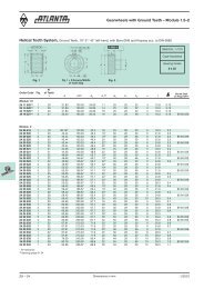
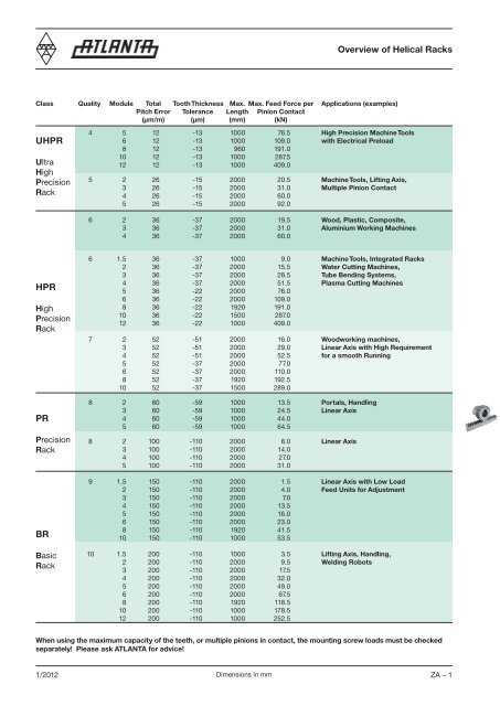
Overview of Helical <strong>Rack</strong>sClass Quality Module Total Tooth Thickness Max. Max. Feed Force per Applications (examples)Pitch Error Tolerance Length Pinion Contact(µm/m) (µm) (mm) (kN)UHPRUltraHighPrecision<strong>Rack</strong>4 5 12 -13 1000 76.5 High Precision Machine Tools6 12 -13 1000 109.0 with Electrical Preload8 12 -13 960 191.010 12 -13 1000 287.512 12 -13 1000 409.05 2 26 -15 2000 20.5 Machine Tools, Lifting Axis,3 26 -15 2000 31.0 Multiple Pinion Contact4 26 -15 2000 60.05 26 -15 2000 92.06 2 36 -37 2000 19.5 Wood, Plastic, Composite,3 36 -37 2000 31.0 Aluminium Working Machines4 36 -37 2000 60.0HPRHighPrecision<strong>Rack</strong>PRPrecision<strong>Rack</strong>BRBasic<strong>Rack</strong>6 1.5 36 -37 1000 9.0 Machine Tools, Integrated <strong>Rack</strong>s2 36 -37 2000 15.5 Water Cutting Machines,3 36 -37 2000 28.5 Tube Bending <strong>Systems</strong>,4 36 -37 2000 51.5 Plasma Cutting Machines5 36 -22 2000 76.06 36 -22 2000 109.08 36 -22 1920 191.010 36 -22 1500 287.012 36 -22 1000 409.07 2 52 -51 2000 16.0 Woodworking machines,3 52 -51 2000 29.0 Linear Axis with High Requirement4 52 -51 2000 52.5 for a smooth Running5 52 -37 2000 77.06 52 -37 2000 110.08 52 -37 1920 192.510 52 -37 1500 289.08 2 60 -59 1000 13.5 Portals, Handling3 60 -59 1000 24.5 Linear Axis4 60 -59 1000 44.05 60 -59 1000 64.58 2 100 -110 2000 8.0 Linear Axis3 100 -110 2000 14.04 100 -110 2000 27.05 100 -110 2000 31.09 1.5 150 -110 2000 1.5 Linear Axis with Low Load2 150 -110 2000 4.0 Feed Units for Adjustment3 150 -110 2000 7.04 150 -110 2000 13.55 150 -110 2000 16.06 150 -110 2000 23.08 150 -110 1920 41.510 150 -110 1000 53.510 1.5 200 -110 1000 3.5 Lifting Axis, Handling,2 200 -110 2000 9.5 Welding Robots3 200 -110 2000 17.54 200 -110 2000 32.05 200 -110 2000 49.06 200 -110 2000 67.58 200 -110 1920 118.510 200 -110 1000 178.512 200 -110 1000 252.5When using the maximum capacity of the teeth, or multiple pinions in contact, the mounting screw loads must be checkedseparately! Please ask <strong>ATLANTA</strong> for advice!1/2012Dimensions in mm ZA – 1
Overview of Helical 1) <strong>Rack</strong>sHeat-Treatment ToleranceClass Series Module of Teethof TeethPageUHPR48 .. ... 5, 6, 8, 10, 12 Induction-Hardened 4 ZA-429 .. ... 2, 3, 4, 5, 6 Case-Hardened 5 ZA-529 .. ... 2, 3, 4 Case-Hardened 6 h ZA-6HPR29 .. ... 1.5, 2, 3, 4, 5, 6, 8, 10, 12 Induction-Hardened 6 h ZA-729 .. ... 2, 3, 4, 5, 6, 8, 10 Induction-Hardened 7 h ZA-839 .. ... 2, 3, 4, 5 Induction-Hardened 8 h ZA-9PRBR38 .. ... 2, 3, 4, 5 Quenched and 8 e 27 ZA-10Tempered47 .. ... 1.5, 2, 3, 4, 5, 6, 8, 10 Soft 9 e 27 ZA-1139 .. ... 1.5, 2, 3, 4, 5, 6, 8, 10, 12 Induction-Hardened 10 e 27 ZA-12–13Selection and Load TablesZA-30–38Electronically Controlled Lubricators, Sliding-Type Lubricating Brushes and Hose-Connection Sets ZE-2 – 6Felt Gear and Mounting Shaft ZE-7 – 8MountingZF-91) All our helical racks are right hand, except the companion racks, which are left hand!ZA – 2 Dimensions in mm1/2012
UHPR <strong>Rack</strong>s Module 5 – 12Quality 4Order N° N°Code Module L 1 L 20 0of Teeth b h k - 0.018 h 0 - 0.018 f a I of Holes h d 1 d 2 t a 1 I 1 d 348 50 105 5 1000.00 17.38 60 49 39 34 2.5 62.5 125 8 12 13.5 20 13 37.5 925 11.7 12.1548 60 105 6 1000.00 20.93 50 59 49 43 2.5 62.5 125 8 16 17.5 26 17 37.5 925 15.7 18.1048 80 105 8 960.00 28.00 36 79 79 71 2.5 60.0 120 8 25 22.0 33 21 120.0 720 19.7 42.5048 10 105 10 1000.00 35.11 30 99 99 89 2.5 62.5 125 8 32 33.0 48 32 125.0 750 19.7 68.7048 12 105 12 1000.00 42.56 25 120 120 108 2.5 40.0 125 8 40 39.0 58 38 102.5 750 19.7 111.00Total pitch error GT f /1000 ≤ 0.012 mm.• Teeth induction-hardened and ground• Material C45• Ground on all sides after hardening• Signed with effective total pitch error (20 °C)Inspection measurement data available as an option.Mounting racks, see page ZF-2.To achieve precision rack joints, we recommend our patented rack assembly kit, see page ZF-4.For lubrication of racks & pinions, we recommend our automatic lubrication systems, see page ZE-1.For the calculation and selection of the rack & pinion drive, see page ZD-1.Screws for rack mounting, see page ZF-3.ZA – 4 Dimensions in mm1/2012
UHPR StrongLine <strong>Rack</strong>s Module 2 – 6Quality 5 StrongLineOrder N° N°Code Module L 1 L 2 of Teeth b h k h 0 f a I of Holes h d 1 d 2 t a 1 I 1 d 329 25 100 2 1000.00 8.5 150 24 24 22 2.0 62.5 125 8 9 10 15.0 9 32.5 935 9.7 4.129 25 150 2 1500.00 8.5 225 24 24 22 2.0 62.5 125 12 9 10 15.0 9 32.5 1435 9.7 6.229 25 200 2 2000.00 8.5 300 24 24 22 2.0 62.5 125 16 9 10 15.0 9 32.5 1935 9.7 8.229 35 100 3 1000.00 10.3 100 29 29 26 2.0 62.5 125 8 10 12 17.5 11 27.5 945 11.7 5.929 35 150 3 1500.00 10.3 150 29 29 26 2.0 62.5 125 12 10 12 17.5 11 27.5 1445 11.7 8.929 35 200 3 2000.00 10.3 200 29 29 26 2.0 62.5 125 16 10 12 17.5 11 27.5 1945 11.7 11.829 45 100 4 1000.00 13.8 75 39 39 35 2.0 62.5 125 8 13 16 23.0 15 30.0 940 15.7 10.729 45 150 1) 4 1506.67 13.8 113 39 39 35 2.0 62.5 125 12 13 16 23.0 15 30.0 1440 15.7 15.829 45 200 4 2000.00 13.8 150 39 39 35 2.0 62.5 125 16 13 16 23.0 15 30.0 1940 15.7 21.429 55 100 5 1000.00 17.4 60 49 49 44 2.5 62.5 125 8 15 18 26.0 17 34.5 931 15.7 16.329 55 150 5 1500.00 17.4 90 49 49 44 2.5 62.5 125 12 15 18 26.0 17 34.5 1431 15.7 25.329 55 200 5 2000.00 17.4 120 49 49 44 2.5 62.5 125 16 15 18 26.0 17 34.5 1931 15.7 32.629 65 100 6 1000.00 20.9 50 59 59 53 2.5 62.5 125 8 20 22 33.0 21 97.5 805 19.7 24.529 65 150 6 1500.00 20.9 75 59 59 53 2.5 62.5 125 12 20 22 33.0 21 97.5 1305 19.7 36.829 65 200 6 2000.00 20.9 100 59 59 53 2.5 62.5 125 16 20 22 33.0 21 97.5 1805 19.7 49.11) These racks should be used for continuous linking only with the left side (see sketch).Total pitch error:GT f /1000 ≤ 0.026 mmGT f /1500 ≤ 0.031 mm (≤ 0.021/1000 mm)GT f /2000 ≤ 0.034 mm (≤ 0.017/1000 mm)• Case hardened and teeth ground• Material 16MnCr5• Ground on all sides after hardening• Signed with effective total pitch error (20 °C)Inspection measurement data available as an option.Mounting racks, see page ZF-2.To achieve precision rack joints, we recommend our patented rack assembly kit, see page ZF-4.For lubrication of racks & pinions, we recommend our automatic lubrication systems, see page ZE-1.For the calculation and selection of the rack & pinion drive, see page ZD-1.Screws for rack mounting, see page ZF-3.1/2012Dimensions in mm ZA – 5
HPR <strong>Rack</strong>s Module 2 – 4Quality 6Order N° N°Code Module L 1 L 2 of Teeth b h k h 0 f a I of Holes h d 1 d 2 t a 1 I 1 d 329 20 050 2) 2 500.00 8.5 75 24 24 22 2 62.5 125 4 8 7 11 7 31.7 436.6 5.7 2.1029 21 050 2 500.00 8.5 75 24 24 22 2 without Mounting Holes 2.1029 20 100 2 1000.00 8.5 150 24 24 22 2 62.5 125 8 8 7 11 7 31.7 936.6 5.7 4.1029 21 100 2 1000.00 8.5 150 24 24 22 2 without Mounting Holes 4.1029 20 150 2 1500.00 8.5 225 24 24 22 2 62.5 125 12 8 7 11 7 31.7 1436.6 5.7 6.1529 21 150 2 1500.00 8.5 225 24 24 22 2 without Mounting Holes 6.1529 20 200 2 2000.00 8.5 300 24 24 22 2 62.5 125 16 8 7 11 7 31.7 1936.6 5.7 8.2029 21 200 2 2000.00 8.5 300 24 24 22 2 without Mounting Holes 8.2029 30 050 2) 3 500.00 10.3 50 29 29 26 2 62.5 125 4 9 10 15 9 35.0 430.0 7.7 2.9029 31 050 3 500.00 10.3 50 29 29 26 2 without Mounting Holes 2.9029 30 100 3 1000.00 10.3 100 29 29 26 2 62.5 125 8 9 10 15 9 35.0 930.0 7.7 5.9029 31 100 3 1000.00 10.3 100 29 29 26 2 without Mounting Holes 5.9029 30 150 3 1500.00 10.3 150 29 29 26 2 62.5 125 12 9 10 15 9 35.0 1430.0 7.7 8.8529 31 150 3 1500.00 10.3 150 29 29 26 2 without Mounting Holes 8.8529 30 200 3 2000.00 10.3 200 29 29 26 2 62.5 125 16 9 10 15 9 35.0 1930.0 7.7 11.8029 31 200 3 2000.00 10.3 200 29 29 26 2 without Mounting Holes 11.8029 40 050 1) 2) 4 506.67 13.8 38 39 39 35 2 62.5 125 4 12 10 15 9 33.3 433.0 7.7 5.4029 41 050 4 506.67 13.8 38 39 39 35 2 without Mounting Holes 5.4029 40 100 2) 4 1000.00 13.8 75 39 39 35 2 62.5 125 8 12 10 15 9 33.3 933.4 7.7 10.7029 41 100 4 1000.00 13.8 75 39 39 35 2 without Mounting Holes 10.7029 42 100 4 1000.00 13.8 75 39 39 35 2 62.5 125 8 12 14 20 13 33.3 933.4 11.7 10.7029 41 150 4 1506.67 13.8 113 39 39 35 2 without Mounting Holes 16.0029 42 150 1) 4 1506.67 13.8 113 39 39 35 2 62.5 125 12 12 14 20 13 33.3 1433.4 11.7 16.0029 41 200 4 2000.00 13.8 150 39 39 35 2 without Mounting Holes 21.4029 42 200 4 2000.00 13.8 150 39 39 35 2 62.5 125 16 12 14 20 13 33.3 1933.4 11.7 21.401) This racks should be used for continuous linking only with the left side (see sketch).2) The screw joint limits the feed force.Total pitch error:GT f /1000 ≤ 0.036 mmGT f /1500 ≤ 0.043 mm (≤ 0.029/1000 mm)GT f /2000 ≤ 0.047 mm (≤ 0.024/1000 mm)• Teeth induction-hardened and ground• Material 16MnCr5, carburized• Ground on all sides after hardeningMounting racks, see page ZF-2.To achieve precision rack joints, we recommend our patented rack assembly kit, see page ZF-4.For lubrication of racks & pinions, we recommend our automatic lubrication systems, see page ZE-1.For the calculation and selection of the rack & pinion drive, see page ZD-1.Screws for rack mounting, see page ZF-3.ZA – 6 Dimensions in mm1/2012
HPR <strong>Rack</strong>s Module 1.5 – 12Quality 6Order N° N°Code Module L 1 L 2 of Teeth b h k h 0 f a I of Holes h d 1 d 2 t a 1 I 1 d 329 15 055 2) 1.5 500.00 6.74 100 19 19 17.5 2 62.5 125 4 8 7 11 7 31.7 436.6 5.7 1.3029 16 055 1.5 500.00 6.74 100 19 19 17.5 2 without Mounting Holes 1.3029 15 105 1.5 1000.00 6.74 200 19 19 17.5 2 62.5 125 8 8 7 11 7 31.7 936.6 5.7 2.6029 16 105 1.5 1000.00 6.74 200 19 19 17.5 2 without Mounting Holes 2.6029 20 105 2 1000.00 8.50 150 24 24 22 2 62.5 125 8 8 7 11 7 31.7 936.6 5.7 4.1029 21 105 2 1000.00 8.50 150 24 24 22 2 without Mounting Holes 4.1029 20 155 2 1500.00 8.50 225 24 24 22 2 62.5 125 12 8 7 11 7 31.7 1436.6 5.7 6.1529 21 155 2 1500.00 8.50 225 24 24 22 2 without Mounting Holes 6.1529 20 205 2 2000.00 8.50 300 24 24 22 2 62.5 125 16 8 7 11 7 31.7 1936.6 5.7 8.2029 21 205 2 2000.00 8.50 300 24 24 22 2 without Mounting Holes 8.2029 30 105 3 1000.00 10.30 100 29 29 26 2 62.5 125 8 9 10 15 9 35.0 930.0 7.7 5.9029 31 105 3 1000.00 10.30 100 29 29 26 2 without Mounting Holes 5.9029 30 155 3 1500.00 10.30 150 29 29 26 2 62.5 125 12 9 10 15 9 35.0 1430.0 7.7 8.8529 31 155 3 1500.00 10.30 150 29 29 26 2 without Mounting Holes 8.8529 30 205 3 2000.00 10.30 200 29 29 26 2 62.5 125 16 9 10 15 9 35.0 1930.0 7.7 11.8029 31 205 3 2000.00 10.30 200 29 29 26 2 without Mounting Holes 11.8029 40 105 2) 4 1000.00 13.80 75 39 39 35 2 62.5 125 8 12 10 15 9 33.3 933.4 7.7 10.7029 41 105 4 1000.00 13.80 75 39 39 35 2 without Mounting Holes 10.7029 42 105 4 1000.00 13.80 75 39 39 35 2 62.5 125 8 12 14 20 13 33.3 939.4 11.7 13.0029 42 155 1) 4 1506.67 13.80 113 39 39 35 2 62.5 125 12 12 14 20 13 33.3 1433.4 11.7 19.5029 40 205 4 2000.00 13.80 150 39 39 35 2 62.5 125 16 12 10 15 9 33.3 1933.4 7.7 21.4029 41 205 4 2000.00 13.80 150 39 39 35 2 without Mounting Holes 21.4029 42 205 4 2000.00 13.80 150 39 39 35 2 62.5 125 16 12 14 20 13 33.3 1933.4 11.7 21.4029 50 055 2) 5 500.00 17.40 30 49 39 34 2.5 62.5 125 4 12 14 20 13 37.5 425.0 11.7 6.5029 51 055 5 500.00 17.40 30 49 39 34 2.5 without Mounting Holes 6.5029 50 105 5 1000.00 17.40 60 49 39 34 2.5 62.5 125 8 12 14 20 13 37.5 925.0 11.7 13.0029 51 105 5 1000.00 17.40 60 49 39 34 2.5 without Mounting Holes 13.0029 50 155 5 1500.00 17.40 90 49 39 34 2.5 62.5 125 12 12 14 20 13 37.5 1425.0 11.7 19.5029 51 155 5 1500.00 17.40 90 49 39 34 2.5 without Mounting Holes 19.5029 50 205 5 2000.00 17.40 120 49 39 34 2.5 62.5 125 16 12 14 20 13 37.5 1925.0 11.7 26.0029 51 205 5 2000.00 17.40 120 49 39 34 2.5 without Mounting Holes 26.0029 60 055 2) 6 500.00 20.90 25 59 49 43 2.5 62.5 125 4 16 18 26 17 37.5 425.0 15.7 9.9029 61 055 6 500.00 20.90 25 59 49 43 2.5 without Mounting Holes 9.9029 60 105 6 1000.00 20.90 50 59 49 43 2.5 62.5 125 8 16 18 26 17 37.5 925.0 15.7 18.1029 61 105 6 1000.00 20.90 50 59 49 43 2.5 without Mounting Holes 18.1029 60 155 6 1500.00 20.90 75 59 49 43 2.5 62.5 125 12 16 18 26 17 37.5 1425.0 15.7 27.1029 61 155 6 1500.00 20.90 75 59 49 43 2.5 without Mounting Holes 27.1029 60 205 6 2000.00 20.90 100 59 49 43 2.5 62.5 125 16 16 18 26 17 37.5 1925.0 15.7 36.2029 61 205 6 2000.00 20.90 100 59 49 43 2.5 without Mounting Holes 36.2029 80 055 2) 8 480.00 28.00 18 79 79 71 2.5 60.0 120 4 25 22 33 21 120.0 240.0 19.7 21.0029 81 055 8 480.00 28.00 18 79 79 71 2.5 without Mounting Holes 21.0029 80 105 8 960.00 28.00 36 79 79 71 2.5 60.0 120 8 25 22 33 21 120.0 720.0 19.7 42.5029 81 105 8 960.00 28.00 36 79 79 71 2.5 without Mounting Holes 42.5029 80 205 8 1920.00 28.00 72 79 79 71 2.5 60.0 120 16 25 22 33 21 120.0 1680.0 19.7 85.0029 81 205 8 1920.00 28.00 72 79 79 71 2.5 without Mounting Holes 85.0029 10 105 10 1000.00 35.11 30 99 99 89 2.5 62.5 125 8 32 33 48 32 125.0 750.0 19.7 68.7229 11 105 10 1000.00 35.11 30 99 99 89 2.5 without Mounting Holes 68.7229 10 155 10 1500.00 35.11 45 99 99 89 2.5 62.5 125 12 32 33 48 32 125 1250.0 19.7 103.0029 11 155 10 1500.00 35.11 45 99 99 89 2.5 without Mounting Holes 103.0029 12 105 12 1000.00 42.56 25 120 120 108 2.5 40.0 125 8 40 39 58 38 125.0 750.0 19.7 111.0029 13 105 12 1000.00 42.56 25 120 120 108 2.5 without Mounting Holes 111.001) These racks should be used for continuous linking only with the left side (see sketch).2) The screw joint limits the feed force.Total pitch error: GT f /1000 ≤ 0.036 mm, GT f /1500 ≤ 0.043 mm (≤ 0.029/1000 mm)GT f /2000 ≤ 0.047 mm (≤ 0.024/1000 mm)• Further information see next page.1/2012Dimensions in mm ZA – 7
HPR <strong>Rack</strong>s Module 2 – 10Quality 7Order N° N°Code Module L 1 L 2 of Teeth b h k h 0 f a I of Holes h d 1 d 2 t a 1 I 1 d 329 20 107 2 1000.00 8.5 150 24 24 22 2 62.5 125 8 8 7 11 7 31.7 936.6 5.7 4.1029 20 157 2 1500.00 8.5 225 24 24 22 2 62.5 125 12 8 7 11 7 31.7 1436.6 5.7 6.1529 20 207 2 2000.00 8.5 300 24 24 22 2 62.5 125 16 8 7 11 7 31.7 1936.6 5.7 8.2029 30 107 3 1000.00 10.3 100 29 29 26 2 62.5 125 8 9 10 15 9 35.0 930.0 7.7 5.9029 30 157 3 1500.00 10.3 150 29 29 26 2 62.5 125 12 9 10 15 9 35.0 1430.0 7.7 8.8529 30 207 3 2000.00 10.3 200 29 29 26 2 62.5 125 16 9 10 15 9 35.0 1930.0 7.7 11.8029 40 107 4 1000.00 13.8 75 39 39 35 2 62.5 125 8 12 14 20 13 33.3 933.4 11.7 10.7029 40 157 1) 4 1506.67 13.8 113 39 39 35 2 62.5 125 12 12 14 20 13 33.3 1433.4 11.7 16.0029 40 207 4 2000.00 13.8 150 39 39 35 2 62.5 125 16 12 14 20 13 33.3 1933.4 11.7 21.4029 50 107 5 1000.00 17.4 60 49 39 34 2.5 62.5 125 8 12 14 20 13 37.5 925.0 11.7 13.0029 50 157 5 1500.00 17.4 90 49 39 34 2.5 62.5 125 12 12 14 20 13 37.5 1425.0 11.7 19.5029 50 207 5 2000.00 17.4 120 49 39 34 2.5 62.5 125 16 12 14 20 13 37.5 1925.0 11.7 26.0029 60 107 6 1000.00 20.9 50 59 49 43 2.5 62.5 125 8 16 18 26 17 37.5 925.0 15.7 18.1029 60 157 6 1500.00 20.9 75 59 49 43 2.5 62.5 125 12 16 18 26 17 37.5 1425.0 15.7 27.1029 60 207 6 2000.00 20.9 100 59 49 43 2.5 62.5 125 16 16 18 26 17 37.5 1925.0 15.7 36.2029 80 107 8 960.00 28.0 36 79 79 71 2.5 60.0 120 8 25 22 33 21 120.0 720.0 19.7 42.5029 80 157 8 1440.00 28.0 54 79 79 71 2.5 60.0 120 12 25 22 33 21 120.0 1200.0 19.7 65.0029 80 207 8 1920.00 28.0 72 79 79 71 2.5 60.0 120 16 25 22 33 21 120.0 1680.0 19.7 85.0029 10 107 10 1000.00 35.11 30 99 99 89 2.5 62.5 125 8 32 33 48 32 125.0 750.0 19.7 68.7229 10 157 10 1500.00 35.11 45 99 99 89 2.5 62.5 125 12 32 33 48 32 125.0 1425.0 19.7 104.001) These racks should be used for continuous linking only with the left side (see sketch).Total pitch error:GT f /1000 ≤ 0.052 mmGT f /1500 ≤ 0.062 mm (≤ 0.041/1000 mm)GT f /2000 ≤ 0.068 mm (≤ 0.034/1000 mm)• Teeth induction-hardened and ground• Material C45• Ground on all sides after hardeningMounting racks, see page ZF-2.To achieve precision rack joints, we recommend our patented rack assembly kit, see page ZF-4.For lubrication of racks & pinions, we recommend our automatic lubrication systems, see page ZE-1.For the calculation and selection of the rack & pinion drive, see page ZD-1.Screws for rack mounting, see page ZF-3.ZA – 8 Dimensions in mm1/2012
PR <strong>Rack</strong>s Module 2 – 5Quality 8Order N° N°Code Module L 1 L 2 of Teeth b h k h 0 f a I of Holes h d 1 d 2 t a 1 I 1 d 339 20 108 2 1000.00 8.5 150 25 24 22 2 62.5 125 8 8 7 11 7 31.7 936.6 5.7 4.1039 30 108 3 1000.00 10.3 100 30 29 26 2 62.5 125 8 9 10 15 9 35.0 930.0 7.7 5.9039 40 108 4 1000.00 13.8 75 40 39 35 2 62.5 125 8 12 14 20 13 33.3 933.4 11.7 10.7039 50 108 5 1000.00 17.4 60 50 39 34 2.5 62.5 125 8 12 14 20 13 37.5 925.0 11.7 13.00Total pitch error GT f /1000 ≤ 0.060 mm.• Teeth induction-hardened and ground• Material C45• Bright steel, profile blastedMounting racks, see page ZF-2.To achieve precision rack joints, we recommend our patented rack assembly kit, see page ZF-4.For lubrication of racks & pinions, we recommend our automatic lubrication systems, see page ZE-1.For the calculation and selection of the rack & pinion drive, see page ZD-1.Screws for rack mounting, see page ZF-3.1/2012Dimensions in mm ZA – 9
PR <strong>Rack</strong>s Module 2 – 5Quality 8Order N° N°Code Module L 1 L 2 of Teeth b h k h 0 f a I of Holes h d 1 d 2 t a 1 I 1 d 338 21 050 2 500.00 8.9 75 25 24 22 2 62.5 125 4 8 7 11 7 31.7 436.6 5.7 2.1038 20 050 2 500.00 8.9 75 25 24 22 2 without Mounting Holes 2.1038 21 100 2 1000.00 8.9 150 25 24 22 2 62.5 125 8 8 7 11 7 31.7 936.6 5.7 4.3038 20 100 2 1000.00 8.9 150 25 24 22 2 without Mounting Holes 4.3038 21 200 2 2000.00 8.9 300 25 24 22 2 62.5 125 16 8 7 11 7 31.7 1936.6 5.7 8.6038 20 200 2 2000.00 8.9 300 25 24 22 2 without Mounting Holes 8.6038 31 050 3 500.00 10.6 50 30 29 26 2 62.5 125 4 9 10 15 9 35.0 430.0 7.7 3.0038 30 050 3 500.00 10.6 50 30 29 26 2 without Mounting Holes 3.0038 31 100 3 1000.00 10.6 100 30 29 26 2 62.5 125 8 9 10 15 9 35.0 930.0 7.7 6.1038 30 100 3 1000.00 10.6 100 30 29 26 2 without Mounting Holes 6.1038 31 200 3 2000.00 10.6 200 30 29 26 2 62.5 125 16 9 10 15 9 35.0 1930.0 7.7 12.2038 30 200 3 2000.00 10.6 200 30 29 26 2 without Mounting Holes 12.2038 41 050 1.2) 4 506.67 14.2 38 40 39 35 2 62.5 125 4 12 10 15 9 33.3 433.0 7.7 5.5038 40 050 4 506.67 14.2 38 40 39 35 2 without Mounting Holes 5.5038 41 100 4 1000.00 14.2 75 40 39 35 2 62.5 125 8 12 10 15 9 33.3 933.4 7.7 10.9038 40 100 4 1000.00 14.2 75 40 39 35 2 without Mounting Holes 10.9038 41 200 4 2000.00 14.2 150 40 39 35 2 62.5 125 16 12 10 15 9 33.3 1933.4 7.7 21.8038 40 200 4 2000.00 14.2 150 40 39 35 2 without Mounting Holes 21.8038 51 050 5 500.00 17.4 30 50 39 34 2.5 62.5 125 4 12 14 20 13 37.5 425.0 11.7 6.5038 50 050 5 500.00 17.4 30 50 39 34 2.5 without Mounting Holes 6.5038 51 100 5 1000.00 17.4 60 50 39 34 2.5 62.5 125 8 12 14 20 13 37.5 925.0 11.7 13.0038 50 100 5 1000.00 17.4 60 50 39 34 2.5 without Mounting Holes 13.0038 51 200 5 2000.00 17.4 120 50 39 34 2.5 62.5 125 16 12 14 20 13 37.5 1925.0 11.7 26.0038 50 200 5 2000.00 17.4 120 50 39 34 2.5 without Mounting Holes 26.001) These racks should be used for continuous linking only with the left side (see sketch).2) The screw joint limits the feed force.Total pitch error GT f /1000 ≤ 0.100 mm.• Milled teeth• Material 42CrMo4, quenched and tempered• Bright steel, backside machinedMounting racks, see page ZF-2.To achieve precision rack joints, we recommend our patented rack assembly kit, see page ZF-4.For lubrication of racks & pinions, we recommend our automatic lubrication systems, see page ZE-1.For the calculation and selection of the rack & pinion drive, see page ZD-1.Screws for rack mounting, see page ZF-3.ZA – 10 Dimensions in mm1/2012
BR <strong>Rack</strong>s Module 1.5 – 6Quality 10Order N° N°Code Module L 1 L 2 of Teeth b h k h 0 f a I of Holes h d 1 d 2 t a 1 I 1 d 339 15 050 2) 1.5 500.00 6.02 100 17 17 15.5 2 62.5 125 4 6 6 10 6 31.7 436.6 5.7 1.3039 16 050 1.5 500.00 6.02 100 17 17 15.5 2 without Mounting Holes 1.3039 15 100 1.5 1000.00 6.02 200 17 17 15.5 2 62.5 125 8 6 6 10 6 31.7 936.6 5.7 2.6039 16 100 1.5 1000.00 6.02 200 17 17 15.5 2 without Mounting Holes 2.6039 20 050 2) 2 500.00 8.87 75 25 24 22 2 62.5 125 4 8 7 11 7 31.7 436.6 5.7 2.1039 21 050 2 500.00 8.87 75 25 24 22 2 without Mounting Holes 2.1039 20 100 2 1000.00 8.87 150 25 24 22 2 62.5 125 8 8 7 11 7 31.7 936.6 5.7 4.2039 21 100 2 1000.00 8.87 150 25 24 22 2 without Mounting Holes 4.2039 20 200 2 2000.00 8.87 300 25 24 22 2 62.5 125 16 8 7 11 7 31.7 1936.6 5.7 8.4039 21 200 2 2000.00 8.87 300 25 24 22 2 without Mounting Holes 8.4039 30 050 2) 3 500.00 10.64 50 30 29 26 2 62.5 125 4 9 10 15 9 35.0 430.0 7.7 3.0039 31 050 3 500.00 10.64 50 30 29 26 2 without Mounting Holes 3.0039 30 100 3 1000.00 10.64 100 30 29 26 2 62.5 125 8 9 10 15 9 35.0 930.0 7.7 6.0039 31 100 3 1000.00 10.64 100 30 29 26 2 without Mounting Holes 6.0039 30 200 3 2000.00 10.64 200 30 29 26 2 62.5 125 16 9 10 15 9 35.0 1930.0 7.7 12.0039 31 200 3 2000.00 10.64 200 30 29 26 2 without Mounting Holes 12.0039 40 050 1) 2) 4 506.67 14.2 38 40 39 35 2 62.5 125 4 12 10 15 9 33.3 433.0 7.7 5.3039 41 050 4 506.67 14.2 38 40 39 35 2 without Mounting Holes 5.3039 40 100 2) 4 1000.00 14.2 75 40 39 35 2 62.5 125 8 12 10 15 9 33.3 933.4 7.7 10.5039 41 100 4 1000.00 14.2 75 40 39 35 2 without Mounting Holes 10.5039 42 100 4 1000.00 14.2 75 40 39 35 2 62.5 125 8 12 14 20 13 33.3 933.4 11.7 10.5039 42 150 1) 4 1506.67 14.2 113 40 39 35 2 62.5 125 12 12 14 20 13 33.3 1433.4 11.7 15.7539 40 200 4 2000.00 14.2 150 40 39 35 2 62.5 125 16 12 10 15 9 33.3 1933.4 7.7 21.0039 41 200 4 2000.00 14.2 150 40 39 35 2 without Mounting Holes 21.0039 42 200 4 2000.00 14.2 150 40 39 35 2 62.5 125 16 12 14 20 13 33.3 1933.4 11.7 21.0039 50 050 2) 5 500.00 17.7 30 50 39 34 2.5 62.5 125 4 12 14 20 13 37.5 425.0 11.7 6.5039 51 050 5 500.00 17.7 30 50 39 34 2.5 without Mounting Holes 6.5039 50 100 5 1000.00 17.7 60 50 39 34 2.5 62.5 125 8 12 14 20 13 37.5 925.0 11.7 13.0039 51 100 5 1000.00 17.7 60 50 39 34 2.5 without Mounting Holes 13.0039 50 200 5 2000.00 17.7 120 50 39 34 2.5 62.5 125 16 12 14 20 13 37.5 1925.0 11.7 26.0039 51 200 5 2000.00 17.7 120 50 39 34 2.5 without Mounting Holes 26.0039 60 050 2) 6 500.00 21.4 25 60 49 43 2.5 62.5 125 4 16 18 26 17 37.5 425.0 15.7 9.9039 61 050 6 500.00 21.4 25 60 49 43 2.5 without Mounting Holes 9.9039 60 100 6 1000.00 21.4 50 60 49 43 2.5 62.5 125 8 16 18 26 17 37.5 925.0 15.7 19.8039 61 100 6 1000.00 21.4 50 60 49 43 2.5 without Mounting Holes 19.8039 60 200 6 2000.00 21.4 100 60 49 43 2.5 62.5 125 16 16 18 26 17 37.5 1925.0 15.7 39.6039 61 200 6 2000.00 21.4 100 60 49 43 2.5 without Mounting Holes 39.601) These racks should be used for continuous linking only with the left side (see sketch).2) The screw joint limits the feed force.Total pitch error GT f /1000 ≤ 0.200 mm.• Milled teeth and induction hardened• Material C45• Backside machined, profile blastedFurther information see page ZA–13.ZA – 12 Dimensions in mm1/2012
BR <strong>Rack</strong>s Module 8 – 12Quality 10Order N° N°Code Module L 1 L 2 of Teeth b h k h 0 f a I of Holes h d 1 d 2 t a 1 I 1 d 339 80 050 2) 8 480.00 28.4 18 80 79 71 2.5 60.0 120 4 25 22 33 21 120.0 240 19.7 21.0039 81 050 8 480.00 28.4 18 80 79 71 2.5 without Mounting Holes 21.0039 80 100 8 960.00 28.4 36 80 79 71 2.5 60.0 120 8 25 22 33 21 120.0 720 19.7 42.5039 81 100 8 960.00 28.4 36 80 79 71 2.5 without Mounting Holes 42.5039 80 200 8 1920.00 28.4 72 80 79 71 2.5 60.0 120 16 25 22 33 21 120.0 1680 19.7 85.0039 81 200 8 1920.00 28.4 72 80 79 71 2.5 without Mounting Holes 85.0039 10 100 10 1000.00 35.46 30 100 99 89 2.5 62.5 125 8 32 33 48 32 125.0 750 19.7 68.7239 11 100 10 1000.00 35.46 30 100 99 89 2.5 without Mounting Holes 68.7239 12 100 12 1000.00 42.56 25 120 120 108 2.5 40.0 125 8 40 39 58 38 102.5 750 19.7 120.0039 13 100 12 1000.00 42.56 25 120 120 108 2.5 without Mounting Holes 120.001) These racks should be used for continuous linking only with the left side (see sketch).2) The screw joint limits the feed force.Total pitch error GT f /1000 ≤ 0.200 mm.• Milled teeth and induction hardened• Material C45• Backside machined, profile blastedMounting racks, see page ZF-2.To achieve precision rack joints, we recommend our patented rack assembly kit, see page ZF-4.For lubrication of racks & pinions, we recommend our automatic lubrication systems, see page ZE-1.For the calculation and selection of the rack & pinion drive, see page ZD-1.Screws for rack mounting, see page ZF-3.1/2012Dimensions in mm ZA – 13
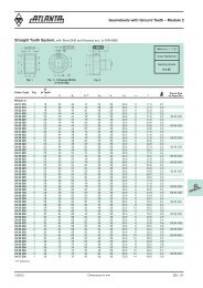
Overview of Straight <strong>Rack</strong>sToothMax. FeedClass Quality Module Total Thickness Max. Force Per Applications (Examples)Pitch Error Tolerance Length Pinion Contact(µm/m) (µm) (mm) (kN)UHPRUltraHighPrecision<strong>Rack</strong>4 5 12 -13 1005 62.0 High Precision Machine Tools6 12 -13 1018 89.0 with Electrical Preload8 12 -13 1005 156.010 12 -13 1005 234.012 12 -13 1018 333.55 2 26 -15 2011 17.0 Backlash Free <strong>Drive</strong>s with Electrical3 26 -15 2036 25.5 Preload, Machine Tools, Lifting Axis,4 26 -15 2011 49.0 Multiple Pinion Contact5 26 -15 2011 75.06 2 36 -37 1005 15.5 Wood, Plastic, Composite,3 36 -37 1018 25.5 Aluminium Working Machines4 36 -37 1005 49.0HPRHighPrecision<strong>Rack</strong>PRPrecision<strong>Rack</strong>BRBasic<strong>Rack</strong>6 2 36 -37 2011 12.5 Machine Tools, Integrated <strong>Rack</strong>s,3 36 -37 2036 23.5 Water Cutting Machines,4 36 -37 2011 42.0 Tube Bending <strong>Systems</strong>,5 36 -22 2011 62.0 Plasma Cutting Machines6 36 -22 2036 89.08 36 -22 2011 155.510 36 -22 1005 234.012 36 -22 1018 333.07 2 52 -51 1005 13.0 Woodworking Machines,3 52 -51 1018 23.5 Linear Axis with High Requirement4 52 -51 1005 42.5 for a Smooth Running5 52 -37 1005 62.56 52 -37 1018 89.08 52 -37 1005 155.58 2 60 -59 1005 12.0 Portals, Handling3 60 -59 1018 22.0 Linear Axis4 60 -59 1005 39.05 60 -59 1005 57.58 2 100 -110 2011 7.0 Linear Axis3 100 -110 2036 12.04 100 -110 2011 23.05 100 -110 2011 27.09 1 150 -110 999 0.7 Linear Axis with Low Load1.5 150 -110 1998 1.0 Feed Units for Adjustment2 150 -110 3016 3.02.5 150 -110 2003 3.03 150 -110 3054 6.54 150 -110 3016 12.55 150 -110 2011 14.56 150 -110 2036 21.58 150 -110 2011 38.510 150 -110 1005 49.510 2 200 -110 2011 7.0 Lifting Axis, Handling,3 200 -110 2036 16.5 Welding Robots4 200 -110 2011 29.55 200 -110 2011 45.56 200 -110 2036 63.010 1 200 -110 999 2.0 Driving and Lifting Axis for Higher Loads1.5 200 -110 1998 3.5 but without Special Accuracy2 200 -110 3016 7.02.5 200 -110 2003 8.53 200 -110 3054 16.54 200 -110 3016 29.55 200 -110 2011 45.56 200 -110 2036 63.08 200 -110 2011 110.010 200 -110 1005 166.0When using the maximum capacity of the teeth, or multiple pinions in contact, the mounting screw loads must be checkedseparately! Please ask <strong>ATLANTA</strong> for advice!1/2012Dimensions in mm ZB – 1
Overview of Straight <strong>Rack</strong>sHeat-Treatment ToleranceClass Series Moduleof Teethof TeethPage46 .. ... 5, 6, 8, 10, 12 Induction-Hardened 4 ZB-4UHPR28 .. ... 2, 3, 4, 5, 6 Case-Hardened 5 ZB-528 .. ... 2, 3, 4 Case-Hardened 6 h ZB-6HPR28 .. ... 2, 3, 4, 5, 6, 8, 10, 12 Induction-Hardened 6 h ZB-728 .. ... 2, 3, 4, 5, 6, 8 Induction-Hardened 7 h ZB-8PR34 .. ... 2, 3, 4, 5 Induction-Hardened 8 h ZB-933 .. ... 2, 3, 4, 5 Quenched and 8 e 27 ZB-10Tempered25 .. ... 1, 1.5, 2, 2.5, 3, 4, 5, 6, 8, 10 Soft 9 e 27 ZB-11–12BR27 .. ... 1, 1.5, 2, 2.5, 3, 4, 5, 6, 8, 10 Induction-Hardened 10 e 27 ZB-13 – 1434 .. ... 2, 3, 4, 5, 6 Induction-Hardened 10 e 27 ZB-15Selection and Load Tables ZB-36 – 46Electronically Controlled Lubricators, Sliding-Type Lubricating Brushes and Hose-Connection Sets ZE-2 – 6Felt Gear and Mounting Shaft ZE-7 – 8MountingZF-9ZB – 2 Dimensions in mm1/2012
UHPR <strong>Rack</strong>s Module 5 – 12Quality 4Order N° N°Code Module L 1 of Teeth b0 0h k - 0.018 h 0 - 0.018 f a I of Holes h d 1 d 2 t a 1 I 1 d 346 50 105 5 1005.3 64 49 39 34 2.5 62.8 125.66 8 12 13.5 20 13 30.10 945.0 11.7 12.246 60 105 6 1017.9 54 59 49 43 2.5 63.6 127.23 8 16 17.5 26 17 31.40 955.0 15.7 18.546 80 105 8 1005.3 40 79 79 71 2.5 62.8 125.66 8 25 22.0 33 21 26.60 952.0 19.7 22.046 10 105 10 1005.3 32 99 99 89 2.5 62.8 125.66 8 32 33.0 48 32 125.66 753.9 19.7 68.046 12 105 12 1017.9 27 120 120 108 2.5 63.6 127.23 8 40 39.0 58 38 127.23 763.4 19.7 111.0Total pitch error GT f /1000 ≤ 0.012 mm.• Teeth induction-hardened and ground• Material C45• Ground on all sides after hardening• Signed with effective total pitch error (20 °C)Inspection measurement data available as an option.Mounting racks, see page ZF-2.To achieve precision rack joints, we recommend our patented rack assembly kit, see page ZF-4.For lubrication of rack & pinions we recommend our automatic lubrication systems, see page ZE-1.For the calculation and selection of the rack & pinion drive, see page ZD-1.Screws for rack mounting, see page ZF-3.ZB – 4 Dimensions in mm1/2012
UHPR StrongLine <strong>Rack</strong>s Module 2 – 6Quality 5 StrongLineOrder N° N°Code Module L 1 of Teeth b h k h 0 f a I of Holes h d 1 d 2 t a 1 I 1 d 328 25 100 2 1005.31 160 24 24 22 2.0 62.83 125.66 8 9 10 15.0 9 32.8 939.7 9.7 4.128 25 150 2 1507.96 240 24 24 22 2.0 62.83 125.66 12 9 10 15.0 9 32.8 1442.3 9.7 6.228 25 200 2 2010.62 320 24 24 22 2.0 62.83 125.66 16 9 10 15.0 9 32.8 1945.0 9.7 8.228 35 100 3 1017.88 108 29 29 26 2.0 63.61 127.23 8 10 12 17.5 11 28.6 960.6 11.7 5.928 35 150 3 1526.81 162 29 29 26 2.0 63.61 127.23 12 10 12 17.5 11 28.6 1469.6 11.7 8.928 35 200 3 2035.75 216 29 29 26 2.0 63.61 127.23 16 10 12 17.5 11 28.6 1978.5 11.7 11.828 45 100 4 1005.31 80 39 39 35 2.0 62.83 125.66 8 13 16 23.0 15 30.3 944.7 15.7 10.728 45 150 4 1507.96 120 39 39 35 2.0 62.83 125.66 12 13 16 23.0 15 30.3 1447.3 15.7 15.828 45 200 4 2010.62 160 39 39 35 2.0 62.83 125.66 16 13 16 23.0 15 30.3 1950.0 15.7 21.428 55 100 5 1005.31 64 49 49 44 2.5 62.83 125.66 8 15 18 26.0 17 34.8 935.7 15.7 16.328 55 150 5 1507.96 96 49 49 44 2.5 62.83 125.66 12 15 18 26.0 17 34.8 1438.3 15.7 25.328 55 200 5 2010.62 128 49 49 44 2.5 62.83 125.66 16 15 18 26.0 17 34.8 1941.0 15.7 32.628 65 100 6 1017.88 54 59 59 53 2.5 63.62 127.23 8 20 22 33.0 21 28.6 960.6 19.7 24.528 65 150 6 1526.81 81 59 59 53 2.5 63.62 127.23 12 20 22 33.0 21 28.6 1469.6 19.7 36.828 65 200 6 2035.75 108 59 59 53 2.5 63.62 127.23 16 20 22 33.0 21 28.6 1978.5 19.7 49.1Total pitch error:GT f /1000 ≤ 0.026 mmGT f /1500 ≤ 0.031 mm (≤ 0.021/1000 mm)GT f /2000 ≤ 0.034 mm (≤ 0.017/1000 mm)• Case hardened and teeth ground• Material 16MnCr5• Ground on all sides after hardening• Signed with effective total pitch error (20 °C)Inspection measurement data available as an option.Mounting racks, see page ZF-2.To achieve precision rack joints, we recommend our patented rack assembly kit, see page ZF-4.For lubrication of rack & pinions we recommend our automatic lubrication systems, see page ZE-1.For the calculation and selection of the rack & pinion drive, see page ZD-1.Screws for rack mounting, see page ZF-3.1/2012Dimensions in mm ZB – 5
HPR <strong>Rack</strong>s Module 2 – 4Quality 6Order N° N°Code Module L 1 of Teeth b h k h 0 f a I of Holes h d 1 d 2 t a 1 I 1 d 328 20 025 1) 2 251.3 40 24 24 22.0 2 62.8 125.66 2 8 7 11 7 31.3 188.7 5.7 1.0028 21 025 2 251.3 40 24 24 22.0 2 without Mounting Holes 1.0028 20 050 1) 2 502.7 80 24 24 22.0 2 62.8 125.66 4 8 7 11 7 31.3 440.1 5.7 2.1028 21 050 2 502.7 80 24 24 22.0 2 without Mounting Holes 2.1028 20 100 2 1005.3 160 24 24 22.0 2 62.8 125.66 8 8 7 11 7 31.3 942.7 5.7 4.2028 21 100 2 1005.3 160 24 24 22.0 2 without Mounting Holes 4.2028 30 025 1) 3 254.5 27 29 29 26.0 2 63.6 127.23 2 9 10 15 9 34.4 185.7 7.7 1.5028 31 025 3 254.5 27 29 29 26.0 2 without Mounting Holes 1.5028 30 050 1) 3 508.9 54 29 29 26.0 2 63.6 127.23 4 9 10 15 9 34.4 440.1 7.7 3.0028 31 050 3 508.9 54 29 29 26.0 2 without Mounting Holes 3.0028 30 100 3 1017.9 108 29 29 26.0 2 63.6 127.23 8 9 10 15 9 34.4 949.1 7.7 6.0028 31 100 3 1017.9 108 29 29 26.0 2 without Mounting Holes 6.0028 40 025 1) 4 251.3 20 39 39 35.0 2 62.8 125.66 2 12 10 15 9 37.5 176.3 7.7 2.6028 41 025 4 251.3 20 39 39 35.0 2 without Mounting Holes 2.6028 40 050 1) 4 502.7 40 39 39 35.0 2 62.8 125.66 4 12 10 15 9 37.5 427.7 7.7 5.3028 41 050 4 502.7 40 39 39 35.0 2 without Mounting Holes 5.3028 40 100 1) 4 1005.3 80 39 39 35.0 2 62.8 125.66 8 12 10 15 9 37.5 930.3 7.7 10.5028 41 100 4 1005.3 80 39 39 35.0 2 without Mounting Holes 10.5028 42 100 4 1005.3 80 39 39 35.0 2 62.8 125.66 8 12 14 20 13 37.5 930.3 11.7 10.5028 42 150 4 1507.9 120 39 39 35.0 2 62.8 125.66 12 12 14 20 13 37.5 1432.9 11.7 16.0028 42 200 4 2010.62 160 39 39 35.0 2 62.8 125.66 16 12 14 20 13 37.5 1935.6 11.7 21.001) The screw joint limits the feed force.Total pitch error:GT f /1000 ≤ 0.036 mmGT f /1500 ≤ 0.043 mm (≤ 0.029/1000 mm)GT f /2000 ≤ 0.047 mm (≤ 0.024/1000 mm)• Teeth induction-hardened and ground• Material 16MnCr5, carburized• Ground on all sides after hardeningMounting racks, see page ZF-2.To achieve precision rack joints, we recommend our patented rack assembly kit, see page ZF-4.For lubrication of rack & pinions we recommend our automatic lubrication systems, see page ZE-1.For the calculation and selection of the rack & pinion drive, see page ZD-1.Screws for rack mounting, see page ZF-3.ZB – 6 Dimensions in mm1/2012
HPR <strong>Rack</strong>s Module 2 – 12Quality 6Order N° N°Code Module L 1 of Teeth b h k h 0 f a I of Holes h d 1 d 2 t a 1 I 1 d 328 20 105 2 1005.30 160 24 24 22.0 2 62.8 125.66 8 8 7 11 7 31.3 942.70 5.7 4.2028 21 105 2 1005.30 160 24 24 22.0 2 without Mounting Holes 4.2028 20 205 2 2010.62 320 24 24 22.0 2 62.8 125.66 16 8 7 11 7 31.3 1948.00 5.7 8.4028 21 205 2 2010.62 320 24 24 22.0 2 without Mounting Holes 8.4028 30 105 3 1017.90 108 29 29 26.0 2 63.6 127.23 8 9 10 15 9 34.4 949.10 7.7 6.0028 31 105 3 1017.90 108 29 29 26.0 2 without Mounting Holes 6.0028 30 205 3 2035.75 216 29 29 26.0 2 63.6 127.23 16 9 10 15 9 34.4 1967.00 7.7 12.0028 31 205 3 2035.75 216 29 29 26.0 2 without Mounting Holes 12.0028 40 105 1) 4 1005.30 80 39 39 35.0 2 62.8 125.66 8 12 10 15 9 37.5 930.30 7.7 10.5028 41 105 4 1005.30 80 39 39 35.0 2 without Mounting Holes 10.5028 40 205 4 2010.62 160 39 39 35.0 2 62.8 125.66 16 12 10 15 9 37.5 1935.60 7.7 21.0028 41 205 4 2010.62 160 39 39 35.0 2 without Mounting Holes 21.0028 42 105 4 1005.30 80 39 39 35.0 2 62.8 125.66 8 12 14 20 13 37.5 930.3 11.7 10.5028 42 155 4 1507.90 120 39 39 35.0 2 62.8 125.66 12 12 14 20 13 37.5 1432.9 11.7 16.0028 42 205 4 2010.62 160 39 39 35.0 2 62.8 125.66 16 12 14 20 13 37.5 1935.6 11.7 21.0028 50 055 1) 5 502.60 32 49 39 34 2.5 62.8 125.66 4 12 14 20 13 30.1 442.40 11.7 6.7028 51 055 5 502.60 32 49 39 34 2.5 without Mounting Holes 6.7028 50 105 5 1005.30 64 49 39 34 2.5 62.8 125.66 8 12 14 20 13 30.1 945.00 11.7 13.4028 51 105 5 1005.30 64 49 39 34 2.5 without Mounting Holes 13.4028 50 155 5 1507.96 96 49 39 34 2.5 62.8 125.66 12 12 14 20 13 30.1 1447.70 11.7 20.1028 51 155 5 1507.96 96 49 39 34 2.5 without Mounting Holes 20.1028 50 205 5 2010.62 128 49 39 34 2.5 62.8 125.66 16 12 14 20 13 30.1 1950.40 11.7 26.8028 51 205 5 2010.62 128 49 39 34 2.5 without Mounting Holes 26.8028 60 055 1) 6 508.90 27 59 49 43 2.5 63.6 127.23 4 16 18 26 17 31.4 446.10 15.7 10.4028 61 055 6 508.90 27 59 49 43 2.5 without Mounting Holes 10.4028 60 105 6 1017.88 54 59 49 43 2.5 63.6 127.23 8 16 18 26 17 31.4 955.00 15.7 20.2028 61 105 6 1017.88 54 59 49 43 2.5 without Mounting Holes 20.2028 60 155 6 1526.81 81 59 49 43 2.5 63.6 127.23 12 16 18 26 17 31.4 1464.00 15.7 30.3028 61 155 6 1526.81 81 59 49 43 2.5 without Mounting Holes 30.3028 60 205 6 2035.75 108 59 49 43 2.5 63.6 127.23 16 16 18 26 17 31.4 1973.00 15.7 40.4028 61 205 6 2035.75 108 59 49 43 2.5 without Mounting Holes 40.4028 80 055 1) 8 502.65 20 79 79 71 2.5 62.8 125.66 4 25 22 33 21 26.6 449.45 19.7 22.3828 81 055 8 502.65 20 79 79 71 2.5 without Mounting Holes 22.3828 80 105 8 1005.30 40 79 79 71 2.5 62.8 125.66 8 25 22 33 21 26.6 952.00 19.7 44.7628 81 105 8 1005.30 40 79 79 71 2.5 without Mounting Holes 44.7628 80 205 8 2010.61 80 79 79 71 2.5 62.8 125.66 16 25 22 33 21 26.6 1957.30 19.7 89.5028 81 205 8 2010.61 80 79 79 71 2.5 without Mounting Holes 89.5028 10 105 10 1005.30 32 99 99 89 2.5 62.83 125.66 8 32 33 48 32 125.66 753.96 19.7 68.7228 11 105 10 1005.30 32 99 99 89 2.5 without Mounting Holes 68.7228 12 105 12 1017.90 27 120 120 108 2.5 63.60 127.23 8 40 39 58 38 127.23 763.40 19.7 111.0028 13 105 12 1017.90 27 120 120 108 2.5 without Mounting Holes 20.001) The screw joint limits the feed force.Total pitch error: GT f /1000 ≤ 0.036 mm, GT f /1500 ≤ 0.043 mm (≤ 0.029/1000 mm)GT f /2000 ≤ 0.047 mm (≤ 0.024/1000 mm)• Teeth induction-hardened and ground• Material C45• Ground on all sides after hardeningMounting racks, see page ZF-2.Further information see page ZB – 4.1/2012Dimensions in mm ZB – 7
HPR <strong>Rack</strong>s Module 2 – 8Quality 7Order N° N°Code Module L 1 of Teeth b h k h 0 f a I of Holes h d 1 d 2 t a 1 I 1 d 328 20 107 2 1005.3 160 24 24 22 2 62.8 125.66 8 8 7 11 7 31.3 942.7 5.7 4.228 30 107 3 1017.9 108 29 29 26 2 63.6 127.23 8 9 10 15 9 34.4 949.1 7.7 6.028 40 107 4 1005.3 80 39 39 35 2 62.8 125.66 8 12 14 20 13 37.5 930.3 7.7 10.528 50 107 5 1005.3 64 49 39 34 2.5 62.8 125.66 8 12 14 20 13 30.1 945.0 11.7 13.428 60 107 6 1017.88 54 59 49 43 2.5 63.6 127.23 8 16 18 26 17 31.4 955.00 15.7 20.2028 80 107 8 1005.30 40 79 79 71 2.5 62.8 125.66 8 25 22 33 21 26.6 952.00 19.7 44.76Total pitch error: GT f /1000 ≤ 0.052 mm• Teeth induction-hardened and ground• Material C45• Ground on all sides after hardeningMounting racks see page ZF-2.To achieve precision rack joints, we recommend our patented rack assembly kit, see page ZF-4.For lubrication of rack & pinions we recommend our automatic lubrication systems, see page ZE-1.For the calculation and selection of the rack & pinion drive, see page ZD-1.Screws for rack mounting, see page ZF-3.ZB – 8 Dimensions in mm1/2012
PR <strong>Rack</strong>s Module 2 – 5Quality 8Order N° N°Code Module L 1 of Teeth b h k h 0 f a I of Holes h d 1 d 2 t a 1 I 1 d 334 20 108 2 1005.3 160 25 24 22 2 62.8 125.66 8 8 7 11 7 31.3 942.7 5.7 4.234 30 108 3 1017.9 108 30 29 26 2 63.6 127.23 8 9 10 15 9 34.4 949.1 7.7 6.034 40 108 4 1005.3 80 40 39 35 2 62.8 125.66 8 12 14 20 13 37.5 930.3 11.7 10.534 50 108 5 1005.3 64 50 39 34 2.5 62.8 125.66 8 12 14 20 13 30.2 945.0 11.7 13.4Total pitch error GT f /1000 ≤ 0.060 mm.• Teeth induction-hardened and ground• Material C45• Bright steel, profile blastedMounting racks see page ZF-2.To achieve precision rack joints, we recommend our patented rack assembly kit, see page ZF-4.For lubrication of rack & pinions we recommend our automatic lubrication systems, see page ZE-1.For the calculation and selection of the rack & pinion drive, see page ZD-1.Screws for rack mounting, see page ZF-3.1/2012Dimensions in mm ZB – 9
PR <strong>Rack</strong>s Module 2 – 5Quality 8Order N° N°Code Module L 1 of Teeth b h k h 0 f a I of Holes h d 1 d 2 t a 1 I 1 d 333 21 050 2 502.65 80 25 24 22 2 62.83 125.66 4 8 7 11 7 31.3 440.1 5.7 2.2033 20 050 2 502.65 80 25 24 22 2 without Mounting Holes 2.2033 21 100 2 1005.31 160 25 24 22 2 62.83 125.66 8 8 7 11 7 31.3 942.7 5.7 4.3033 20 100 2 1005.31 160 25 24 22 2 without Mounting Holes 4.3033 21 200 2 2010.62 320 25 24 22 2 62.83 125.66 16 8 7 11 7 31.3 1948.0 5.7 8.6033 20 200 2 2010.62 320 25 24 22 2 without Mounting Holes 8.6033 31 050 3 508.94 54 30 29 26 2 63.62 127.23 4 9 10 15 9 34.4 440.1 7.7 3.1033 30 050 3 508.94 54 30 29 26 2 without Mounting Holes 3.1033 31 100 3 1017.88 108 30 29 26 2 63.62 127.23 8 9 10 15 9 34.4 949.1 7.7 6.2033 30 100 3 1017.88 108 30 29 26 2 without Mounting Holes 6.2033 31 200 3 2035.75 216 30 29 26 2 63.62 127.23 16 9 10 15 9 34.4 1967.0 7.7 12.4033 30 200 3 2035.75 216 30 29 26 2 without Mounting Holes 12.4033 41 050 4 502.65 40 40 39 35 2 62.83 125.66 4 12 10 15 9 37.5 427.7 7.7 5.5033 40 050 4 502.65 40 40 39 35 2 without Mounting Holes 5.5033 41 100 4 1005.31 80 40 39 35 2 62.83 125.66 8 12 10 15 9 37.5 930.3 7.7 11.0033 40 100 4 1005.31 80 40 39 35 2 without Mounting Holes 11.0033 41 200 4 2010.62 160 40 39 35 2 62.83 125.66 16 12 10 15 9 37.5 1935.6 7.7 22.0033 40 200 4 2010.62 160 40 39 35 2 without Mounting Holes 22.0033 51 050 5 502.65 32 50 39 34 2.5 62.83 125.66 4 12 14 20 13 30.2 442.3 11.7 6.8033 50 050 5 502.65 32 50 39 34 2.5 without Mounting Holes 6.8033 51 100 5 1005.31 64 50 39 34 2.5 62.83 125.66 8 12 14 20 13 30.2 945.0 11.7 13.6033 50 100 5 1005.31 64 50 39 34 2.5 without Mounting Holes 13.6033 51 200 5 2010.62 128 50 39 34 2.5 62.83 125.66 16 12 14 20 13 30.2 1950.4 11.7 27.2033 50 200 5 2010.62 128 50 39 34 2.5 without Mounting Holes 27.20Total pitch error GT f /1000 ≤ 0.100 mm.• Teeth milled• Material 42CrMo4, quenched and tempered• Bright steel, backside machinedMounting racks see page ZF-2.To achieve precision rack joints, we recommend our patented rack assembly kit, see page ZF-4.For lubrication of rack & pinions we recommend our automatic lubrication systems, see page ZE-1.For the calculation and selection of the rack & pinion drive, see page ZD-1.Screws for rack mounting, see page ZF-3.ZB – 10 Dimensions in mm1/2012
BR <strong>Rack</strong>s Module 1 – 4Quailty 9Order N°Code Module L 1 of Teeth b h k h 0 Remarks25 10 025 1 251.33 80 15 15 14 Square Dimension 0.4125 10 050 1 499.51 159 15 15 14 Square Dimension 0.8225 10 100 1 999.03 318 15 15 14 Square Dimension 1.6425 15 025 1.5 249.76 53 17 17 15.5 Square Dimension 0.5125 15 050 1.5 499.51 106 17 17 15.5 Square Dimension 1.0325 15 100 1.5 999.03 212 17 17 15.5 Square Dimension 2.0625 15 200 1.5 1998.05 424 17 17 15.5 Square Dimension 4.1125 20 025 2 251.33 40 20 20 18 Square Dimension 0.7125 20 050 2 502.65 80 20 20 18 Square Dimension 1.4125 20 100 2 999.03 159 20 20 18 Square Dimension 2.8125 20 150 2 1507.96 240 20 20 18 Square Dimension 4.2525 20 200 2 1998.05 318 20 20 18 Square Dimension 5.6225 20 300 2 3015.93 480 20 20 18 Square Dimension 8.4925 25 025 2.5 251.33 32 25 25 22.5 Square Dimension 1.1025 25 050 2.5 502.65 64 25 25 22.5 Square Dimension 2.2125 25 100 2.5 997.46 127 25 25 22.5 Square Dimension 4.3825 25 200 2.5 2002.77 255 25 25 22.5 Square Dimension 8.8025 30 025 3 254.47 27 30 30 27 Square Dimension 1.6125 30 051 3 508.94 54 30 30 27 Square Dimension 3.2225 30 101 3 1017.88 108 30 30 27 Square Dimension 6.4425 30 150 3 1526.81 162 30 30 27 Square Dimension 9.6625 30 201 3 2035.75 216 30 30 27 Square Dimension 12.8825 30 300 3 3053.63 324 30 30 27 Square Dimension 19.3225 40 025 4 251.33 20 40 40 36 Square Dimension 2.8325 40 050 4 502.65 40 40 40 36 Square Dimension 5.6525 40 100 4 1005.31 80 40 40 36 Square Dimension 11.3125 40 150 4 1507.96 120 40 40 36 Square Dimension 19.9725 40 201 4 2010.62 160 40 40 36 Square Dimension 22.6125 40 300 4 3015.93 240 40 40 36 Square Dimension 33.93Total pitch error GT f /1000 ≤ 0.150 mm.• Milled teeth• Material C45• Bright steelMounting racks see page ZF-2.To achieve precision rack joints, we recommend our patented rack assembly kit, see page ZF-4.For lubrication of rack & pinions we recommend our automatic lubrication systems, see page ZE-1.For the calculation and selection of the rack & pinion drive, see page ZD-1.Screws for rack mounting, see page ZF-3.1/2012Dimensions in mm ZB – 11
BR <strong>Rack</strong>s Module 5 – 10Quality 9Order N°Code Module L 1 of Teeth b h k h 0 Remarks25 50 025 5 251.33 16 50 40 35 Not square dimension 3.4425 50 050 5 502.65 32 50 40 35 Not square dimension 6.8725 50 100 5 1005.31 64 50 40 35 Not square dimension 13.7425 50 150 5 1507.96 96 50 40 35 Not square dimension 20.4025 50 200 5 2010.62 128 50 40 35 Not square dimension 27.4825 52 100 5 1005.31 64 50 50 45 Square dimension 17.1025 52 200 5 2010.62 128 50 50 45 Square dimension 34.2025 60 051 6 508.94 27 60 50 44 Not square dimension 10.4925 60 101 6 1017.88 54 60 50 44 Not square dimension 20.9925 60 201 6 2035.75 108 60 50 44 Not square dimension 41.9725 62 101 6 1017.88 54 60 60 54 Square dimension 25.0025 62 201 6 2035.75 108 60 60 54 Square dimension 50.0025 80 100 8 1005.31 40 80 79.5 71.5 Square dimension 44.6325 80 200 8 2010.62 80 80 79.5 71.5 Square dimension 89.2625 11 100 10 1005.30 32 100 100 90 Square dimension 70.60Total pitch error GT f /1000 ≤ 0.150 mm.• Milled teeth• Material C45• Bright steelMounting racks see page ZF-2.To achieve precision rack joints, we recommend our patented rack assembly kit, see page ZF-4.For lubrication of rack & pinions we recommend our automatic lubrication systems, see page ZE-1.For the calculation and selection of the rack & pinion drive, see page ZD-1.Screws for rack mounting, see page ZF-3.ZB – 12 Dimensions in mm1/2012
BR <strong>Rack</strong>s Module 1 – 4Quality 10Order N°Code Module L 1 of Teeth b h k h 0 Remarks27 10 025 1 251.33 80 15 15 14 Square dimension 0.4127 10 050 1 499.51 159 15 15 14 Square dimension 0.8227 10 100 1 999.03 318 15 15 14 Square dimension 1.6427 15 025 1.5 249.76 53 17 17 15.5 Square dimension 0.5127 15 050 1.5 499.51 106 17 17 15.5 Square dimension 1.0327 15 100 1.5 999.03 212 17 17 15.5 Square dimension 2.0627 15 200 1.5 1998.05 424 17 17 15.5 Square dimension 4.1127 20 025 2 251.33 40 20 20 18 Square dimension 0.7127 20 050 2 502.65 80 20 20 18 Square dimension 1.4127 20 100 2 999.03 159 20 20 18 Square dimension 2.8127 20 150 2 1507.96 240 20 20 18 Square dimension 4.2527 20 200 2 1998.05 318 20 20 18 Square dimension 5.6227 20 300 2 3015.93 480 20 20 18 Square dimension 8.4927 25 025 2.5 251.33 32 25 25 22.5 Square dimension 1.1027 25 050 2.5 502.65 64 25 25 22.5 Square dimension 2.2127 25 100 2.5 997.46 127 25 25 22.5 Square dimension 4.3827 25 200 2.5 2002.77 255 25 25 22.5 Square dimension 8.8027 30 025 3 254.47 27 30 30 27 Square dimension 1.6127 30 051 3 508.94 54 30 30 27 Square dimension 3.2227 30 101 3 1017.88 108 30 30 27 Square dimension 6.4427 30 150 3 1526.81 162 30 30 27 Square dimension 9.6627 30 201 3 2035.75 216 30 30 27 Square dimension 12.8827 30 300 3 3053.63 324 30 30 27 Square dimension 19.3227 40 025 4 251.33 20 40 40 36 Square dimension 2.8327 40 050 4 502.65 40 40 40 36 Square dimension 5.6527 40 100 4 1005.31 80 40 40 36 Square dimension 11.3127 40 150 4 1507.96 120 40 40 36 Square dimension 19.9727 40 201 4 2010.62 160 40 40 36 Square dimension 22.6127 40 300 4 3015.93 240 40 40 36 Square dimension 33.93Total pitch error GT f /1000 ≤ 0.200 mm.• Milled teeth and induction hardened• Material C45• Bright steelMounting racks see page ZF-2.To achieve precision rack joints, we recommend our patented rack assembly kit, see page ZF-4.For lubrication of rack & pinions we recommend our automatic lubrication systems, see page ZE-1.For the calculation and selection of the rack & pinion drive, see page ZD-1.Screws for rack mounting see page ZF-3.1/2012Dimensions in mm ZB – 13
BR <strong>Rack</strong>s Module 5 – 10Quailty 10Order N°Code Module L 1 of Teeth b h k h 0 Remarks27 50 025 5 251.33 16 50 40 35 Not square dimension 3.4427 50 050 5 502.65 32 50 40 35 Not square dimension 6.8727 50 100 5 1005.31 64 50 40 35 Not square dimension 13.7427 50 150 5 1507.96 96 50 40 35 Not square dimension 20.4027 50 200 5 2010.62 128 50 40 35 Not square dimension 27.4827 52 100 5 1005.31 64 50 50 45 Square dimension 17.1027 52 200 5 2010.62 128 50 50 45 Square dimension 34.2027 60 051 6 508.94 27 60 50 44 Not square dimension 10.4927 60 101 6 1017.88 54 60 50 44 Not square dimension 20.9927 60 201 6 2035.75 108 60 50 44 Not square dimension 41.9727 62 101 6 1017.88 54 60 60 54 Square dimension 25.0027 62 201 6 2035.75 108 60 60 54 Square dimension 50.0027 80 100 8 1005.31 40 80 79.5 71.5 Square dimension 44.6327 80 200 8 2010.62 80 80 79.5 71.5 Square dimension 89.2627 11 100 10 1005.30 32 100 100 90 Square dimension 70.60Total pitch error GT f /1000 ≤ 0.200 mm.• Milled teeth and induction hardened• Material C45• Bright steelMounting racks see page ZF-2.To achieve precision rack joints, we recommend our patented rack assembly kit, see page ZF-4.For lubrication of rack & pinions we recommend our automatic lubrication systems, see page ZE-1.For the calculation and selection of the rack & pinion drive, see page ZD-1.Screws for rack mounting, see page ZF-3.ZB – 14 Dimensions in mm1/2012
BR <strong>Rack</strong>s Module 2 – 6Quality 10Order N° N°Code Module L 1 of Teeth b h k h 0 f a I of Holes h d 1 d 2 t a 1 I 1 d 334 20 050 1) 2 502.65 80 25 24 22 2 62.83 125.66 4 8 7 11 7 31.3 440.1 5.7 2.134 21 050 2 502.65 80 25 24 22 2 without Mounting Holes 2.134 20 100 2 1005.31 160 25 24 22 2 62.83 125.66 8 8 7 11 7 31.3 942.7 5.7 4.234 21 100 2 1005.31 160 25 24 22 2 without Mounting Holes 4.234 20 200 2 2010.62 320 25 24 22 2 62.83 125.66 16 8 7 11 7 31.3 1948.0 5.7 8.434 21 200 2 2010.62 320 25 24 22 2 without Mounting Holes 8.434 30 050 1) 3 508.94 54 30 29 26 2 63.62 127.23 4 9 10 15 9 34.4 440.1 7.7 3.034 31 050 3 508.94 54 30 29 26 2 without Mounting Holes 3.034 30 100 3 1017.88 108 30 29 26 2 63.62 127.23 8 9 10 15 9 34.4 949.1 7.7 6.034 31 100 3 1017.88 108 30 29 26 2 without Mounting Holes 6.034 30 200 3 2035.75 216 30 29 26 2 63.62 127.23 16 9 10 15 9 34.4 1967 7.7 12.034 31 200 3 2035.75 216 30 29 26 2 without Mounting Holes 12.034 40 050 1) 4 502.65 40 40 39 35 2 62.83 125.66 4 12 10 15 9 37.5 427.7 7.7 5.334 41 050 4 502.65 40 40 39 35 2 without Mounting Holes 5.334 40 100 1) 4 1005.31 80 40 39 35 2 62.83 125.66 8 12 10 15 9 37.5 930.3 7.7 10.234 41 100 4 1005.31 80 40 39 35 2 without Mounting Holes 10.234 40 200 1) 4 2010.62 160 40 39 35 2 62.83 125.66 16 12 10 15 9 37.5 1935.6 7.7 20.534 42 100 4 1005.31 80 40 39 35 2 62.83 125.66 8 12 14 20 13 37.5 930.3 11.7 10.234 42 150 4 1507.96 120 40 39 35 2 62.83 125.66 12 12 14 20 13 37.5 1432.9 11.7 15.334 41 200 4 2010.62 160 40 39 35 2 without Mounting Holes 20.534 42 200 4 2010.62 160 40 39 35 2 62.83 125.66 16 12 14 20 13 37.5 1935.6 11.7 20.534 50 050 1) 5 502.65 32 50 39 34 2.5 62.83 125.66 4 12 14 20 13 30.2 442.3 11.7 6.934 51 050 5 502.65 32 50 39 34 2.5 without Mounting Holes 6.934 50 100 5 1005.31 64 50 39 34 2.5 62.83 125.66 8 12 14 20 13 30.2 945.0 11.7 13.834 51 100 5 1005.31 64 50 39 34 2.5 without Mounting Holes 13.834 50 200 5 2010.62 128 50 39 34 2.5 62.83 125.66 16 12 14 20 13 30.2 1950.3 11.7 27.534 51 200 5 2010.62 128 50 39 34 2.5 without Mounting Holes 27.534 60 050 1) 6 508.94 27 60 49 43 2.5 63.62 127.23 4 16 18 26 17 31.4 446.1 15.7 10.534 61 050 6 508.94 27 60 49 43 2.5 without Mounting Holes 10.534 60 100 6 1017.88 54 60 49 43 2.5 63.62 127.23 8 16 18 26 17 31.4 955.0 15.7 21.034 61 100 6 1017.88 54 60 49 43 2.5 without Mounting Holes 21.034 60 200 6 2035.75 108 60 49 43 2.5 63.62 127.23 16 16 18 26 17 31.4 1972.9 15.7 42.034 61 200 6 2035.75 108 60 49 43 2.5 without Mounting Holes 42.01) The screw joint limits the feed force.Total pitch error GT f /1000 ≤ 0.200 mm.• Milled teeth and induction hardened• Material C45• Backside machined, profile blastedMounting racks, see page ZF-2.Further information see page ZB – 4.1/2012Dimensions in mm ZB – 15
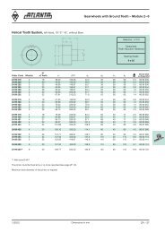
Overview of Integrated <strong>Rack</strong>90° Arrangement 180° Arrangement– Adjusting between rack and rail not necessary– Space-saving and performance-optimized design can be realized– Different types of integrated racks allows best price-performance-ratio– Allows assembling of integrated rack and rail outside the machine– On-site mounting of integrated rack and rail with corresponding device– Continuous linking of the integrated rack with rails– Additional requirement: threads in the rail for the 90° arrangementHelical Integrated <strong>Rack</strong>Class Quality Module Total Tooth Thickness Max. Feed Force per Applications (Examples)Pitch Tolerance Length Pinion Contact/ErrorTooth Wide(µm/m) (µm) (mm) (kN/width)HPIRHighPrecisionIntegrated<strong>Rack</strong>BIRBasicIntegrated<strong>Rack</strong>6 2 36 -37 960 6.8/24 Machine Tools, Wood, Plastic3 36 -37 960 12.0/29 Working Machines4 36 -37 960 23.5/399 2 150 -110 1920 1.8/25 Pick and Place Applicaions3 150 -110 1920 3.0/304 150 -110 1920 5.0/40Straight Integrated <strong>Rack</strong>Class Quality Module Total Tooth Thickness Max. Feed Force per Applications (Examples)Pitch Tolerance Length Pinion Contact/ErrorTooth Wide(µm/m) (µm) (mm) (kN/width)HPIRHighPrecisionIntegrated<strong>Rack</strong>BIRBasicIntegrated<strong>Rack</strong>6 5 36 -37 960 5/24 Machine Tools, Wood, Plastic10 36 -37 960 12/29 Working Machines13.33 36 -37 960 23/399 5 150 -110 1920 1.5/25 Pick and Place Applicaions10 150 -110 1920 5.5/3013.33 150 -110 1920 6.5/401/2012Dimensions in mm ZC – 1
Overview of Integrated <strong>Rack</strong>Straight/Heat-TreatmentSeries Helical Module of TeethPageHPIR49 .. ... Helical 1) 2, 3, 4 Induction-Hardened 6 h 25 ZC-4/549 .. ... Straight 5, 10, 13.33 mm Induction-Hardened 6 h 25 ZC-8/9BIR49 .. ... Helical 1) 2, 3, 4 Soft 9 e 27 ZC-6/749 .. ... Straight 5, 10, 13.33 mm Soft 9 e 27 ZC-10/11Mounting Guide for 90° VersionZC-12Mounting Guide for 180° VersionZC-13Selection and Load Tables ZC-15 – 20Electronically Controlled Lubricators, Sliding-Type Lubricating Brushes ZE-2 – 6and Hose-Connection SetsFelt Gear and Mounting Shaft ZE - 7 – 8Mounting ZF - 91) All our helical racks are right hand, except the companion racks, which are left hand!ZC – 2 Dimensions in mm1/2012
HPIR Integrated <strong>Rack</strong> Module 2 – 4Quality 6 – 90° Versionbfx45°hh 0h kd 1d 2d 3L 1taa 1l l llllhfx45°19°31'42"Order N° N°Code Module L 1 L 2 of Teeth b h k h o f a I of Holes h d 1 d 2 t a 1 d 349 29 197 2 960 6.70 144 19 19.50 17.50 1 10 60 16 7.5 4.5 7.5 5.3 30 4.5 2.749 29 397 2 480 6.70 72 19 19.50 17.50 1 10 60 8 7.5 4.5 7.5 5.3 30 4.5 1.349 29 187 2 960 8.50 144 24 24.50 22.50 1 10 60 16 10.0 6.0 9.5 8.5 30 6.0 4.249 29 387 2 480 8.50 72 24 24.50 22.50 1 10 60 8 10.0 6.0 9.5 8.5 30 6.0 2.149 39 197 3 960 10.30 96 29 29.75 26.75 2 10 60 16 11.5 7.0 11.0 9.0 30 7.0 5.649 39 397 3 480 10.30 48 29 29.75 26.75 2 10 60 8 11.5 7.0 11.0 9.0 30 7.0 2.849 49 197 4 960 13.83 72 39 39.75 35.75 2 20 80 12 14.0 10.0 15.0 9.0 40 10.0 10.549 49 397 4 480 13.83 36 39 39.75 35.75 2 20 80 6 14.0 10.0 15.0 9.0 40 10.0 5.249 49 177 4 960 13.83 72 39 48.75 44.75 2 20 80 12 17.0 10.0 15.0 9.0 40 10.0 13.049 49 377 4 480 13.83 36 39 48.75 44.75 2 20 80 6 17.0 10.0 15.0 9.0 40 10.0 6.549 49 887 4 840 17.38 63 49 58.00 54.00 2 30 105 8 22.5 14.0 20.0 13.0 60 14.0 17.3Total pitch error: GT f /1000 ≤ 0.036 mm• Teeth induction-hardened and ground• Material C45• Ground on all sides after hardeningMounting racks, see page ZF-2.To achieve precision rack joints, we recommend our patented rack assembly kit, see page ZF-4.For lubrication of racks & pinions, we recommend our automatic lubrication systems, see page ZE-1.For the calculation and selection of the rack & pinion drive, see page ZD-1.ZC – 4 Dimensions in mm1/2012
HPIR Integrated <strong>Rack</strong> Module 2 – 4Quality 6 – 180° Versionbfx45°t 3h 0h kd 1d 2m 3h 3L 2aa 1llllL 1llllllthfx45°19°31'42"Order N° N°Code Module L 1 L 2 of Teeth b h k h o f a I of Holes h d 1 d 2 t a 1 m 3 h 3 t 349 29 107 2 960 6.70 144 19 19.50 17.50 1 10 60 16 7.5 5.8 10 6 30 M4 7.5 8.0 2.749 29 117 2 960 8.50 144 24 24.50 22.50 1 10 60 16 10.0 7.0 11 7 30 M5 10.0 11.0 4.249 39 107 3 960 10.30 96 29 29.75 26.75 2 10 60 16 11.5 10.0 15 9 30 M6 11.5 13.5 5.649 49 107 4 960 13.83 72 39 39.75 35.75 2 20 80 12 14.0 12.0 18 12 40 M8 14.0 16.0 10.549 49 127 4 960 13.83 72 39 48.75 44.75 2 20 80 12 17.0 12.0 18 12 40 M8 17.0 16.0 13.049 49 807 4 840 17.38 63 49 58.00 54.00 2 30 105 8 22.5 14.0 20 13 60 M12 22.5 25.0 17.3Total pitch error: GT f /1000 ≤ 0.036 mm• Teeth induction-hardened and ground• Material C45• Ground on all sides after hardeningMounting racks, see page ZF-2.To achieve precision rack joints, we recommend our patented rack assembly kit, see page ZF-4.For lubrication of racks & pinions, we recommend our automatic lubrication systems, see page ZE-1.For the calculation and selection of the rack & pinion drive, see page ZD-1.1/2012Dimensions in mm ZC – 5
BIR Integrated <strong>Rack</strong> Module 2 – 4Quality 9 – 90° Versionfx45°bhh 0h kd 1d 2d 3L 2aa 1llllL 1llllllthfx45°19°31'42"Order N° N°Code Module L 1 L 2 of Teeth b h k h o f a I of Holes h d 1 d 2 t a 1 d 349 29 292 2 1920 7.10 288 20 19.50 17.50 1 10 60 32 7.5 4.5 7.5 5.3 30 4.5 5.449 29 282 2 1920 8.90 288 25 24.50 22.50 1 10 60 32 10.0 6.0 9.5 8.5 30 6.0 8.449 39 292 3 1920 10.60 192 30 29.75 26.75 2 10 60 32 11.5 7.0 11.0 9.0 30 7.0 11.249 49 292 4 1920 14.20 144 40 39.75 35.75 2 20 80 24 14.0 10.0 15.0 9.0 40 10.0 21.549 49 272 4 1920 14.54 144 41 48.75 44.75 2 20 80 24 17.0 10.0 15.0 9.0 40 10.0 29.9Total pitch error GT f /1000 ≤ 0.150 mm.• Milled teeth• Material C45• Bright steelMounting racks see page ZF-2.To achieve precision rack joints, we recommend our patented rack assembly kit, see page ZF-4.For lubrication of racks & pinions, we recommend our automatic lubrication systems, see page ZE-1.For the calculation and selection of the rack & pinion drive, see page ZD-1.ZC – 6 Dimensions in mm1/2012
BIR Integrated <strong>Rack</strong> Module 2 – 4Quality 9 – 180° Versionfx45°bt 3h 0h kd 1d 2hm 3h 3L 2allL 1llltfx45°a 1lllll19°31'42"Order N° N°Code Module L 1 L 2 of Teeth b h k h o f a I of Holes h d 1 d 2 t a 1 m 3 h 3 t 349 29 202 2 1920 7.1 288 20 19.50 17.50 1 10 60 32 7.5 5.8 10 6 30 M4 7.5 8.0 5.449 29 212 2 1920 8.9 288 25 24.50 22.50 1 10 60 32 10.0 7.0 11 7 30 M5 10.0 11.0 8.449 39 202 3 1920 10.6 192 30 29.75 26.75 2 10 60 32 11.5 10.0 15 9 30 M6 11.5 13.5 11.249 49 202 4 1920 14.2 144 40 39.75 35.75 2 20 80 24 14.0 12.0 18 12 40 M8 14.0 16.0 21.5Total pitch error GT f /1000 ≤ 0.150 mm.• Milled teeth• Material C45• Bright steelMounting racks see page ZF-2.To achieve precision rack joints, we recommend our patented rack assembly kit, see page ZF-4.For lubrication of racks & pinions, we recommend our automatic lubrication systems, see page ZE-1.For the calculation and selection of the rack & pinion drive, see page ZD-1.1/2012Dimensions in mm ZC – 7
HPIR Integrated <strong>Rack</strong> Pitch 5, 10, 13.33Quality 6 – 90° VersionL 1balllllfx45°hh 0h kd 1d 2d 3a 1lllllhfx45°tOrder N° N°Code Pitch L 1 of Teeth b h k h o f a I of Holes h d 1 d 2 t a 1 d 349 77 197 5 960 192 19 19.50 17.91 1 10 60 16 7.5 4.5 7.5 5.3 30 4.5 2.749 77 187 5 960 192 24 24.50 22.91 1 10 60 16 10.0 6.0 9.5 8.5 30 6.0 4.249 97 197 10 960 96 29 29.75 26.57 2 10 60 16 11.5 7.0 11.0 9.0 30 7.0 5.649 47 197 13.33 960 72 39 39.75 35.50 2 20 80 12 14.0 10.0 15.0 9.0 40 10.0 10.5Total pitch error: GT f /1000 ≤ 0.036 mm• Teeth induction-hardened and ground• Material C45• Ground on all sides after hardeningMounting racks see page ZF-2 and ZF-4-5.To achieve precision rack joints, we recommend our patented rack assembly kit, see page ZF-4.For lubrication of racks & pinions, we recommend our automatic lubrication systems, see page ZE-1.For the calculation and selection of the rack & pinion drive, see page ZD-1.ZC – 8 Dimensions in mm1/2012
HPIR Integrated <strong>Rack</strong> Pitch 5, 10, 13.33Quality 6 – 180° VersionL 1balllllfx45°t 3h 0h kd 1d 2hm 3h 3a 1llllltfx45°Order N° N°Code Pitch L 1 of Teeth b h k h o f a I of Holes h d 1 d 2 t a 1 m 3 h 3 t 349 77 107 5 960 192 19 19.50 17.91 1 10 60 16 7.5 5.8 10 6 30 M4 7.5 8.0 2.749 77 117 5 960 192 24 24.50 22.91 1 10 60 16 10.0 7.0 11 7 30 M5 10.0 11.0 4.249 97 107 10 960 96 29 29.75 26.57 2 10 60 16 11.5 10.0 15 9 30 M6 11.5 13.5 5.649 47 107 13.33 960 72 39 39.75 35.50 2 20 80 12 14.0 12.0 18 12 40 M8 14.0 16.0 10.5Total Pitch Error: GT f /1000 ≤ 0.036 mm• Teeth induction-hardened and ground• Material C45• Ground on all sides after hardeningMounting racks see page ZF-2 and ZF-4-5.To achieve precision rack joints, we recommend our patented rack assembly kit, see page ZF-4.For lubrication of racks & pinions, we recommend our automatic lubrication systems, see page ZE-1.For the calculation and selection of the rack & pinion drive, see page ZD-1.1/2012Dimensions in mm ZC – 9
BIR Integrated <strong>Rack</strong> Pitch 5, 10, 13.33Quality 9 – 90° VersionalllL 1llfx45°bh 0h kd 1d 2d 3hha 1lllllfx45°tOrder N° N°Code Pitch L 1 of Teeth b h k h o f a I of Holes h d 1 d 2 t a 1 d 349 77 292 5 1920 384 20 19.50 17.91 1 10 60 32 7.5 4.5 7.5 5.3 30 4.5 5.449 77 282 5 1920 384 25 24.50 22.91 1 10 60 32 10.0 6.0 9.5 8.5 30 6.0 8.449 97 292 10 1920 192 30 29.75 26.57 2 10 60 32 11.5 7.0 11.0 9.0 30 7.0 11.249 47 292 13.33 1920 144 40 39.75 35.50 2 20 80 24 14.0 10.0 15.0 9.0 40 10.0 21.5Total pitch error GT f /1000 ≤ 0.150 mm.• Milled teeth• Material C45• Bright steelMounting racks see page ZF-2 and ZF-4-5.To achieve precision rack joints, we recommend our patented rack assembly kit, see page ZF-4.For lubrication of racks & pinions, we recommend our automatic lubrication systems, see page ZE-1.For the calculation and selection of the rack & pinion drive, see page ZD-1.ZC – 10 Dimensions in mm1/2012
BIR Integrated <strong>Rack</strong> Pitch 5, 10, 13.33Quality 9 – 180° VersionalllL 1llfx45°bt 3h 0h kd 1d 2hm 3h 3a 1llllltfx45°Order N° N°Code Pitch L 1 of Teeth b h k h o f a I of Holes h d 1 d 2 t a 1 m 3 h 3 t 349 77 202 5 1920 384 20 19.50 17.91 1 10 60 32 7.5 5.8 10 6 30 M4 7.5 8.0 5.449 77 212 5 1920 384 25 24.50 22.91 1 10 60 32 10.0 7.0 11 7 30 M5 10.0 11.0 8.449 97 202 10 1920 192 30 29.75 26.57 2 10 60 32 11.5 10.0 15 9 30 M6 11.5 13.5 11.249 47 202 13.33 1920 144 40 39.75 35.50 2 20 80 24 14.0 12.0 18 12 40 M8 14.0 16.0 21.5Total Pitch error GT f /1000 ≤ 0.150 mm.• Milled teeth• Material C45• Bright steelMounting racks see page ZF-2 and ZF-4-5.To achieve precision rack joints, we recommend our patented rack assembly kit, see page ZF-4.For lubrication of racks & pinions, we recommend our automatic lubrication systems, see page ZE-1.For the calculation and selection of the rack & pinion drive, see page ZD-1.1/2012Dimensions in mm ZC – 11
Mounting Guide for 90° Version Integrated <strong>Rack</strong>This table with the most usual rails enables (you) to select the rack suitablefor the rail. the permissible feed force of the rack has to be checked,too. the rail has to be selected according to the supplier's specifications.<strong>Rack</strong>s from90° Assembly (Additional threads required in the rail)<strong>ATLANTA</strong> 49 29 197 49 29 187 49 39 197 49 49 197 49 49 177 49 49 88749 29 292 49 29 282 49 39 292 49 49 292 49 49 37749 77 197 49 77 187 49 97 197 49 47 19749 77 292 49 77 282 49 97 292 49 47 292HIWIN LGR 15R LGR 20R LGR 25R LGR 30R LGR 35R LGR 45RAGR 15U AGR 20R AGR 25R AGR 30UHGR 15Z HGR 20Z HGR 25Z HGR 30Z HGR 35Z HGR 45ZIKO LWL 20LWH 15 LWH 20 LWH 25 LWH 30 LWH 35 LWH 45LRX 15 LRX 20 LRX 25 LRX 30 LRX 35 LRX 45INA KUSE 20 KUSE 25 KUSE 30 KUSE 35 KUSE 45KUVE 15 KUVE 20 KUVE 25 KUVE 30 KUVE 35 KUVE 45KUE 15 KUE 20 KUE 25 KUE 30 KUE 35NSK L1H 15 L1H 20 L1H 25 L1H 30 L1H 35 L1H 45L1S 15T L1S 20 L1S 25 L1S 30 L1S 35LY 15 LY 20 LY 25 LY 30 LY 35 LY 45LA 25 LA 30 LA 35 LA 45Schneeberger BM 15 BM 20 BM 25 BM 30 BM 35 BM 45SKF LLBHS 15 LLBHS 20 LLBHS 25 LLBHS 30 LLBHS 35 LLBHS 45LLBUS 20 LLBUS 25 LLBUS 35Star 1605-G15 1605-G20 1605-G25 1605-G30 1605-G35 1605-G451646-G15 1646-G20 1646-G25 1646-G30 1646-G35 1646-G451645-G15 1645-G20 1645-G25 1645-G30 1645-G35 1645-G45THK SSR15 SSR20 SSR25 SSR30 SSR35SHS15 SHS20 SHS25 SHS30 SHS35 SHS45SR15 SR20 SR25 SR30 SR35 SR45HSR15 HSR20 HSR25 HSR30 HSR35 HSR45CSR15 CSR20 CSR25 CSR30 CSR35 CSR45GSR15 GSR20 GSR25 GSR30NSR20TBCMounting DeviceOrder Code 49 01 115 49 01 120 49 01 125 49 01 130 49 01 135 49 01 145The device for mounting racks on rails (patented), is available upon request.ZC – 12 Dimensions in mm1/2012
Mounting Guide for 180° Version Integrated <strong>Rack</strong>This table with the most usual rails enables (you) to select the rack suitablefor the rail. the permissible feed force of the rack has to be checked,too. the rail has to be selected according to the supplier's specifications.<strong>Rack</strong>s from180° Assembly<strong>ATLANTA</strong> 49 29 107 49 29 117 49 39 107 49 49 107 49 49 127 49 49 80749 29 202 49 29 212 49 39 202 49 49 20249 77 107 49 77 117 49 97 107 49 47 10749 77 202 49 77 212 49 97 202 49 47 202HIWIN LGR 15R LGR 20R LGR 25R LGR 30R LGR 35R LGR 45RAGR 15U AGR 20R AGR 25R AGR 30UHGR 15R HGR 20R HGR 25R HGR 30R HGR 35R HGR 45RIKO LWL 20LWH 15 LWH 20 LWH 25 LWH 30 LWH 35 LWH 45LRX 15 LRX 20 LRX 25 LRX 30 LRX 35 LRX 45INA KUSE 20 KUSE 25 KUSE 30 KUSE 35 KUSE 45KUVE 15 KUVE 20 KUVE 25 KUVE 30 KUVE 35 KUVE 45KUE 15 KUE 20 KUE 25 KUE 30 KUE 35NSK L1H 15 L1H 20 L1H 25 L1H 30 L1H 35 L1H 45L1S 15T L1S 20 L1S 25 L1S 35LY 15 LY 20 LY 25 LY 30 LY 35 LY 45LA 25 LA 30 LA 35 LA 45Schneeberger BM 15 BM 20 BM 25 BM 30 BM 35 BM 45SKF LLBHS 15 LLBHS 20 LLBHS 25 LLBHS 30 LLBHS 35 LLBHS 45LLBUS 20 LLBUS 25 LLBUS 35Star 1605-G15 1605-G20 1605-G25 1605-G30 1605-G35 1605-G451646-G15 1646-G20 1646-G25 1646-G30 1646-G35 1646-G451645-G15 1645-G20 1645-G25 1645-G30 1645-G35 1645-G45THK SSR15 SSR20 SSR25 SSR35SHS15 SHS20 SHS25 SHS30 SHS35 SHS45SR20 SR25 SR35 SR45HSR15 HSR20 HSR25 HSR30 HSR35 HSR45CSR15 CSR20 CSR25 CSR30 CSR35 CSR45GSR15 GSR20 GSR25 GSR30RSR20Mounting DeviceOrder Code 49 01 215 49 01 220 49 01 225 49 01 230 49 01 235 49 01 245The device for mounting racks on rails (patented), is available upon request.1/2012Dimensions in mm ZC – 13