Designing a Linear Li-Ion Battery Charger for ... - Arrow Electronics
Designing a Linear Li-Ion Battery Charger for ... - Arrow Electronics
Designing a Linear Li-Ion Battery Charger for ... - Arrow Electronics
- No tags were found...

You also want an ePaper? Increase the reach of your titles
YUMPU automatically turns print PDFs into web optimized ePapers that Google loves.
4.2VCV 84%(Equation 2)5.0V3.0VBAT 3.0V 60%(Equation 3)5.0VDuring a typical Constant-Current (CC) charging mode, the efficiency moves from 60% to84%. The efficiency will stay at 84% <strong>for</strong> the Constant-Voltage (CV) charging mode. Thus,a LDO topology works well in single cell <strong>Li</strong>-<strong>Ion</strong> battery charger designs when the inputvoltage is about 5V. A LDO topology also reduces cost by omitting inductors, and itavoids EMI challenges associated with switching topologies. However, if a fast-chargingcurrent above 1A is required, a switching topology should be considered. Equation 4presents a power-dissipation calculation that illustrates this:P DISSIPATION = I CHARGE x (V IN – V OUT ) = 2A (5V – 3V) = 4 Watts (Equation 4)In this example, a battery charging current of 2 Amperes and a battery voltage of 3V isselected, to show the worst condition in CC mode. An input voltage of 5V is selected tosimplify the calculation. When designing a system, the worst condition that is based upona given tolerance should be considered.Even <strong>for</strong> a 35°C/Watt thermal-rated 4 mm x 4 mm QFN package, it is difficult to dissipate4 Watts, as shown in Equation 5.35°C/Watt x 4 Watts = 144°C (Equation 5)A room temperature of 25 °C with an additional 144°C introduces a temperature of 169°Cin a system. A junction temperature of 169°C is over the thermal shutdown threshold of atypical die temperature. Well-designed <strong>Li</strong>-<strong>Ion</strong> charging-management ICs should includethermal feedback that reduces the charge current when temperature begins to rise tothreshold levels.Baseline <strong><strong>Li</strong>near</strong> <strong>Li</strong>-<strong>Ion</strong> <strong>Battery</strong> <strong>Charger</strong>sBaseline linear <strong>Li</strong>-<strong>Ion</strong> battery chargers are usually low cost and have a low pin count andlow passive-component requirements. They are often available in packages such asSOT-23, MSOP and DFN. With the maturation of semiconductor technology, mostbaseline linear battery chargers are fully integrated. The typical pin count is between fiveto ten pins.
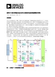
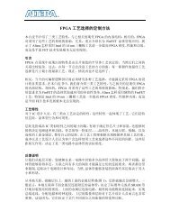
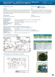
Figure 1:A Typical Base <strong>Li</strong>ne <strong>Li</strong>-<strong>Ion</strong> <strong>Battery</strong> <strong>Charger</strong>Charging a <strong>Li</strong>-<strong>Ion</strong> battery safely is usually the primary and only goal <strong>for</strong> baseline chargers.No fancy features are required. Figure 1 depicts a simple 5-pin battery charger thatrequires a minimum of three components in order to operate—an input capacitor, anoutput capacitor and a programming resistor. Additional pins may be available <strong>for</strong>functions such as extra status indicators, power-good indicators, battery temperaturemonitoring, timer and logic current control.USB-based <strong><strong>Li</strong>near</strong> <strong>Li</strong>-<strong>Ion</strong> <strong>Battery</strong> <strong>Charger</strong>sIn addition to linking peripherals and computers, the USB protocol also delivers highspeed at an economic cost. Connecting devices and peripherals through USB ports to acomputer has become the most popular method. With a voltage range of 4.75 to 5.25V,USB is an excellent candidate <strong>for</strong> restoring energy back to single-cell <strong>Li</strong>-<strong>Ion</strong> battery cellsor packs as previously discussed. There are many methods <strong>for</strong> charging single cell <strong>Li</strong>-<strong>Ion</strong>batteries.Table 3 lists a few basic methods <strong>for</strong> designing a single-cell <strong>Li</strong>-<strong>Ion</strong> battery charger fromUSB ports.Figure 2:Dual-Input <strong>Li</strong>-<strong>Ion</strong> <strong>Battery</strong> <strong>Charger</strong>
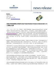
The first method utilizes a low-power USB port <strong>for</strong> a fixed charging current. This methodusually ends up below the absolute maximum current of a low-speed USB port, which is100 mA. Due to the resistor’s tolerance, charge current, and supply current, this chargecurrent is typically under 90 mA. This simply treats an USB port as a 5V, 100 mA-ratedpower supply. To take advantage of high-speed USB port, an external MOSFET can beused to set two different charging currents when driving the gate low or high. A highspeedUSB port allows an absolute maximum current of 500 mA, but a port shouldalways start at low speed until verification is complete.An integrated MOSFET <strong>for</strong> setting two different charging currents simplifies this designand offers either a preset or resistor-programmable charge current. Figure 2 shows anexample that offers three different charge current settings and can seamlessly switchbetween a Wall Wart (AC-to-DC adapter) and a USB port. When a Wall Wart is present,the maximum charging current can easily be higher than 500 mA from a high-speed USBport. When solely a USB cable is applied, the charge current will be based upon the logiclevel high or low. Some designs require only one input-power rail, but a different inputtype can be set by communication between interfaces. Typically, the preset USBcharging current is below 450 mA <strong>for</strong> a high-speed USB port <strong>for</strong> the same reason as in alow-speed USB port. Proper design methods should also limit the amount of inputcurrent drawn from the USB port <strong>for</strong> safety, and in order to meet USB specifications.MethodDescription1 Fixed Charge Current (Typically < 90 mA)2 External MOSFET Charge-Current Control3 Integrated MOSFET <strong>for</strong> Multiple Charge-Current Controls4 Logic Dual-Input Charge Control (Typically 450 mA/90 mA)5 Input Current <strong>Li</strong>mit Control, with Maximum Charge-CurrentSettingTable 3:Methods <strong>for</strong> Charging from USB PortsSystem Load-Sharing and Power-Path Management-Type <strong>Li</strong>-<strong>Ion</strong> <strong>Battery</strong> <strong>Charger</strong>As the number of features in today’s portable devices increases, requirements <strong>for</strong> properbattery management also increase. In space-constrained applications, highly-integratedpower-rail controls advance a designer’s experience. Each power rail needs to be wellmanage, <strong>for</strong> seamless switching among input power path, system load and battery cell.
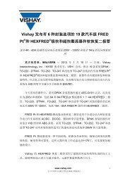
Figure 3:System Load-Sharing <strong>Li</strong>-<strong>Ion</strong> <strong>Battery</strong> <strong>Charger</strong>Figure 3 demonstrates a typical application circuit of a <strong>Li</strong>-<strong>Ion</strong> battery charger with systemload-sharing and power-path management features that can switch between powersources. One advantage to using this design instead of a traditional method is that eachpower rail is managed and the battery is in support mode when the input voltage isinsufficient to keep the output voltage steady. Sometimes, additional features such aslow-power indicators or controls, and power-source selection offer functionality beyondjust restoring energy back to batteries.Additional <strong>Battery</strong>-<strong>Charger</strong> FeaturesAs <strong>Li</strong>-<strong>Ion</strong> batteries are increasingly used, safety and functionality requirements alsoincrease. These requirements may come from internal organizations that promotehazard-free design guidance; local governmental regulations or policies; regionalproduct-manufacturer preference; battery-manufacturer specifications; a designer’s levelof experience, or an end-user’s habits. Common functions include timers <strong>for</strong> eachcharging stage; input over-voltage protection; communication protocols, multiplechannels of regulated outputs; and battery authentication, among others.
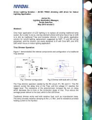
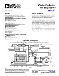
Figure 4:Charge Current Terminates When Input Over-voltage Protection is ActivatedFigure 4 shows an input over-voltage protection feature of a single cell <strong>Li</strong>-<strong>Ion</strong> batterycharger. The output-charge current terminates when the input voltage passes theprotection threshold, and resumes once the input voltage falls back to the designedrange as shown in Figure 5. This has been recommended <strong>for</strong> mobile-devices sinceDecember 2006 as a technical requirement and test method of charger interfaces <strong>for</strong>mobile telecommunication terminal equipment.
Figure 5:Charge Current Resumes<strong>Li</strong>miting the input voltage <strong>for</strong> a linear battery charger keeps end-users from incorrectlyusing Wall Wart or AC-to-DC adapters, and prevents voltage spikes. Recall Equation 4:P DISSIPATION = I CHARGE x (V IN – V OUT )P DISSIPATION = 1A x (7V – 3V) = 4WattsAssuming the charge current is 1A, if the input and output voltages (battery voltage)increase, power dissipation also increases. There<strong>for</strong>e, when the differences betweeninput and battery voltages increase to 4V, the power dissipation is 4W.SummaryGreen technology is always a hot topic. Engineers and scientists constantly work toimprove existing designs and offer better solutions <strong>for</strong> society. <strong>Li</strong>-<strong>Ion</strong> batteries can bedesigned with fuel cells, photovoltaic solar cells, hydro power and wind power as storage,back-up or supportive power. Highly-integrated linear solutions may overcome hurdles inlow-power designs, such as compactness and simplicity. When intelligence, efficiency orpower dissipation are concerns, designers should survey their solutions thoroughly andunderstand the trade-offs between plat<strong>for</strong>ms that are available. When designing withbatteries or any power systems, safety is always the first priority.For more in<strong>for</strong>mation regarding the in<strong>for</strong>mation presented in this article, visit, visithttp://www.microchip.com/battery. Please also visit http://www.analogtalk.com to viewMicrochip’s analog technology blog.
References:[1] Universal Serial BUS 2.0/3.0 Specification[2] Technical Requirements and Test Method of <strong>Charger</strong> and Interface <strong>for</strong> MobileTelecommunication Terminal Equipment###Note: The Microchip name and logo are registered trademarks of Microchip Technology Inc. in the U.S.A.and other countries. All other trademarks mentioned herein are property of their respective companies.