OBD System Operation Summary for Hybrid Electric Vehicles(HEV)
OBD System Operation Summary for Hybrid Electric Vehicles(HEV)
OBD System Operation Summary for Hybrid Electric Vehicles(HEV)

Create successful ePaper yourself
Turn your PDF publications into a flip-book with our unique Google optimized e-Paper software.
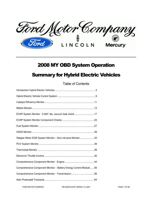
2008 MY <strong>OBD</strong> <strong>System</strong> <strong>Operation</strong><strong>Summary</strong> <strong>for</strong> <strong>Hybrid</strong> <strong>Electric</strong> <strong>Vehicles</strong>Table of ContentsIntroduction <strong>Hybrid</strong> <strong>Electric</strong> <strong>Vehicles</strong>................................................................. 3<strong>Hybrid</strong> <strong>Electric</strong> Vehicle Control <strong>System</strong> ............................................................ 9Catalyst Efficiency Monitor...............................................................................11Misfire Monitor...................................................................................................13EVAP <strong>System</strong> Monitor - 0.020” dia. vacuum leak check...............................17EVAP <strong>System</strong> Monitor Component Checks...................................................23Fuel <strong>System</strong> Monitor ........................................................................................27HO2S Monitor ...................................................................................................29Stepper Motor EGR <strong>System</strong> Monitor – Non-intrusive Monitor ......................33PCV <strong>System</strong> Monitor........................................................................................39Thermostat Monitor ..........................................................................................39Electronic Throttle Control................................................................................40Comprehensive Component Monitor - Engine...............................................44Comprehensive Component Monitor – Battery Energy Control Module......55Comprehensive Component Monitor - Transmission....................................56Aisin Powersplit Transaxle...............................................................................64FORD MOTOR COMPANY REVISION DATE: MARCH 13, 2007 PAGE 1 OF 69
PCM On Board Diagnostic Executive .............................................................66Exponentially Weighted Moving Average.......................................................67I/M Readiness Code.........................................................................................69Catalyst Temperature Model ...........................................................................70Serial Data Link MIL Illumination.....................................................................70FORD MOTOR COMPANY REVISION DATE: MARCH 13, 2007 PAGE 2 OF 69
Introduction <strong>Hybrid</strong> <strong>Electric</strong> <strong>Vehicles</strong><strong>HEV</strong> Powertrain DescriptionA hybrid electric vehicle is powered by a conventional engine with an electric motor added <strong>for</strong> enhanced fueleconomy and reduced emissions. The electric motor can also be used to boost power and enhance per<strong>for</strong>mance(like an extra "charge"). Daily recharging plug-ins aren't needed. This type of vehicle is well suited <strong>for</strong> theenvironmentally aware driver who wants better fuel economy and fewer pollutants, but doesn't want the hassle ofplug-ins.A vehicle can be "more" of a hybrid than another. There are two levels of "hybridization," mild and full.Full hybrids have all of the functions and capabilities of a mild hybrid, plus more advanced features. With both, theengine turns off when it is not needed, reducing fuel waste, and instantly restarts when the need <strong>for</strong> power isdetected. In addition, both hybrids provide electric assist, in that the gasoline engine gets a boost of electric powerfrom the battery pack. This provides additional acceleration per<strong>for</strong>mance when needed, without additional use offuel. However, a full hybrid usually has a substantially higher powered battery than a mild hybrid.A full hybrid also gives you regenerative braking (meaning vehicle energy that would otherwise would be wasted, iscollected during braking to recharge the battery) while a mild hybrid has only mild regenerative braking. And only afull hybrid provides an electric launch. In full hybrid systems only, the electric motor can power the vehicle, evenwhile the engine is off. The electric motor can be used to drive in pure electric mode even when accelerating froma complete stop. An easy way to tell the difference between a mild and a full hybrid is that a full hybrid gets bettermpg in the city than on the highway.FORD MOTOR COMPANY REVISION DATE: MARCH 13, 2007 PAGE 3 OF 69
Benefits of <strong>Hybrid</strong> <strong>Electric</strong> <strong>Vehicles</strong>• Reduces emissions by increasing average engine efficiency.• Engine shuts down, when the vehicle is stopped.• <strong>Electric</strong> motor boosts acceleration per<strong>for</strong>mance.• Regenerative brakes recapture energy, to recharge the battery.• Improved fuel economy stretches a tank of gas further, saves you money, and helps you conserve ourlimited petroleum resources.• Driving per<strong>for</strong>mance is optimized because both the gas engine and electric motor are working <strong>for</strong> you.• No battery plug-ins required.• An <strong>HEV</strong> offers all the conveniences of conventional vehicles: spacious seating, storage room, creaturecom<strong>for</strong>ts, and extended driving range.• The Ford Escape <strong>HEV</strong> will be delivered, sold, and serviced at local Ford Dealers.FORD MOTOR COMPANY REVISION DATE: MARCH 13, 2007 PAGE 4 OF 69
Key Powertrain ComponentsEngine• 2.3L I-4 Gasoline Engine• Electronic Throttle Control• Atkinson Cycle to improve efficiency byreducing pumping losses• For Otto Cycle, expansion ratio equalscompression ratio• Atkinson Cycle expansion ratio greater thancompression ratio• Leaves intake valve open longer duringcompression stroke pushing air back into intakemanifold• Operates with less vacuum and greater throttleopening to maintain air chargeTransaxle• 36 kW Permanent Magnet AC Generator Motor• 65 kW Permanent Magnet AC Traction Motor• Power Electronics / Voltage Inverter• Planetary gear set and final drive gears• Connected to front 2-wheel or all-wheel drivelineFORD MOTOR COMPANY REVISION DATE: MARCH 13, 2007 PAGE 5 OF 69
Battery• Ni Metal Hydride• 39 kW power rating (new)• Nominal 330V DC operation• 5.5 Amp-hrs capacityNickel-metal hydride batteries (NiMH) have a much longer life cycle than lead acid batteries. In addition to electricvehicles and <strong>HEV</strong>s, they are often used in consumer electronics, computers and medical equipment.FORD MOTOR COMPANY REVISION DATE: MARCH 13, 2007 PAGE 6 OF 69
Propulsion ModesSeries Mode• Used only when vehicle is not moving and theengine is running• Engine may be running <strong>for</strong> battery charging,cabin or battery temperature control, or catalystwarm-up.Positive Split Mode• Engine is ON and driving the generator motorto produce electricity• Power from the engine is split between thedirect path to the road and the path through thegenerator motor• Generator power can flow to the battery or tothe traction motor• The traction motor can operate as a motor or agenerator to make up the difference betweenthe engine power and the desired power• This is the preferred mode whenever thebattery needs to be charged or when atmoderate loads and low vehicle speedsNegative Split Mode• The engine is on and the generator motorconsumes electrical energy to reduce enginespeed• The traction motor can operate as a motor or agenerator to make up the difference betweenthe engine power and the desired power• Typical highway mode• Occurs when the engine needs to be on, thesystem can not be operated in parallel modeand the battery is charged near its upper limitFORD MOTOR COMPANY REVISION DATE: MARCH 13, 2007 PAGE 7 OF 69
<strong>Electric</strong> Mode• The vehicle is propelled by stored electricalenergy only• The engine is turned off• The tractive torque supplied from the tractionmotor• Preferred mode whenever the desired power islow enough such that it can be produced moreefficiently by electrical system than engine• Preferred mode in reverse because the enginecan not deliver reverse torque• Separate electric pump maintains powerassisted steeringCity & Highway Traffic ScenariosStopped• The engine will be off unless it needs to be on <strong>for</strong> reasons other than tractive power (Max A/C, vacuum,catalyst temp, heat, purge, low SOC)Launching• At low speed or low power demand, the launch mode will be electric, unless the engine needs to be on <strong>for</strong>other reasons.• At moderate speed or high desired power, the engine will come on.Entering highway or Passing• At high acceleration demand, the engine power will be boosted with battery power through the tractionmotor to provide quick V-6 like response.Cruising• At light load, the system may operate in parallel, positive split or negative split mode depending on thebattery charge.• At heavy load (due to high speeds, weight, towing or grade), the system will be limited to engine onlyper<strong>for</strong>mance (no battery support).• Limited regenerative braking will be used.Exiting highway• Provides an opportunity <strong>for</strong> regenerative braking.Braking• At high speed, the engine torque is ramped down, the traction motor regenerates to a limit and thefoundation brakes are applied as necessary (at the traction motor or battery regen limits).• At moderate and low speed, the engine will be turned off.FORD MOTOR COMPANY REVISION DATE: MARCH 13, 2007 PAGE 8 OF 69
<strong>Hybrid</strong> <strong>Electric</strong> Vehicle Control <strong>System</strong>Escape <strong>HEV</strong> Powertrain Control <strong>System</strong>PCM – Powertrain Control ModuleTCM – Transmission Control ModuleBECM – Battery Energy Control ModuleBSCM – Brake <strong>System</strong> Control ModuleAPPS – Acceleration Pedal Position SensorBPPS – Brake Pedal Position Sensor (master cylinder pressure)PRNDL – Transmission Range SensorSC – Speed ControlPRNDLAPPSSCBPPSdeterminedesiredwheel torqueBSCM /RegenerativeBrakesdeterminegear modedeterminetorque signtorque modificationrequestgear mode+++PCMtorquelimit &dashpotdrivertorquedesiredengine torque desiredenergymanagement& controlEngineonewayclutchtotal torque desired,engine speed desired,generator brakecommand, generatormodeTCM/Trans-Axleplanetaryringsunringbrakegeneratorhigh voltage busmotorBECM/BatteryThe <strong>Hybrid</strong> <strong>Electric</strong> Vehicle Control <strong>System</strong> uses four modules to control hybrid electric powertrain functions:The Powertrain Control Module control overall vehicle system functions as well as engine operation.The Transmission Control Module controls the transaxle as well as generator and motor functions.The Battery Energy Control Module controls the high voltage battery pack.The Brake <strong>System</strong> Control Module controls the regenerative braking functions.All these modules use CAN communication <strong>for</strong> all diagnostic functions and normal-mode communications.The Powertrain Control Module (PCM) is a stand-alone <strong>OBD</strong>-II control module and meets all J1979 requirements.These include generic PIDs, freeze frame storage, pending and confirmed DTC retrieval and clearing, Mode 06test data, Mode 08 evap system test and Mode 09 VIN, CALID and CVN. The <strong>OBD</strong>-II monitors <strong>for</strong> the engine aresimilar to the monitors used by a conventional gasoline vehicle. The basic difference between a conventionalgasoline engine and the hybrid engine is that the engine often shuts down while in electric mode. This sometimesrequires active intervention by the diagnostic executive to ensure that all <strong>OBD</strong>-II monitor can complete.The Transmission Control Module (TCM) is a stand-alone <strong>OBD</strong>-II control module and meets all J1979requirements. These include generic PIDs, freeze frame storage, pending and confirmed DTC retrieval andclearing, and Mode 09 CALID and CVN. Some of the <strong>OBD</strong>-II monitors <strong>for</strong> transmission are similar to the monitorsused by a conventional transmission; however, many of the monitors are unique to the hybrid generator andmotor sensors and controls. The TCM is housed within the transmission case and is not serviceable with theexception of reflashing memory.FORD MOTOR COMPANY REVISION DATE: MARCH 13, 2007 PAGE 9 OF 69
The Battery Energy Control Module (BECM) is not a stand-alone <strong>OBD</strong>-II control module. The battery modulesends fault in<strong>for</strong>mation to the PCM. The PCM stores and reports freeze frame and DTCs <strong>for</strong> the BECM. TheBECM is housed within the battery pack and is not serviceable with the exception of reflashing memory. As aresult, the BECM supports J1979 Mode 09 CALID and CVN.The Brake <strong>System</strong> Control Module (BSCM) is not an <strong>OBD</strong>-II control module because there are no regenerativebraking faults that affect emissions.FORD MOTOR COMPANY REVISION DATE: MARCH 13, 2007 PAGE 10 OF 69
Catalyst Efficiency MonitorThe Catalyst Efficiency Monitor uses an oxygen sensor be<strong>for</strong>e and after the catalyst to infer the hydrocarbonefficiency based on oxygen storage capacity of the ceria and precious metals in the washcoat. Under normal,closed-loop fuel conditions, high efficiency catalysts have significant oxygen storage. This makes the switchingfrequency of the rear HO2S very slow and reduces the amplitude of those switches as compared to the switchingfrequency and amplitude of the front HO2S. As catalyst efficiency deteriorates due to thermal and/or chemicaldeterioration, its ability to store oxygen declines. The post-catalyst HO2S signal begins to switch more rapidly withincreasing amplitude, approaching the switching frequency and amplitude of the pre-catalyst HO2S. Thepredominant failure mode <strong>for</strong> high mileage catalysts is chemical deterioration (phosphorus deposition on the frontbrick of the catalyst), not thermal deterioration.Index Ratio MethodIn order to assess catalyst oxygen storage, the catalyst monitor counts front HO2S switches during part-throttle,closed-loop fuel conditions after the engine is warmed-up and inferred catalyst temperature is within limits. Frontswitches are accumulated in up to three different air mass regions or cells. While catalyst monitoring entryconditions are being met, the front and rear HO2S signal lengths are continually being calculated. When therequired number of front switches has accumulated in each cell (air mass region), the total signal length of the rearHO2S is divided by the total signal length of front HO2S to compute a catalyst index ratio. An index ratio near 0.0indicates high oxygen storage capacity, hence high HC efficiency. An index ratio near 1.0 indicates low oxygenstorage capacity, hence low HC efficiency. If the actual index ratio exceeds the threshold index ratio, the catalyst isconsidered failed.General Catalyst Monitor <strong>Operation</strong>If the catalyst monitor does not complete during a particular driving cycle, the already-accumulated switch/signallengthdata is retained in Keep Alive Memory and is used during the next driving cycle to allow the catalyst monitora better opportunity to complete, even under short or transient driving conditions.Rear HO2S sensors can be located in various ways to monitor different kinds of exhaust systems. In-line enginesand many V-engines are monitored by individual bank. A rear HO2S sensor is used along with the front, fuelcontrolHO2S sensor <strong>for</strong> each bank. Two sensors are used on an in-line engine; four sensors are used on a V-engine.Most vehicles that are part of the “LEV” catalyst monitor phase-in will monitor less than 100% of the catalystvolume – often the first catalyst brick of the catalyst system. Partial volume monitoring is done on LEV and ULEVvehicles in order to meet the 1.75 * emission-standard. The rationale <strong>for</strong> this practice is that the catalysts nearestthe engine deteriorate first, allowing the catalyst monitor to be more sensitive and illuminate the MIL properly atlower emission standards.Many applications that utilize partial-volume monitoring place the rear HO2S sensor after the first light-off catalystcan or, after the second catalyst can in a three-can per bank system. (A few applications placed the HO2S in themiddle of the catalyst can, between the first and second bricks.)All vehicles employ an Exponentially Weighted Moving Average (EWMA) algorithm to improve the robustness ofthe FTP catalyst monitor. During normal customer driving, a malfunction will illuminate the MIL, on average, in 3 to6 driving cycles. If KAM is reset (battery disconnected), a malfunction will illuminate the MIL in 2 driving cycles. Seethe section on EWMA <strong>for</strong> additional in<strong>for</strong>mation.FORD MOTOR COMPANY REVISION DATE: MARCH 13, 2007 PAGE 11 OF 69
CATALYST MONITOR OPERATION:DTCs P0420 Bank 1Monitor executionMonitor SequenceSensors OKMonitoring Durationonce per driving cycleHO2S response test complete and no DTCs (P0133/P0153) prior tocalculating switch ratio, no SAIR pump stuck on DTCs (P0412/P1414), noevap leak check DTCs (P0442/P0456), no EGR stuck open DTCs (P0402)ECT, IAT, TP, VSS, CKPApproximately 900 seconds during appropriate FTP conditionsTYPICAL INDEX RATIO CATALYST MONITOR ENTRY CONDITIONS:Entry condition Minimum MaximumTime since engine start-up (70 o F start)5 secondsEngine Coolant Temp 150 o F 230 o FIntake Air Temp 20 o F 180 o FTime since entering closed loop fuelInferred Rear HO2S sensor Temperature30 sec1000 o FEGR flow (Note: an EGR fault disables EGR) 0% 8%Throttle Position Part Throttle Part ThrottleRate of Change of Throttle Position 0.244 volts /0.050 secVehicle Speed 20 mph 80 mphFuel Level 15%First Air Mass Cell 0.8 lb/min 2.3 lb/minEngine RPM <strong>for</strong> first air mass cell 1,300 rpm 1,800 rpmEngine Load <strong>for</strong> first air mass cell 28% 44%Monitored catalyst mid-bed temp. (inferred) <strong>for</strong> first air mass cell 800 o F 1,600 o FNumber of front O2 switches required <strong>for</strong> first air mass cell 70TYPICAL MALFUNCTION THRESHOLDS:Rear-to-front O2 sensor switch/index-ratio > 0.80 (bank monitor)J1979 CATALYST MONITOR MODE $06 DATAMonitor ID Test ID Description <strong>for</strong> CAN$21 $80 Bank 1 index-ratio and max. limit unitless** NOTE: In this document, a monitor or sensor is considered OK if there are no DTCs stored <strong>for</strong> that componentor system at the time the monitor is running.FORD MOTOR COMPANY REVISION DATE: MARCH 13, 2007 PAGE 12 OF 69
Misfire MonitorThe <strong>HEV</strong> uses the Low Data Rate misfire monitor. The LDR system is capable of meeting “full-range” misfiremonitoring requirements on 4-cylinder engines. The software allows <strong>for</strong> detection of any misfires that occur 6engine revolutions after initially cranking the engine. This meets the new <strong>OBD</strong>-II requirement to identify misfireswithin 2 engine revolutions after exceeding the warm drive, idle rpm.Low Data Rate <strong>System</strong>The LDR Misfire Monitor uses a low-data-rate crankshaft position signal, (i.e. one position reference signal at 10deg BTDC <strong>for</strong> each cylinder event). The PCM calculates crankshaft rotational velocity <strong>for</strong> each cylinder from thiscrankshaft position signal. The acceleration <strong>for</strong> each cylinder can then be calculated using successive velocityvalues. The changes in overall engine rpm are removed by subtracting the median engine acceleration over acomplete engine cycle. The resulting deviant cylinder acceleration values are used in evaluating misfire in the“General Misfire Algorithm Processing” section below.“Profile correction” software is used to “learn” and correct <strong>for</strong> mechanical inaccuracies in crankshaft tooth spacingunder de-fueled engine conditions (requires extended engine shutdown either at key off, or on multiple engineshutdown events during normal vehicle operation, after Keep Alive Memory has been reset). These learnedcorrections improve the high-rpm capability of the monitor <strong>for</strong> most engines. The misfire monitor is not active until aprofile has been learned.Generic Misfire Algorithm ProcessingThe acceleration that a piston undergoes during a normal firing event is directly related to the amount of torque thatcylinder produces. The calculated piston/cylinder acceleration value(s) are compared to a misfire threshold that iscontinuously adjusted based on inferred engine torque. Deviant accelerations exceeding the threshold areconditionally labeled as misfires.The calculated deviant acceleration value(s) are also evaluated <strong>for</strong> noise. Normally, misfire results in a nonsymmetricalloss of cylinder acceleration. Mechanical noise, such as rough roads or high rpm/light load conditions,will produce symmetrical acceleration variations. Cylinder events that indicate excessive deviant accelerations ofthis type are considered noise. Noise-free deviant acceleration exceeding a given threshold is labeled a misfire.The number of misfires are counted over a continuous 200 revolution and 1000 revolution period. (The revolutioncounters are not reset if the misfire monitor is temporarily disabled such as <strong>for</strong> negative torque mode, etc.) At theend of the evaluation period, the total misfire rate and the misfire rate <strong>for</strong> each individual cylinder is computed. Themisfire rate evaluated every 200 revolution period (Type A) and compared to a threshold value obtained from anengine speed/load table. This misfire threshold is designed to prevent damage to the catalyst due to sustainedexcessive temperature (1600°F <strong>for</strong> Pt/Pd/Rh conventional washcoat, 1650°F <strong>for</strong> Pt/Pd/Rh advanced washcoat and1800°F <strong>for</strong> Pd-only high tech washcoat). If the misfire threshold is exceeded and the catalyst temperature modelcalculates a catalyst mid-bed temperature that exceeds the catalyst damage threshold, the MIL blinks at a 1 Hzrate while the misfire is present. If the misfire occurs again on a subsequent driving cycle, the MIL is illuminated. Ifa single cylinder is indicated to be consistently misfiring in excess of the catalyst damage criteria, the fuel injector tothat cylinder may be shut off <strong>for</strong> a period of time to prevent catalyst damage. Up to two cylinders may be disabledat the same time. This fuel shut-off feature is used on all engines starting in the 2005 MY. Next, the misfire rate isevaluated every 1000 rev period and compared to a single (Type B) threshold value to indicate an emissionthresholdmalfunction, which can be either a single 1000 rev exceedence from startup or four subsequent 1000 revexceedences on a drive cycle after start-up. Some vehicles will set a P0316 DTC if the Type B malfunctionthreshold is exceeded during the first 1,000 revs after engine startup. This DTC is normally stored in addition to thenormal P03xx DTC that indicates the misfiring cylinder(s). If misfire is detected but cannot be attributed to a specificcylinder, a P0300 is stored. This may occur on some vehicles at higher engine speeds, <strong>for</strong> example, above 3,500rpm.FORD MOTOR COMPANY REVISION DATE: MARCH 13, 2007 PAGE 13 OF 69
Profile Correction"Profile correction" software is used to "learn" and correct <strong>for</strong> mechanical inaccuracies in the crankshaft positionwheel tooth spacing. Since the sum of all the angles between crankshaft teeth must equal 360 o , a correction factorcan be calculated <strong>for</strong> each misfire sample interval that makes all the angles between individual teeth equal. Toprevent any fueling or combustion differences from affecting the correction factors, learning is done duringextended engine shutdown.In order to minimize learning time <strong>for</strong> profile correction factors, the correction factors are learned after an engineshutdown has been commanded and fuel has been discontinued while the generator spins the engine. In order toprotect the battery, and assure vehicle starting, the following conditions must be met to extend the shutdown:battery temperature and charge state must be within limits (i.e. the battery must be able to spin the engine). Thiscondition occurs either when the key is turned off, or when normal operating conditions dictate an engine shutdown(typically one key off induced shutdown, but may be multiple shutdown events during normal operation). Duringthis extended shutdown, the engine is spun at approximately 1100 rpm, while delta time intervals are captured <strong>for</strong>computation of the correction factors. Average profile correction factors are calculated <strong>for</strong> each of the 4 combustionintervals over approximately 15 engine cycles. This procedure occurs once per KAM reset during the life of thevehicle. In order to assure the accuracy of these corrections, a tolerance is placed on the incoming values suchthat an individual correction factor must be repeatable within the tolerance during learning; this is to reduce thepossibility of learning corrections on rough road conditions which could limit misfire detection capability.Since inaccuracies in the wheel tooth spacing can produce a false indication of misfire, the misfire monitor is notactive until the corrections are learned. In the event of battery disconnection or loss of Keep Alive Memory thecorrection factors are lost and must be relearned. The software may be unable to learn a profile if theinstantaneous profile calculations vary by more than a specified tolerance from the mean values. In this case aP0315 DTC is set.Misfire Monitor <strong>Operation</strong>:DTCsMonitor executionMonitor SequenceSensors OKMonitoring DurationP0300 to P0304 (general and specific cylinder misfire)P0315 (unable to learn profile)P0316 (misfire during first 1,000 revs after start-up)Continuous, misfire rate calculated every 200 or 1000 revsNoneCKP, CMP, no EGR stuck open DTCs (P0402)Entire driving cycle (see disablement conditions below)Typical misfire monitor entry conditions:Entry condition Minimum MaximumTime since engine start-up 0 seconds 0 secondsEngine Coolant Temperature 20 o F 250 o FRPM Range (Full-Range Misfire certified, with 2 revdelay)Profile correction factors learned in KAM2 revs after exceeding 150rpm below “drive” idle rpmYesFuel tank level 15%redline on tach or fuelcutoffFORD MOTOR COMPANY REVISION DATE: MARCH 13, 2007 PAGE 14 OF 69
Typical misfire temporary disablement conditions:Temporary disablement conditions:Closed throttle decel (negative torque, engine being driven)Fuel shut-off due to vehicle-speed limiting or engine-rpm limiting modeHigh rate of change of torque (heavy throttle tip-in or tip out)Typical misfire monitor malfunction thresholds:Type A (catalyst damaging misfire rate): misfire rate is an rpm/load table ranging from 20% at idle to 5% athigh rpm and loadsType B (emission threshold rate): 1.7%J1979 Misfire Mode $06 DataMonitor ID Test ID Description <strong>for</strong> CANA1 $80 Total engine misfire and catalyst damage misfire rate (updated every200 revolutions)A1 $81 Total engine misfire and emission threshold misfire rate (updatedevery 1,000 revolutions)A1 $82 Highest catalyst-damage misfire and catalyst damage threshold misfirerate (updated when DTC set or clears)A1 $83 Highest emission-threshold misfire and emission threshold misfire rate(updated when DTC set or clears)A1 $84 Inferred catalyst mid-bed temperaturepercentpercentpercentpercento CA2 – AD $0B EWMA misfire counts <strong>for</strong> last 10 driving cycles eventsA2 – AD $0C Misfire counts <strong>for</strong> last/current driving cycle eventsA2 – AD $80 Cylinder X misfire rate and catalyst damage misfire rate (updatedevery 200 revolutions)A2 – AD $81 Cylinder X misfire rate and emission threshold misfire rate (updatedevery 1,000 revolutions)percentpercentFORD MOTOR COMPANY REVISION DATE: MARCH 13, 2007 PAGE 15 OF 69
Profile Correction <strong>Operation</strong>DTCsMonitor ExecutionMonitor Sequence:Sensors OK:Monitoring Duration;P0315 - unable to learn profileonce per KAM reset.Profile must be learned be<strong>for</strong>e misfire monitor is active.CKP, CMP, no AICE communication errors, CKP/CMP in synch10 cumulative seconds in conditionsTypical profile learning entry conditions:Entry condition Minimum MaximumEngine in decel-fuel cutout mode <strong>for</strong> 4 engine cyclesBrakes applied N/A N/AEngine RPM 800 rpm 1750 rpmChange in RPM600 rpm/background loopVehicle Speed 0 mph 30 mphLearning tolerance 1.5%Battery temperature-15 degrees CBattery Voltage216 VBattery power discharge limit12 KwFORD MOTOR COMPANY REVISION DATE: MARCH 13, 2007 PAGE 16 OF 69
EVAP <strong>System</strong> Monitor - 0.020” dia. vacuum leak checkSome vehicles that meet enhanced evaporative requirements utilize a vacuum-based evaporative systemintegrity check that checks <strong>for</strong> 0.020” dia leaks. The evap system integrity check uses a Fuel Tank PressureTransducer (FTPT), a Canister Vent Solenoid (CVS) and Fuel Level Input (FLI) along with the VaporManagement Valve (VMV) or <strong>Electric</strong> Vapor Management Valve (EVMV) to find 0.020” diameter, 0.040”diameter, or larger evap system leaks.The evap system integrity test is done under two different sets of conditions - first a cruise test is per<strong>for</strong>med todetect 0.040” dia leaks and screen <strong>for</strong> 0.020” leaks. If a 0.020” dia leak is suspected during the cruise test, an idletest is per<strong>for</strong>med to verify the leak under more restrictive, but reliable, cold-start-idle conditions.The cruise test is done under conditions that minimize vapor generation and fuel tank pressure changes due tofuel slosh since these could result in false MIL illumination. The check is run after a 6 hour cold engine soak(engine-off timer), during steady highway speeds at ambient air temperatures (inferred by IAT) between 40 and100 o F.A check <strong>for</strong> refueling events is done at engine start. A refuel flag is set in KAM if the fuel level at start-up is at least20% greater than fuel fill at engine-off. It stays set until the evap monitor completes Phase 0 of the test asdescribed below. The refueling flag is used to prohibit the 0.020” idle test until the gross leak check is done duringcruise conditions. This is done to prevent potential idle concerns resulting from the high fuel vapor concentrationspresent with a fuel cap off/gross leak condition. Note that on some vehicles, a refueling check may also be donecontinuously, with the engine running to detect refueling events that occur when the driver does not turn off thevehicle while refueling (in-flight refueling).FORD MOTOR COMPANY REVISION DATE: MARCH 13, 2007 PAGE 17 OF 69
The cruise test is done in four phases.Phase 0 - initial vacuum pulldownFirst, the Canister Vent Solenoid is closed to seal the entire evap system, then the VMV or EVMV is opened topull a 8” H 2 O vacuum.If the initial vacuum could not be achieved, a large system leak is indicated (P0455). This could be caused by afuel cap that was not installed properly, a large hole, an overfilled fuel tank, disconnected/kinked vapor lines, aCanister Vent Solenoid that is stuck open, a VMV that is stuck closed, or a disconnected/blocked vapor linebetween the VMV and the FTPT.If the initial vacuum could not be achieved after a refueling event, a gross leak, fuel cap off (P0457) is indicatedand the recorded minimum fuel tank pressure during pulldown is stored in KAM. A “Check Fuel Cap” light mayalso be illuminated.If the initial vacuum is excessive, a vacuum malfunction is indicated (P1450). This could be caused by blockedvapor lines between the FTPT and the Canister Vent Solenoid, or a stuck open VMV. If a P0455, P0457, P1443,or P1450 code is generated, the evap test does not continue with subsequent phases of the small leak check,phases 1-4. These codes also prevent the idle portion of the 0.020” dia leak check from executing.Note: Not all vehicles will have the P0457 test or the Check Fuel Cap light implemented. These vehicles willcontinue to generate only a P0455. After the customer properly secures the fuel cap, the P0457, Check Fuel Capand/or MIL will be cleared as soon as normal purging vacuum exceeds the P0457 vacuum level stored in KAM.Phase 1 - Vacuum stabilizationIf the target vacuum is achieved, the VMV is closed and vacuum is allowed to stabilize <strong>for</strong> a fixed time. If thepressure in the tank immediately rises, the stabilization time is bypassed and Phase2 of the test is entered.Some software has incorporated a "leaking" VMV test, which will also set a P1450 (excessive vacuum) DTC. Thistest is intended to identify a VMV that does not seal properly, but is not fully stuck open. If more than 1 " H 2 O ofadditional vacuum is developed in Phase 1, the evap monitor will bypass Phase 2 and go directly to Phase 3 andopen the canister vent solenoid to release the vacuum. Then, it will proceed to Phase 4, close the canister ventsolenoid and measure the vacuum that develops. If the vacuum exceeds approximately 4 " H 2 O, a P1450 DTCwill be set.Phase 2 - Vacuum hold and decayNext, the vacuum is held <strong>for</strong> a calibrated time. Two test times are calculated based on the Fuel Level Input andambient air temperature. The first (shorter) time is used to detect 0.040” dia leaks, the second (longer) time isused to detect 0.020” dia leaks. The initial vacuum is recorded upon entering Phase 2. At the end of the 0.040”dia test time, the vacuum level is recorded. The starting and ending vacuum levels are checked to determine ifthe change in vacuum exceeds the 0.040” dia vacuum bleed up criteria. If the 0.040” dia vacuum bleed-up criteriais exceeded on three successive monitoring attempts, a 0.040” dia leak is likely and a final vapor generationcheck is done to verify the leak (phases 3 and 4).If the 0.040” dia bleed-up criteria is not exceeded, the test is allowed to continue until the 0.020” dia leak test timeexpires. The starting and ending vacuum levels are checked to determine if the change in vacuum exceed the0.020” dia vacuum bleed-up criteria. If the 0.020” dia vacuum bleed-up is exceed on a single monitoring attempt,a 0.020” dia leak is likely and a final vapor generation check is done to verify the leak (phases 3 and 4).If the vacuum bleed-up criteria is not exceeded, the leak test (either 0.040” or 0.020” dia is considered a pass. Forboth the 0.040” and 0.020” dia leak check, Fuel Level Input and Intake Air Temperature is used to adjust thevacuum bleed-up criteria <strong>for</strong> the appropriate fuel tank vapor volume and temperature. Steady state conditionsmust be maintained throughout this bleed up portion of the test. The monitor will abort if there is an excessivechange in load, fuel tank pressure or fuel level input since these are all indicators of impending or actual fuelFORD MOTOR COMPANY REVISION DATE: MARCH 13, 2007 PAGE 18 OF 69
slosh. If the monitor aborts, it will attempt to run again (up to 20 or more times) until the maximum time-after-startis reached.Phase 3 - Vacuum releaseThe vapor generation check is initiated by opening the Canister Vent Solenoid <strong>for</strong> a fixed period of time andreleasing any vacuum. The VMV remains closed.If FTIV (Fuel Tank Isolation Valve) is installed, Phase 3 is used <strong>for</strong> FTIV functionality check test. If vehicle passed0.02" leak test in phase 2, it goes into phase 3 <strong>for</strong> FTIV test. VMV and CVS are remained closed and FTIV isclosed during this phase. If the vacuum bleed-up criteria is not exceeded, the FTIV stuck open test is considereda passPhase 4 - Vapor generationIn this phase, the sealed system is monitored to determine if tank pressure remains low or if it is rising due toexcessive vapor generation The initial tank pressure is recorded. The pressure is monitored <strong>for</strong> a change fromthe initial pressure, and <strong>for</strong> absolute pressure. If the pressure rise due to vapor generation is below the thresholdlimit <strong>for</strong> absolute pressure and <strong>for</strong> the change in pressure, and a 0.040” dia leak was indicated in phase 2, aP0442 DTC is stored. If the pressure rise due to vapor generation is below the threshold limit <strong>for</strong> absolutepressure and <strong>for</strong> the change in pressure, and a 0.020” dia leak was indicated in phase 2, a 0.020” idle check flagis set to run the 0.020” leak check during idle conditions.Idle CheckThe long test times required to detect a 0.020” dia leak in combination with typical road grades can lead to false0.020” leak indications while the vehicle is in motion. The Idle Check repeats Phases 0, 1, and 2 with the vehiclestationary to screen out leak indications caused by changes in altitude. The 0.020” idle check is done under coldstartconditions to ensure that the fuel is cool and cannot pick up much heat from the engine, fuel rail, or fuelpump. This minimizes vapor generation. The 0.020” idle check is, there<strong>for</strong>e, conducted only during the first 10minutes after engine start.The 0.020” dia leak test entry conditions, test times and thresholds are used. Unique criteria <strong>for</strong> excessivechanges in load, fuel tank pressure and fuel level are used to indicate fuel slosh. The test is aborted if vehiclespeed exceeds a calibrated threshold, approx. 10 mph. The initial vacuum pull-down (phase 0) can start with thevehicle in motion in order to minimize the required time at idle to complete the test. If the vacuum bleed-up isgreater than the 0.020” dia max. criteria during a single monitoring event, a P0456 DTC is stored. If the vacuumbleed-up is less than the 0.020” dia min. criteria, the pending P0456 DTC may be cleared. If the vacuum bleed-upis in between, no leak assessment is made. A flowchart of the entire 0.020” test sequence is provided below, on asubsequent page.Ford’s 0.020” evaporative system monitor is designed to run during extended, cold-start idle conditions where thefuel is cool and not likely to generate excessive vapors. These conditions will typically occur at traffic lights orimmediately after start-up, (e.g. idle in the driveway).As indicated previously, the 0.020” idle test uses two sets of malfunction thresholds to screen out test results inthe area where “leak” and “no-leak” distributions overlap. Loss of vacuum greater than the 0.020” malfunctioncriteria is designated as a failure. No/low vacuum loss below the pass criteria is designated a pass. Vacuum lossthat is greater than the pass criteria but less that the failure criteria is indeterminate and does not count as a passor a fail.Test results in this overlap area can stem from high volatility fuel at high ambient temperatures. These situationsare not expected to be encountered routinely by customers. There<strong>for</strong>e, this strategy will only temporarily hampermonitor per<strong>for</strong>mance, while effectively preventing false MIL illumination.A more detailed description of the functional characteristics of the Evaporative Monitor is provided in therepresentative calibration submissions to the agency. Additional calibration in<strong>for</strong>mation is contained on file byFord Motor Company and may be obtained via agency request.FORD MOTOR COMPANY REVISION DATE: MARCH 13, 2007 PAGE 19 OF 69
noDone this cycle,Return to Start.040" entryconditions met?6 hr soak,40-100F, 15-85%fuelyes.020" entryconditions met?6 hr soak, 40-80F,50-85% fuel, idleflag set?noRun Grossleak cruise test1XGross leak?noyesDone this cycle,Store P0455, P0457,P1443 or P1450pending/MIL code*,Return to StartyesClear refueling flagSet refuelingflagyesRefueling event(>20% fuelchange)?noRefuelingflag set?no.020" run timer(10 min)expired?noyesyesRun .040" cruise test3X, use .040" bleedup &slosh criteriaExtend .040 test timeto per<strong>for</strong>m .020" cruisetest 1X, use .020"bleedup, fuel level &slosh criteriaPass .040"test?yesPass .020test?yesnonoDone this cycle,Store P0442pending/MIL code*,Return to Start"Leak" criteria exceeded,set .020" idle flag,done this cycle.Return to Start"Leak" criteria notexceeded, done this cycle,Return to Start2/11/99StartTry to pulldown tank to-7 " H2O during normaldriving in anticipationof idle test* Note: It takes 2 consecutive failures store a DTC and illuminate the MIL.It takes 3 consecutive passes to turn the MIL off.Run .020 Idle test1X, VSS < 3 mph, use.020" bleedup & sloshcriteriaFord 2000 MY 0.020" Dia. Leak Check StrategyPass .020test?yesnoStore P0456 pending/MILcode* if "leak" criteriaexceeded,take no action if inbetween "leak" and"no-leak" limits,done this cycle,Return to StartDone this cycle,Clear .020 Idle flag if lessthan "no-leak" criteria,Erase P0456 pendingcode if set,Return to StartFORD MOTOR COMPANY REVISION DATE: MARCH 13, 2007 PAGE 20 OF 69
0.020” EVAP Monitor <strong>Operation</strong>:DTCsMonitor executionMonitor SequenceSensors/Components OKMonitoring DurationP0455 (gross leak),P1450, (excessive vacuum),P0457 (gross leak, cap off),P0442 (0.040” leak),P0456 (0.020” leak)once per driving cycle <strong>for</strong> 0.040” dia leakonce per driving cycle, no refueling event <strong>for</strong> 0.020” dia leakHO2S monitor <strong>for</strong> front sensors completed and OKMAF, IAT, VSS, ECT, CKP, TP, FTP, VMV, CVS360 seconds <strong>for</strong> 0.040” (see disablement conditions below)60 seconds <strong>for</strong> 0.020” (see disablement conditions below)Typical 0.020” EVAP monitor entry conditions, Phases 0 through 4:Entry condition Minimum MaximumEngine off (soak) time6 hoursTime since engine start-up <strong>for</strong> 0.040” 330 seconds 2700 secondsTime since engine start-up <strong>for</strong> 0.020” idle test 30 seconds 600 secondsRefueling event (<strong>for</strong> 0.020” idle test only)noneIntake Air Temp <strong>for</strong> 0.040” 40 o F 110 o FIntake Air Temp <strong>for</strong> 0.020” 40 o F 90 o FVehicle Speed <strong>for</strong> cruise test, 0.040 and 0.020” 40 mph 80 mphVehicle Speed <strong>for</strong> idle test, 0.020”4 mphFuel Fill Level <strong>for</strong> 0.040” 15% 85%Fuel Fill Level <strong>for</strong> 0.020” 15% 85%BARO (
Typical 0.020” EVAP abort (fuel slosh) conditions <strong>for</strong> Phase 2:Change in load: > 40% <strong>for</strong> 0.040”Change in load: > 40% <strong>for</strong> 0.020”Change in tank pressure: > 4 “ H 2 O <strong>for</strong> 0.040”Change in tank pressure: > 0.15 “ H 2 O <strong>for</strong> 0.020”Change in fuel fill level: > 18% <strong>for</strong> 0.040”Change in fuel fill level: > 18% <strong>for</strong> 0.020”Number of aborts: > 30Typical 0.020 EVAP monitor malfunction thresholds:P1450 (Excessive vacuum): < -8.0 in H 2 O over a 20 second evaluation time or > -4. in H 2 O vapor generation.P0455 (Gross leak): > -8.0 in H 2 O over a 20 second evaluation time.P0457 (Gross leak, cap off): > -8.0 in H 2 O over a 30 second evaluation time after a refueling event.P0442 (0.040” leak): > 4.0 in H 2 O bleed-up over a 20 sec. evaluation time at 75% fuel fill.(Note: bleed-up and evaluation times vary as a function of fuel fill level and ambient temperature).P0456 (0.020” leak): > 1.8 in H 2 O bleed-up over a 20 sec. evaluation time at 75% fuel fill.(Note: bleed-up and evaluation times vary as a function of fuel fill level and ambient temperature)P0442 vapor generation limit: < 1.8 in H 2 O over a 60 second evaluation time.J1979 Evaporative <strong>System</strong> Mode $06 DataMonitor ID Test ID Description <strong>for</strong> CAN Units$3A $80 Phase 0 Initial tank vacuum and minimum vacuum limit (data <strong>for</strong>P1450 – excessive vacuum)$3A $81 Phase 4 Vapor generation minimum change in pressure andminimum vacuum limit (data <strong>for</strong> P1450, VMV stuck open)$3A $82 Phase 0 Initial tank vacuum and gross leak maximum vacuumlimit (data <strong>for</strong> P0455/P0457 – gross leak/cap off)$3B $80 Phase 2 0.040” cruise leak check vacuum bleed-up andmaximum vacuum limit (data <strong>for</strong> P0442 – 0.040" leak)$3C $80 Phase 2 0.020” idle leak check vacuum bleed-up and maximumvacuum limit (data <strong>for</strong> P0456 – 0.020" leak)PascalsPascalsPascalsPascalsPascalsNote: Default values (0.0 in H 2 0) will be displayed <strong>for</strong> all the above TIDs if the evap monitor has nevercompleted. Each TID is associated with a particular DTC. The TID <strong>for</strong> the appropriate DTC will be updatedbased on the current or last driving cycle, default values will be displayed <strong>for</strong> any phases that have notcompleted.FORD MOTOR COMPANY REVISION DATE: MARCH 13, 2007 PAGE 22 OF 69
EVAP <strong>System</strong> Monitor Component ChecksAdditional malfunctions that are be identified as part of the evaporative system integrity check are as follows:The Vapor Management Valve or <strong>Electric</strong> Vapor Management Valve (EVMV) (purge solenoid) output circuit ischecked <strong>for</strong> opens and shorts (P0443)Note that a stuck closed VMV generates a P0455, a leaking or stuck open VMV generates a P1450.Vapor Management Valve Check <strong>Operation</strong>:DTCsMonitor executionMonitor SequenceSensors OKMonitoring DurationP0443 – Vapor Management Valve CircuitcontinuousNonenot applicable5 seconds to obtain smart driver statusTypical Vapor Management Valve check malfunction thresholds:P0443 (Vapor Management Valve Circuit): open/shorted at 0 or 100% duty cycleThe Canister Vent Solenoid output circuit is checked <strong>for</strong> opens and shorts (P0446), a stuck closed CVS generatesa P1450, a leaking or stuck open CVS generates a P0455.Canister Vent Solenoid Check <strong>Operation</strong>:DTCsMonitor executionMonitor SequenceSensors OKMonitoring DurationP0446 – Canister Vent Solenoid CircuitcontinuousNonenot applicable5 seconds to obtain smart driver statusTypical Canister Vent Solenoid check malfunction thresholds:P0446 (Canister Vent Solenoid Circuit): open/shortedFORD MOTOR COMPANY REVISION DATE: MARCH 13, 2007 PAGE 23 OF 69
The Fuel Tank Pressure Sensor input circuit is checked <strong>for</strong> out of range values (P0452 short, P0453 open), noisyreadings (P0454 noisy).Note that carryover 2004 MY software and 2003 MY and earlier software will set P0451 <strong>for</strong> the noisy sensor test.Note that an open power input circuit or stuck check valve generates a P1450.Fuel Tank Pressure Sensor Transfer FunctionFTP volts = [ Vref * ( 0.14167 * Tank Pressure) + 2.6250 ] / 5.00Volts A/D Counts in PCM Fuel Tank Pressure, Inches H 2 O0.100 20 -17.820.500 102 -15.01.208 247 -10.02.265 464 03.475. 712 6.04.750 973 15.04.90 1004 16.06Fuel Tank Pressure Sensor Check <strong>Operation</strong>:DTCsMonitor executionMonitor SequenceSensors OKMonitoring DurationP0452 – Fuel Tank Pressure Sensor Circuit LowP0453 – Fuel Tank Pressure Sensor Circuit HighP0454 – Fuel Tank Pressure Sensor Intermittent/Erratic (noisy)continuousNonenot applicable5 seconds <strong>for</strong> electrical malfunctions, 16.7 minutes <strong>for</strong> noisy sensor testTypical Fuel Tank Pressure Sensor check malfunction thresholds:P0452 (Fuel Tank Pressure Sensor Circuit Low): < -17.82 in H 2 OP0453 (Fuel Tank Pressure Sensor Circuit High): > 16.06 in H 2 OP0454 (Fuel Tank Pressure Sensor Circuit Noisy): > 8 in H 2 O change between samples, sampled every 10seconds, more than 100 fault occurrencesFORD MOTOR COMPANY REVISION DATE: MARCH 13, 2007 PAGE 24 OF 69
The Fuel Level Input is checked <strong>for</strong> out of range values (opens/ shorts). The FLI input can be hardwired to thePCM or be obtained from the serial data link, typically from the instrument cluster. If the FLI signal is open orshorted, a P0460 is set. Some software will be able to discriminate between an open and short and set theappropriate DCT (P0462 circuit low and P0463 circuit high).Finally, the Fuel Level Input is checked <strong>for</strong> noisy readings. If the FLI input changes from an in-range to out-of-rangevalue repeatedly, a P0461 DTC is set.Fuel Level Input Check <strong>Operation</strong>:DTCsMonitor executionMonitor SequenceSensors OKMonitoring DurationP0460 – Fuel Level Input CircuitP0461 – Fuel Level Input Circuit NoisyP0462 – Fuel Level Input Circuit LowP0463 – Fuel Level Input Circuit HighcontinuousNonenot applicable30 seconds <strong>for</strong> electrical malfunctions, Fuel Level Stuck test (P0460) can take upto 120 miles to completeTypical Fuel Level Input check malfunction thresholds:P0460 or P0462 (Fuel Level Input Circuit Low): < 5 ohmsP0460 or P0463 (Fuel Level Input Circuit High): > 200 ohmsP0461 (Fuel Level Input Noisy): > 100 circuit low or circuit high exceedences, sampled every 0.100 secondsThe FLI signal is also checked to determine if it is stuck. The PCM calculates the amount of fuel being consumedby accumulating fuel pulse width. (Fuel consumed and fuel gauge reading range are both stored in KAM and resetafter a refueling event or DTC storage.) If the there is an insufficient corresponding change in fuel tank level, aP0460 DTC is set.Different malfunction criteria are applied based on the range in which the fuel level sensor is stuck.In the range between 15% and 94%, a 30% difference between fuel consumed and fuel is usedIn the range below 15%, a 39% difference between fuel consumed and fuel is usedIn the range above 94%, a 47% difference between fuel consumed and fuel is usedFuel Level Input Stuck Check <strong>Operation</strong>:DTCsMonitor executionMonitor SequenceSensors OKMonitoring DurationP0460 – Fuel Level Input Circuit StuckcontinuousNonenot applicableBetween 15 and 94%, monitoring can take from100 to 120 miles to completeFORD MOTOR COMPANY REVISION DATE: MARCH 13, 2007 PAGE 25 OF 69
Typical Fuel Level Input Stuck check malfunction thresholds:P0460 (Fuel Level Input Stuck):Fuel level stuck at greater than 94%: > 47% difference in calculated fuel tank capacity consumed versuschange in fuel level input readingFuel level stuck at less than 15%: > 39% difference in calculated fuel tank capacity consumed versus changein fuel level input readingFuel level stuck between 15% and 94%: > 30% difference in calculated fuel tank capacity consumed versuschange in fuel level input readingFuel Tank Isolation Valve:DTCsMonitor executionMonitor SequenceSensors OKMonitoring DurationP2418 – FTIV Circuit CheckP2450 – FTIV Stuck Openonce per driving cycleRuns during phase 3 of evap monitor, after passing 0.02" leak testMAF, IAT, VSS, ECT, CKP, TP, FTP, VMV, CVS5 secondsTypical Fuel Tank Isolation Valve check malfunction thresholds:P2418 (Fuel Tank Isolation Valve Circuit): open/shortedP2450 (Fuel Tank Isolation Valve Circuit Stuck Open): fuel tank vacuum changes > - 2 in H 2 0 in 5 secondsduring phase 3 after 0.020" leak test passes in phase 2FORD MOTOR COMPANY REVISION DATE: MARCH 13, 2007 PAGE 26 OF 69
Fuel <strong>System</strong> MonitorAs fuel system components age or otherwise change over the life of the vehicle, the adaptive fuel strategy learnsdeviations from stoichiometry while running in closed loop fuel. These learned corrections are stored in KeepAlive Memory as long term fuel trim corrections. They may be stored into an 8x10 rpm/load table or they may bestored as a function of air mass. As components continue to change beyond normal limits or if a malfunctionoccurs, the long-term fuel trim values will reach a calibratable rich or lean limit where the adaptive fuel strategy isno longer allowed to compensate <strong>for</strong> additional fuel system changes. Long term fuel trim corrections at their limits,in conjunction with a calibratable deviation in short term fuel trim, indicate a rich or lean fuel system malfunction.Note that in the PCM, both long and short-term fuel trim are multipliers in the fuel pulse width equation. Scan toolsnormally display fuel trim as percent adders. If there were no correction required, a scan tool would display 0%even though the PCM was actually using a multiplier of 1.0 in the fuel pulse width equation.Fuel Mass = Air Mass * Long-term Fuel TrimShort-term Fuel Trim * 14.64Lean FaultLong-term correction limit1.25V_KAMBAR_MAXV_LAMBAR_MAXKAM_BARn/LAM_BARn1.000.75XLean Fault SetP0171 or P0174V_LAMBAR_MINV_KAMBAR_MINFuel Mass Req = … KAMREF ...LAMBSESECONDSLAM_BARnKAM_BARn1.25Rich FaultShort-term correction limitRich Fault SetP0172 or P0175XV_KAMBAR_MAXV_LAMBAR_MAXKAM_BARn/LAM_BARn1.00Long-term correction limitV_LAMBAR_MIN0.75V_KAMBAR_MINFuel Mass Req = … KAMREF ...LAMBSESECONDSLAM_BARnKAM_BARnFORD MOTOR COMPANY REVISION DATE: MARCH 13, 2007 PAGE 27 OF 69
Fuel Monitor <strong>Operation</strong>:DTCsMonitor executionMonitor SequenceSensors OKMonitoring DurationP0171 Bank 1 LeanP0172 Bank 1 Richcontinuous while in closed loop fuelnoneFuel Rail Pressure (if available), IAT, CHT/ECT, MAF, TP2 seconds to register malfunctionTypical fuel monitor entry conditions:Entry condition Minimum MaximumEngine Coolant Temp 160 o F 230 o FRPM Range 1000 4000Air Mass Range0.4 lb/minPurge Dutycycle 0% 0%Typical fuel monitor malfunction thresholds:Long Term Fuel Trim correction cell currently being utilized in conjunction with Short Term Fuel Trim:Lean malfunction: LONGFT > 29%, SHRTFT > 1%Rich malfunction: LONGFT < 33%, SHRTFT < -1%FORD MOTOR COMPANY REVISION DATE: MARCH 13, 2007 PAGE 28 OF 69
HO2S MonitorFront HO2S SignalThe time between HO2S switches is monitored after vehicle startup when closed loop fuel has been requested,and during closed loop fuel conditions. Excessive time between switches with short term fuel trim at its limits (up to+/- 50%), or no switches since startup indicate a malfunction. Since “lack of switching” malfunctions can be causedby HO2S sensor malfunctions or by shifts in the fuel system, DTCs are stored that provide additional in<strong>for</strong>mation<strong>for</strong> the “lack of switching” malfunction. Different DTCs indicate whether the sensor was always indicateslean/disconnected (P2195), or always indicates rich (P2196).2005 MY vehicles will monitor the HO2S signal <strong>for</strong> high voltage, in excess of 1.1 volts and store a unique DTC.(P0132, P0152). An over voltage condition is caused by a HO2S heater or battery power short to the HO2S signalline.HO2S “Lack of Switching” <strong>Operation</strong>:DTCs P2195 - Lack of switching, sensor indicates lean, Bank 1Monitor executionMonitor SequenceSensors OKMonitoring DurationP2196 - Lack of switching, sensor indicates rich, Bank 1P0132 Over voltage, Bank 1continuous, from startup and while in closed loop fuelNoneECT, IAT, MAF, VSS, TP, ETC, FRP, DPFE EGR, VCT, VMV/EVMV, CVS,FTP, CKP, CMP, ignition coils, injectors, no misfire DTCs, no system failuresaffecting fuel, no EVAP gross leak failure, front HO2S heaters OK, no frontHO2S over voltage25 to 60 seconds to register a malfunctionTypical HO2S “Lack of Switching” entry conditions:Entry condition Minimum MaximumClosed Loop Requested or Open Loop Requested due toHO2S faultShort Term Fuel Trim At limits (+ 72%/- 24%)Time within entry conditions10 secondsFuel Tank PressureFuel Level 15%Inferred O2 sensor temperature (<strong>for</strong> overvoltage test only) 400 o F10 in H 2 OTypical HO2S “Lack of Switching” malfunction thresholds:< 8 switches since startup <strong>for</strong> > 60 seconds in test conditions or > 60 seconds since last switch while closedloop fuel> 1.1 volts <strong>for</strong> 25 seconds <strong>for</strong> over voltage testFORD MOTOR COMPANY REVISION DATE: MARCH 13, 2007 PAGE 29 OF 69
The HO2S is also tested functionally. The response rate is evaluated by entering a special 1.5 Hz. square wave,fuel control routine. This routine drives the air/fuel ratio around stoichiometry at a calibratable frequency andmagnitude, producing predictable oxygen sensor signal amplitude. A slow sensor will show reduced amplitude.Oxygen sensor signal amplitude below a minimum threshold indicates a slow sensor malfunction. (P0133 Bank 1).If the calibrated frequency was not obtained while running the test because of excessive purge vapors, etc., thetest will be run again until the correct frequency is obtained.HO2S Response Rate <strong>Operation</strong>:DTCs P0133 (slow response Bank 1)Monitor executionMonitor SequenceSensors OKMonitoring Durationonce per driving cycleNoneECT, IAT, MAF, VSS, CKP, TP, CMP, no misfire DTCs, FRP4 secondsTypical HO2S response rate entry conditions:Entry condition Minimum MaximumShort Term Fuel Trim Range 90% 110%Engine Coolant Temp 150 o F 240 o FIntake Air Temp140 o FEngine Load 18% 57%Vehicle Speed 29 mph 45 mphEngine RPM 1000 rpm 2300 rpmTime since entering closed loop fuel3 secondsTypical HO2Sresponse rate malfunction thresholds:Voltage amplitude: < 0.5 voltsJ1979 Front HO2S Mode $06 DataMonitor ID Test ID Description <strong>for</strong> CAN$01 $80 HO2S11 voltage amplitude and voltage threshold Volts$01 $01 H02S11 sensor switch-point voltage VoltsFORD MOTOR COMPANY REVISION DATE: MARCH 13, 2007 PAGE 30 OF 69
Rear HO2S SignalA functional test of the rear HO2S sensors is done during normal vehicle operation. The peak rich and leanvoltages are continuously monitored. Voltages that exceed the calibratable rich and lean thresholds indicate afunctional sensor. If the voltages have not exceeded the thresholds after a long period of vehicle operation, theair/fuel ratio may be <strong>for</strong>ced rich or lean in an attempt to get the rear sensor to switch. This situation normally occursonly with a green catalyst (< 500 miles). If the sensor does not exceed the rich and lean peak thresholds, amalfunction is indicated.2005 MY vehicles will monitor the rear HO2S signal <strong>for</strong> high voltage, in excess of 1.1 volts and store a uniqueDTC. (P0138). An over voltage condition is caused by a HO2S heater or battery power short to the HO2S signalline.Rear HO2S Check <strong>Operation</strong>:DTCs Sensor 2Monitor executionMonitor SequenceSensors OKMonitoring DurationP2270 HO2S12 Signal Stuck LeanP2271 HO2S12 Signal Stuck RichP0138 HO2S12 Over voltageonce per driving cycle <strong>for</strong> activity test, continuous <strong>for</strong> over voltage testnonecontinuous until monitor completedTypical Rear HO2S check entry conditions:Entry condition Minimum MaximumInferred exhaust temperature range 220 o F 1400 o FRear HO2S heater-on time90 secondsThrottle positionPart throttleEngine RPM (<strong>for</strong>ced excursion only) 1000 rpm 2000 rpmTypical Rear HO2S check malfunction thresholds:Does not exceed rich and lean threshold envelope:Rich < 0.48 voltsLean > 0.42 voltsJ1979 Rear HO2S Mode $06 DataMonitor ID Test ID Description <strong>for</strong> CAN$02 $01 HO2S12 sensor switch-point voltage voltsFORD MOTOR COMPANY REVISION DATE: MARCH 13, 2007 PAGE 31 OF 69
HO2S Heaters, front and rearThe HO2S heaters are monitored <strong>for</strong> proper voltage and current. A HO2S heater voltage fault is determined byturning the heater on and off and looking <strong>for</strong> corresponding voltage change in the heater output driver circuit in thePCM.A separate current-monitoring circuit monitors heater current once per driving cycle. The heater current is actuallysampled three times. If the current value <strong>for</strong> two of the three samples falls below a calibratable threshold, theheater is assumed to be degraded or malfunctioning. (Multiple samples are taken <strong>for</strong> protection against noise onthe heater current circuit.)HO2S Heater Monitor <strong>Operation</strong>:DTCs Sensor 1 - P0135 Bank 1Monitor executionMonitor SequenceSensors OKMonitoring DurationSensor 2 - P0141 Bank 1once per driving cycle <strong>for</strong> heater current, continuous <strong>for</strong> voltage monitoringheater voltage check is done prior to heater current check< 5 secondsTypical HO2S heater monitor entry conditions:Entry condition Minimum MaximumInferred exhaust temperature range 250 o F 1400 o FHO2S heater-on time30 secondsTypical HO2S heater check malfunction thresholds:Smart driver status indicated malfunctionHeater current outside limits: < 0.465 amps or > 3 amps, (NTK Fast Light Off)J1979 HO2S Heater Mode $06 DataMonitor ID Test ID Description <strong>for</strong> CAN Units$01 $81 HO2S11 Heater Current Amps$02 $81 HO2S12 Heater Current AmpsFORD MOTOR COMPANY REVISION DATE: MARCH 13, 2007 PAGE 32 OF 69
Stepper Motor EGR <strong>System</strong> Monitor – Non-intrusive MonitorThe <strong>Electric</strong> Stepper Motor EGR <strong>System</strong> uses an electric stepper motor to directly actuate an EGR valve ratherthan using engine vacuum and a diaphragm on the EGR valve. The EGR valve is controlled by commandingfrom 0 to 52 discreet increments or “steps” to get the EGR valve from a fully closed to fully open position. Theposition of the EGR valve determines the EGR flow. Control of the EGR valve is achieved by a non-feedback,open loop control strategy. Because there is no EGR valve position feedback, monitoring <strong>for</strong> proper EGR flowrequires the addition of a MAP sensor.Stepper Motor EGR <strong>System</strong>PCMFRESH AIR INLETStepper MotorEGR Valve04030400Note: Some configurations may differ slightlyMapSensorIntake ManifoldExhaustGatesFORD MOTOR COMPANY REVISION DATE: MARCH 13, 2007 PAGE 33 OF 69
The Non-Intrusive Stepper Motor EGR Monitor consists of an electrical and functional test that checks thestepper motor and the EGR system <strong>for</strong> proper flow.The stepper motor electrical test is a continuous check of the four electric stepper motor coils and circuits to thePCM. A malfunction is indicated if an open circuit, short to power, or short to ground has occurred in one or moreof the stepper motor coils <strong>for</strong> a calibrated period of time. If a malfunction has been detected, the EGR system willbe disabled, and additional monitoring will be suspended <strong>for</strong> the remainder of the driving cycle, until the nextengine start-up.EGR Stepper Monitor <strong>Electric</strong>al Check <strong>Operation</strong>:DTCsMonitor executionMonitor SequenceSensors OKMonitoring DurationP0403continuousnone4 seconds to register a malfunctionStepper motor electrical check entry conditions:Battery voltage > 11.0 voltsTypical EGR electrical check malfunction thresholds:“Smart” Coil Output Driver status indicates open or short to ground, or short to powerEGR flow is monitored using an analog Manifold Absolute Pressure Sensor (MAP). If a malfunction has beendetected in the MAP sensor, the EGR monitor will not per<strong>for</strong>m the EGR flow test.The MAP sensor is checked <strong>for</strong> opens, shorts, or out-of-range values by monitoring the analog-to-digital (A/D)input voltage.MAP Sensor Check <strong>Operation</strong>DTCsMonitor executionMonitor SequenceSensors OKMonitoring DurationP0107 (low voltage), P0108 (high voltage)continuousnonenot applicable5 seconds to register a malfunctionMAP electrical check entry conditions:Battery voltage > 11.0 voltsTypical MAP sensor check malfunction thresholds:Voltage < 0.024 volts or voltage > 4.96 voltsFORD MOTOR COMPANY REVISION DATE: MARCH 13, 2007 PAGE 34 OF 69
The MAP sensor is also checked <strong>for</strong> rational values. The value of inferred MAP is checked against the actual valueof MAP at idle and non-idle engine operating conditions.MAP Sensor Rationality Check <strong>Operation</strong>DTCsMonitor executionMonitor SequenceSensors OKMonitoring DurationP0106continuousNonenot applicable10 seconds to register a malfunctionTypical MAP Rationality check entry conditions:Entry Conditions Minimum MaximumChange in load 5%Engine rpm 500 rpm 1800 rpmTypical MAP Rationality check malfunction thresholds:Difference between inferred MAP and actual MAP > 8 in HgThe MAP sensor is also checked <strong>for</strong> intermittent MAP faults.MAP Sensor Intermittent Check <strong>Operation</strong>DTCsMonitor executionMonitor SequenceSensors OKMonitoring DurationP0109 (non-MIL)ContinuousNonenot applicable2 seconds to register a malfunctionTypical MAP Intermittent check malfunction thresholds:Voltage < 0.024 volts or voltage > 4.96 voltsFORD MOTOR COMPANY REVISION DATE: MARCH 13, 2007 PAGE 35 OF 69
After the vehicle has warmed up and normal EGR rates are being commanded by the PCM, the EGR flow test isper<strong>for</strong>med. The flow test is per<strong>for</strong>med once per drive-cycle after the remaining entry conditions required to initiatethe test are satisfied.The EGR flow test is done by observing the behavior of two different values of MAP - the analog MAP sensorreading, and inferred MAP, (MAP calculated from the Mass Air Flow Sensor, throttle position, rpm, BARO, etc.).The calculation of inferred MAP is not compensated <strong>for</strong> EGR flow and, there<strong>for</strong>e, does not account <strong>for</strong> the effectsof EGR flow whereas measured MAP does respond to the effects of EGR flow. The amount of EGR flow canthere<strong>for</strong>e be calculated by looking at the difference between measured MAP and inferred MAP.Measured MAP can be thought of as consisting of three contributors: fresh air drawn into the intake manifold, EGRflow, and a noise/variability term. The following equation describes this:Pmap = Pmaf + Pegr + PnoiseWhere: Pmap = pressure in manifold measured by the MAP sensorPmaf = fresh air pressure without EGR flow, inferred from the MAF sensor, also known asinferred MAPPegr = EGR flow pressure due to EGR flowPnoise = any discrepancy between measured MAP and inferred MAP, without EGRPmaf (inferred MAP) is determined by the amount of fresh air drawn into manifold as measured by the Mass AirFlow (MAF) sensor. Inferred MAP is determined during the engine mapping process with no EGR, as a function ofrpm and loadPegr , the pressure due to EGR contribution can be modeled in the following equation:Pegr = K * (Actual EGR / Desired EGR) * Desired EGRWhere: K = converts EGR pressure to a percent EGR flow rateBy rearranging the equation:Actual EGR / Desired EGR = Pegr / (K * Desired EGR)The ratio of actual to desired EGR will eventually be calculated by the EGR monitor and will reflect how accuratelyEGR is being delivered to the engine.Some differences will always exist between measured MAP and inferred MAP due to hardware variations. Withinsteady engine operating conditions without EGR, it is reasonable to model any differences between inferred andmeasured MAP as an offset and slope that is a function of load. The offset and slope are learned at various loads.This correction can be represented as:MAP correction = Pnoise = M * LOAD + BWhere: B = offset between measured MAP and inferred MAPM = slope which accounts <strong>for</strong> the difference between measured MAP and inferred MAP as afunction of loadThe terms B and M are learned and compensate <strong>for</strong> differences between measured MAP and inferred MAP.Rearranging and substituting in the equations above results in the following system model:Actual EGR / Desired EGR = (measured MAP – inferred MAP – MAP correction) / (K * Desired EGR)The Actual EGR / Desired EGR is called the "degradation index". A value near one indicates the system isfunctioning properly whereas a value near zero reflects severe flow degradation.FORD MOTOR COMPANY REVISION DATE: MARCH 13, 2007 PAGE 36 OF 69
When the entry conditions <strong>for</strong> the flow test have been satisfied, a calibrated number of samples of the differencebetween measured MAP and inferred MAP are taken at low, medium and high load regions, with and withoutEGR, to learn the MAP correction terms and then calculate the degradation index. When the number of samples ineach load region is complete, a degradation index value from zero to one is computed. A value near one indicatesthe system is functioning properly whereas a value near zero reflects EGR severe flow degradation.The degradation index is compared to a calibrated threshold to determine if a low flow malfunction has occurred.Once the EGR monitor has been completed, the counter <strong>for</strong> the number of samples in each load region is reset tozero. If an EGR flow malfunction has occurred, the P0400 DTC flow malfunction is registered.Note: BARO is inferred at engine startup using the KOEO MAP sensor reading. It is updated during high, partthrottle,engine operation.This monitor employs an Exponentially Weighted Moving Average (EWMA) algorithm to improve the robustnessthreshold of the degradation index. During normal customer driving, a malfunction will illuminate the MIL, onaverage, in 3 to 6 driving cycles. If KAM is reset (battery disconnected), a malfunction will illuminate the MIL in 2driving cycles. See the section on EWMA <strong>for</strong> additional in<strong>for</strong>mation.EGR Flow Check <strong>Operation</strong>:DTCsMonitor executionMonitor SequenceSensors OKMonitoring DurationP0400once per driving cycleNoneCPS, ECT, IAT, MAF, MAP (P0106/7/8), TP, BARO not available yet200 seconds (600 data samples)Typical EGR flow check entry conditions:Entry Condition Minimum MaximumEngine RPM 1050 rpm 3700 rpmInferred Ambient Air Temperature 32 o F 200 o FEngine Coolant Temperature 140 o F 240 o FEngine RPM Steady (change/0.100 sec)100 rpmMAP Steady (change/0.100 sec)0.2 in HgEngine Load Steady (change/0.100 sec) 2 %BARO22.5 "HgSamples <strong>for</strong> slope calculation (a sample/0.1sec) 600 samplesTypical EGR flow check malfunction thresholds:< 0.25 degradation indexJ1979 Mode $06 DataMonitor ID Test ID Description <strong>for</strong> CAN Units$33 $82 Degradation index and min. threshold noneFORD MOTOR COMPANY REVISION DATE: MARCH 13, 2007 PAGE 37 OF 69
I/M Readiness IndicationIf the inferred ambient temperature is less than 20 o F, greater than 130 o F, or the altitude is greater than 8,000 feet(BARO < 22.5 "Hg), the EGR flow test cannot be reliably done. In these conditions, the EGR flow test issuspended and a timer starts to accumulate the time in these conditions. If the vehicle leaves these extremeconditions, the timer starts decrementing, and, if conditions permit, will attempt to complete the EGR flow monitor.If the timer reaches 800 seconds, the EGR flow test is disabled <strong>for</strong> the remainder of the current driving cycle andthe EGR Monitor I/M Readiness bit will be set to a “ready” condition after one such driving cycle. Two suchconsecutive driving cycles are required <strong>for</strong> the EGR Monitor I/M Readiness bit to be set to a "ready" condition.FORD MOTOR COMPANY REVISION DATE: MARCH 13, 2007 PAGE 38 OF 69
PCV <strong>System</strong> MonitorFord plans to comply with the PCV monitoring requirements by modifying the current PCV system design. ThePCV valve will be installed into the rocker cover using a quarter-turn cam-lock design to prevent accidentaldisconnection. High retention <strong>for</strong>ce molded plastic lines will be used from the PCV valve to the intake manifold.The diameter of the lines and the intake manifold entry fitting will be increased so that inadvertent disconnectionof the lines after a vehicle is serviced will cause either an immediate engine stall or will not allow the engine to berestarted. Some vehicles will incorporate such designs beginning in the 2001 MY. In the event that the vehicledoes not stall if the line between the intake manifold and PCV valve is inadvertently disconnected, the vehicle willhave a large vacuum leak that will cause the vehicle to run lean at idle. This will illuminate the MIL after twoconsecutive driving cycles and will store one or more of the following codes: Lack of O2 sensor switches, Bank1(P1131 or P2195), Lack of O2 sensor switches Bank 2 (P1151 or P2197), Fuel <strong>System</strong> Lean, Bank1 (P0171),,Fuel <strong>System</strong> Lean, Bank 2 (P0174), MAP/BARO Range/Per<strong>for</strong>mance (P0106)Thermostat MonitorFord plans to comply with the thermostat-monitoring requirement by using a slightly-modified version of thecurrent “Insufficient temperature <strong>for</strong> closed-loop” test (P0125 or P0128). If the engine is being operated in amanner that is generating sufficient heat, the engine coolant temperature (ECT) or cylinder head temperature(CHT) should warm up in a predictable manner. A timer is incremented while the engine is at moderate load andvehicle speed is above a calibrated limit. The target/minimum timer value is based on ambient air temperature atstart-up. If the timer exceeds the target time and ECT/CHT has not warmed up to the target temperature, amalfunction is indicated. The test runs if the start-up IAT temperature is below the target temperature. A 2-hourengine-off soak time is required to erase a pending or confirmed DTC. This feature prevents false-passes whereengine coolant temperature rises after the engine is turned off during a short engine-off soak. The targettemperature is calibrated to the thermostat regulating temperature minus 20 o F. For a typical 195 o F thermostat,the warm-up temperature would be calibrated to 175 o F. This test is being phased in starting in the 2000 MY. Avehicle, which is not part of the thermostat monitor phase-in, utilizes a 140 o F warm-up temperature.Insufficient Temperature <strong>for</strong> Closed Loop Check <strong>Operation</strong>:DTCsMonitor executionMonitor SequenceMonitoring DurationP0128Once per driving cycleNone300 to 800 seconds within test entry conditions, based on ambient temperatureTypical P0128 check entry conditions:Entry Condition Minimum MaximumVehicle speed15 mphIntake Air Temp at Start-up 20 o F Target ECT temp.Engine Load 30%Engine off (soak) time to clear pending/confirmed DTC2 hoursTypical P0125/P0128 check malfunction thresholds:Time period expired without reaching 160 o F target ECT temperature.Time period is 300 to 800 seconds based on ambient temperature at start-up.FORD MOTOR COMPANY REVISION DATE: MARCH 13, 2007 PAGE 39 OF 69
Electronic Throttle ControlThe Gen 2 Electronic Throttle Control system uses a strategy that delivers output shaft torque, based on driverdemand, utilizing an electronically controlled throttle body. Gen 2 ETC strategy was developed mainly to improvefuel economy. This is possible by decoupling throttle angle (produces engine torque) from pedal position (driverdemand). This allows the powertrain control strategy to optimize fuel control and transmission shift scheduleswhile delivering the requested wheel torque. Gen 2 ETC is being used on the Lincoln LS and Ford Thunderbird,new Explorer/Mountaineer, and the new light-duty F-series.Because safety is a major concern with ETC systems, a complex safety monitor strategy (hardware andsoftware) was developed. The monitor system is distributed across two processors: the main powertrain controlprocessor and a monitoring processor called an Enhanced-Quizzer (E-Quizzer) processor.The primary monitoring function is per<strong>for</strong>med by the Independent Plausibility Check (IPC) software, which resideson the main processor. It is responsible <strong>for</strong> determining the driver-demanded torque and comparing it to anestimate of the actual torque delivered. If the generated torque exceeds driver demand by specified amount, theIPC takes appropriate mitigating action.Since the IPC and main controls share the same processor, they are subject to a number of potential, commonfailuremodes. There<strong>for</strong>e, the E-Quizzer processor was added to redundantly monitor selected PCM inputs and toact as an intelligent watchdog and monitor the per<strong>for</strong>mance of the IPC and the main processor. If it determinesthat the IPC function is impaired in any way, it takes appropriate Failure Mode and Effects Management (FMEM)actions.FORD MOTOR COMPANY REVISION DATE: MARCH 13, 2007 PAGE 40 OF 69
ETC <strong>System</strong> Failure Mode and Effects Management:EffectNo Effect on DriveabilityRPM Guard w/ PedalFollowerRPM Guard w/ DefaultThrottleRPM Guard w/ ForcedHigh IdleShutdownFailure ModeA loss of redundancy or loss of a non-critical input could result in a fault that does not affectdriveability. The ETC light will turn on, but the throttle control and torque control systems willfunction normally.In this mode, torque control is disabled due to the loss of a critical sensor or PCM fault. Thethrottle is controlled in pedal-follower mode as a function of the pedal position sensor inputonly. A maximum allowed RPM is determined based on pedal position (RPM Guard.) If theactual RPM exceeds this limit, spark and fuel are used to bring the RPM below the limit. TheETC light and the MIL are turned on in this mode and a P2106 is set. EGR, VCT, and IMRCoutputs are set to default values.In this mode, the throttle plate control is disabled due to the loss of Throttle Position, theThrottle Plate Position Controller, or other major Electronic Throttle Body fault. A defaultcommand is sent to the TPPC, or the H-bridge is disabled. Depending on the fault detected,the throttle plate is controlled or springs to the default (limp home) position. A maximumallowed RPM is determined based on pedal position (RPM Guard.) If the actual RPMexceeds this limit, spark and fuel are used to bring the RPM below the limit. The ETC lightand the MIL are turned on in this mode and a P2110 is set. EGR, VCT, and IMRC outputsare set to default values.This mode is caused by the loss of 2 or 3 pedal position sensor inputs due to sensor, wiring,or PCM faults. The system is unable to determine driver demand, and the throttle is controlledto a fixed high idle airflow. There is no response to the driver input. The maximum allowedRPM is a fixed value (RPM Guard.) If the actual RPM exceeds this limit, spark and fuel areused to bring the RPM below the limit. The ETC light and the MIL are turned on in this modeand a P2104 is set. EGR, VCT, and IMRC outputs are set to default values.If a significant processor fault is detected, the monitor will <strong>for</strong>ce vehicle shutdown by disablingall fuel injectors. The ETC light and the MIL may be turned on in this mode and a P2105 isset.Note: Vehicle shutdown does not increase emissions; there<strong>for</strong>e the MIL is not required to beilluminated <strong>for</strong> this fault.Note: ETC illuminates or displays a message on the message center immediately, MILilluminates after 2 driving cyclesElectronic Throttle MonitorElectronic Throttle Monitor <strong>Operation</strong>:DTCsMonitor executionMonitor SequenceSensors OKMonitoring DurationP0606 - PCM processor failure (MIL, ETC light)P2110 – ETC FMEM – <strong>for</strong>ced limited rpm; two TPs failed; TPPC detected fault (MIL,ETC light)P2104 – ETC FMEM – <strong>for</strong>ced idle, two or three pedal sensors failed (MIL, ETC light)P2105 – ETC FMEM – <strong>for</strong>ced engine shutdown; EQuizzer detected fault (MIL, ETClight)U0300 – ETC software version mismatch, IPC, EQuizzer or TPPC (non-MIL, ETClight)ContinuousNonenot applicable< 1 seconds to register a malfunctionFORD MOTOR COMPANY REVISION DATE: MARCH 13, 2007 PAGE 41 OF 69
Accelerator and Throttle Position Sensor InputsAccelerator Pedal Position Sensor Check <strong>Operation</strong>:DTCsMonitor executionMonitor SequenceSensors OKMonitoring DurationP2122, P2123 – APP D circuit continuity (ETC light, non-MIL)P2121 – APP D range/per<strong>for</strong>mance (ETC light, non-MIL)P2127, P2128 – APP E circuit continuity (ETC light, non-MIL)P2126 – APP E range/per<strong>for</strong>mance (ETC light, non-MIL)P2132, P2133 – APP F circuit continuity (ETC light, non-MIL)P2131 – APP F range/per<strong>for</strong>mance (ETC light, non-MIL)continuousnonenot applicable< 1 seconds to register a malfunctionAPP sensor check malfunction thresholds:Circuit continuity - Voltage < 0.25 volts or voltage > 4.75 voltsRange/per<strong>for</strong>mance – sensor disagreement between processors (PCM and EQuizzer)Throttle Position Sensor Check <strong>Operation</strong>:DTCsMonitor executionMonitor SequenceSensors OKMonitoring DurationP0122, P0123 – TP A circuit continuity (MIL, ETC light)P0121 – TP A range/per<strong>for</strong>mance (non-MIL)P2135 – TP A / TP B correlation (ETC light, non-MIL)P0222, P0223 – TP B circuit continuity (MIL, ETC light)P0221 – TP B range/per<strong>for</strong>mance (non-MIL)ContinuousNonenot applicable< 1 seconds to register a malfunctionTP sensor check malfunction thresholds:Circuit continuity - Voltage < 0.25 volts or voltage > 4.75 voltsCorrelation and range/per<strong>for</strong>mance – sensor disagreement between processors (PCM and EQuizzer), TPinconsistent with TPPC throttle plate positionFORD MOTOR COMPANY REVISION DATE: MARCH 13, 2007 PAGE 42 OF 69
Throttle Plate Position Controller (TPPC) OutputsThe purpose of the TPPC is to control the throttle position to the desired throttle angle. It is a separate chipembedded in the PCM. The desired angle is communicated from the main CPU via a 312.5 Hz duty cycle signal.The TPPC interprets the duty cycle signal as follows:0%
Comprehensive Component Monitor - EngineEngine InputsAnalog inputs such as Intake Air Temperature (P0112, P0113), Cylinder Head Temperature (P1289. P1290),Mass Air Flow (P0102, P0103) and Throttle Position (P0122, P0123, P1120), Fuel Temperature (P0182, P0183),Engine Oil Temperature (P0197, P0198), Fuel Rail Pressure (p0192, P0193) are checked <strong>for</strong> opens, shorts, orrationality by monitoring the analog -to-digital (A/D) input voltage.The ECT rationality test checks to make sure that ECT is not stuck high in a range that causes other <strong>OBD</strong> to bedisabled. If after a long (6 hour) soak, ECT is very high (> 230 o F) and is also much higher than IAT at start, it isassumed that ECT is stuck high. If after a long (6 hour) soak, ECT is stuck midrange between 175 o F (typicalthermostat monitor threshold temperature) and 230 o F and is also much higher than IAT at start, it is assumed thatECT is stuck mid range.ECT Sensor Rationality Check <strong>Operation</strong>:DTCsMonitor executionMonitor SequenceSensors OKMonitoring DurationP0116 (ECT stuck high or midrange)Once per driving cycleNoneECT, CHT, IAT100 seconds to register a malfunctionTypical ECT Sensor Rationality check entry conditions:Entry Condition Minimum MaximumEngine-off time (soak time)360 minDifference between ECT and IAT50 degEngine Coolant Temperature230 o FEngine Coolant Temperature <strong>for</strong> stuck midrange condition 160 o F 230 o FTypical ECT Sensor Rationality check malfunction thresholds:Catalyst, Misfire, Fuel <strong>System</strong> or HO2S Monitors have not run this drive cycleFORD MOTOR COMPANY REVISION DATE: MARCH 13, 2007 PAGE 44 OF 69
The CHT sensor measures cylinder head metal temperature as opposed to engine coolant temperature. At lowertemperatures, CHT temperature is equivalent to ECT temperature. At higher temperatures, ECT reaches amaximum temperature (dictated by coolant composition and pressure) whereas CHT continues to indicate cylinderhead metal temperature. If there is a loss of coolant or air in the cooling system, the CHT sensor will still providesan accurate measure of cylinder head metal temperature. If a vehicle uses a CHT sensor, the PCM softwarecalculates both CHT and ECT values <strong>for</strong> use by the PCM control and <strong>OBD</strong> systems.Cylinder Head Temperature Sensor Check <strong>Operation</strong>:DTCsMonitor executionMonitor SequenceSensors OKMonitoring DurationP1289 (high input), P1290 (low input), P1299 (fail-safe cooling activated)continuousnonenot applicable5 seconds to register a malfunctionTypical CHT sensor check malfunction thresholds:Voltage < 0.41 volts or voltage > 4.95 voltsFor P1299, MIL illuminates immediately if CHT > 270 o. Fuel shut-off is activated to reduce engine and coolanttemperatureIntake Air Temperature Sensor Check <strong>Operation</strong>:DTCsMonitor executionMonitor SequenceSensors OKMonitoring DurationP0112 (low input), P0113 (high input)continuousnonenot applicable5 seconds to register a malfunctionTypical IAT sensor check malfunction thresholds:Voltage < 0.20 volts or voltage > 4.93 voltsFORD MOTOR COMPANY REVISION DATE: MARCH 13, 2007 PAGE 45 OF 69
ECT, IAT, EOT Temperature Sensor Transfer FunctionVolts A/D counts in PCM Temperature, degrees F4.89 1001 -404.86 994 -314.81 983 -224.74 970 -134.66 954 -44.56 934 54.45 910 144.30 880 234.14 846 323.95 807 413.73 764 503.50 717 593.26 666 683.00 614 772.74 561 862.48 508 952.23 456 1041.99 407 1131.77 361 1221.56 319 1311.37 280 1401.20 246 1491.05 215 1580.92 188 1670.80 165 1760.70 144 1850.61 126 1940.54 110 2030.47 96 2120.41 85 2210.36 74 2300.32 65 2390.28 57 2480.25 51 2570.22 45 2660.19 40 2750.17 35 2840.15 31 2930.14 28 302FORD MOTOR COMPANY REVISION DATE: MARCH 13, 2007 PAGE 46 OF 69
Fuel Rail Pressure Sensor Check <strong>Operation</strong>:DTCsMonitor executionMonitor SequenceSensors OKMonitoring DurationP0192 (low input), P0193 (high input)continuousNonenot applicable8 seconds to register a malfunctionTypical FRP sensor check malfunction thresholds:Voltage < 0.049 volts or voltage > 4.88 voltsThe FRP range/per<strong>for</strong>mance test checks to make sure that fuel rail pressure can be properly controlled by theelectronic returnless fuel system. The FPS sensor is also checked <strong>for</strong> in-range failures that can be caused by lossof Vref to the sensor. Note that the FRP is referenced to manifold vacuum (via a hose) while the fuel rail pressuresensor is not referenced to manifold vacuum. It uses gage pressure. As a result, a mechanical gage in the fuel railwill display a different pressure than the FPR PID on a scan tool. The scan tool PID will read higher because ofmanifold vacuum.FRP Range/Per<strong>for</strong>mance Check <strong>Operation</strong>:DTCsMonitor executionMonitor SequenceSensors OKMonitoring DurationP0191 (FRP range/per<strong>for</strong>mance), P1090 (stuck in range)ContinuousNoneFRP8 seconds to register a malfunctionTypical FRP Sensor Range/Per<strong>for</strong>mance check entry conditions:Entry Condition Minimum MaximumDemand pressure reasonable 35 psig 60 psigFuel level 15%Typical FRP Range/Per<strong>for</strong>mance check malfunction thresholds:Fuel pressure error (demand – actual pressure) > 40 psigTypical FRP Sensor Stuck check entry conditions:Entry Condition Minimum MaximumFRP sensor input 0 psig 46 psigFRP input not moving1 psig / secTypical FRP Stuck check malfunction thresholds:Fuel pressure error (demand – actual pressure) > 5 psigFORD MOTOR COMPANY REVISION DATE: MARCH 13, 2007 PAGE 47 OF 69
Throttle Position Sensor Check <strong>Operation</strong>:DTCsMonitor executionMonitor SequenceSensors OKMonitoring DurationP0122 (low input), P0123 (high input), P1120 (closed throttle too low)continuousnonenot applicable5 seconds to register a malfunctionTypical TP sensor check malfunction thresholds:Voltage < 0.20 volts or voltage > 4.80 volts or voltage < 0.488MAF Sensor Check <strong>Operation</strong>:DTCsMonitor executionMonitor SequenceSensors OKMonitoring DurationP0102 (low input), P0103 (high input)continuousnonenot applicable5 seconds to register a malfunctionTypical MAF sensor check malfunction thresholds:Voltage < 0.244 volts and engine running or voltage > 4.785 volts engine rpm < 4,000 rpmThe MAF and TP sensors are cross-checked to determine whether the sensor readings are rational andappropriate <strong>for</strong> the current operating conditions. (P0068)MAF/TP Rationality Check <strong>Operation</strong>:DTCsMonitor executionMonitor SequenceSensors OKMonitoring DurationP0068ContinuousNone5 seconds within test entry conditionsTypical MAF/TP rationality check entry conditions:Entry Condition Minimum MaximumEngine RPM 1025 rpm minimum of 3800 rpmEngine Coolant Temp40 o FTypical MAF/TP rationality check malfunction thresholds:Load > 55% and TP < 0.288 volts or Load < 20% and TP > 1.953 voltsFORD MOTOR COMPANY REVISION DATE: MARCH 13, 2007 PAGE 48 OF 69
5 Volt Sensor Reference Voltage Check:DTCsMonitor executionMonitor SequenceSensors OKMonitoring DurationP0642 (low input), P0643 (high input)continuousNonenot applicable5 seconds to register a malfunctionTypical FRP sensor check malfunction thresholds:Voltage < 3.5 volts or voltage > 6.5 voltsMiscellaneousLoss of Keep Alive Memory (KAM) power (a separate wire feeding the PCM) results is a P1633 DTC andimmediate MIL illumination on most applications.<strong>Vehicles</strong> that require tire/axle in<strong>for</strong>mation to be programmed into the Vehicle ID block (VID) will store a P1639 if theVID block is not programmed or corrupted.Additional DTCs will be stored to indicate various internal PCM hardware malfunctions:P0602 - Powertrain Control Module Programming Error indicates that the Vehicle ID block check sum test failed.P0603 - Powertrain Control Module Keep Alive Memory (KAM) Error indicates the Keep Alive Memory check sumtest failed.P0604 - Powertrain Control Module Random Access Memory (RAM) Error indicates the Random Access Memoryread/write test failed.P0605 - Powertrain Control Module Read Only Memory (ROM) Error indicates a Read Only Memory check sumtest failed.P0607 - Powertrain Control Module Per<strong>for</strong>mance indicates incorrect CPU instruction set operation, or excessiveCPU resets.The PCM "engine off" or "soak" timer is tested to ensure that it is functional. The value of engine coolanttemperature decays after the engine is turned off. This decay is modeled as a function of ECT, IAT and soak time.If, during a cold start, (difference between ECT and IAT is low), the actual ECT at start is much lower than thepredicted ECT at start, it means that the soak timer is not functioning and a P0606 DTC is stored. (If the timer fails,it will read zero seconds and the model will predict that ECT will be the same temperature as when the engine waslast turned off.)FORD MOTOR COMPANY REVISION DATE: MARCH 13, 2007 PAGE 49 OF 69
IgnitionPower PC IgnitionNew "Power PC" processors no longer use an EDIS chip <strong>for</strong> ignition signal processing. The signals are nowdirectly processed by the PCM using a special interface chip called a Time Processing Unit or TPU. The 36-toothcrankshaft and camshaft position signals come directly into the TPU. The signals to fire the ignition coil drivers alsocome from the TPU.The PowerPC ignition system is checked by monitoring three ignition signals during normal vehicle operation:CKP, the signal from the crankshaft 36-1-tooth wheel. The missing tooth is used to locate the cylinder pairassociated with cylinder # 1 The TPU also generates the Profile Ignition Pickup (PIP) signal, a 50% dutycycle, square wave signal that has a rising edge at 10 deg BTDC.Camshaft IDentification (CMP, commonly known at CID), a signal derived from the camshaft to identify the#1 cylinderNOMI, a signal that indicates that the primary side of the coil has achieved the nominal current required <strong>for</strong>proper firing of the spark plug. This signal is received as a digital signal from the coil drivers to the TPU.The coil drivers determine if the current flow to the ignition coil reaches the required current (typically 5.5Amps <strong>for</strong> COP, 3.0 to 4.0 Amps <strong>for</strong> DIS) within a specified time period (typically > 200 microseconds <strong>for</strong>both COP and DIS).First, several relationships are checked on the 36-1 tooth CKP signal. The TPU looks <strong>for</strong> the proper number ofteeth (35 or 39) after the missing tooth is recognized; time between teeth too low (< 30 rpm or > 9,000 rpm); or themissing tooth was not where it was expected to be. If an error occurs, the TPU shuts off fuel and the ignition coilsand attempts to resynchronize itself. It takes on revolution to verify the missing tooth, and another revolution toverify cylinder #1 using the CMP input. Note that if a P0320 DTC is set on a vehicle with Electronic Throttle Control,(ETC), the ETC software will also set a P2106.If the proper ratio of CMP events to PIP events is not being maintained (<strong>for</strong> example, 1 CMP edge <strong>for</strong> every 8 PIPedges <strong>for</strong> an 8-cylinder engine), it indicates a missing or noisy CMP signal (P0340). On applications with VariableCam Timing (VCT), the CMP wheel has five teeth to provide the VCT system with more accurate camshaft control.The TPU checks the CMP signal <strong>for</strong> an intermittent signal. If an intermittent is detected, the VCT system isdisabled and a P0344 (CMP Intermittent Bank 1) or P0349 (CMP intermittent Bank 2) is set.Finally, the relationship between NOMI events and PIP events is evaluated. If there is not an NOMI signal <strong>for</strong> everyPIP edge (commanded spark event), the PCM will look <strong>for</strong> a pattern of failed NOMI events to determine whichignition coil has failed.FORD MOTOR COMPANY REVISION DATE: MARCH 13, 2007 PAGE 50 OF 69
CKP Ignition <strong>System</strong> Check <strong>Operation</strong>:DTCsMonitor executionMonitor SequenceSensors OKMonitoring DurationP0320 (CKP)continuousnone< 5 secondsTypical CKP ignition check entry conditions:Entry Condition Minimum MaximumEngine RPM <strong>for</strong> CKP200 rpmTypical CKP ignition check malfunction thresholds:EDIS: For PIP: Time between PIP edges: > 350 millisecondsRatio of current PIP period to last two periods: < 0.75, > 1.75PowerPC: Incorrect number of teeth after the missing tooth is recognized,Time between teeth too low (< 30 rpm or > 9,000 rpm)Missing tooth was not where it was expected to be.CMP Ignition <strong>System</strong> Check <strong>Operation</strong>:DTCsMonitor executionMonitor SequenceSensors OKMonitoring DurationP0340 (CMP)continuousnone< 5 secondsTypical CMP ignition check entry conditions:Entry Condition Minimum MaximumEngine RPM <strong>for</strong> CMP200 rpmTypical CMP ignition check malfunction thresholds:EDIS: Ratio of PIP events to CMP events: 4:1, 6:1, 8:1 or 10:1 based on engine cyl.PowerPC: Ratio of PIP events to CMP events: 4:1, 6:1, 8:1 or 10:1 based on engine cylFORD MOTOR COMPANY REVISION DATE: MARCH 13, 2007 PAGE 51 OF 69
Coil Primary Ignition <strong>System</strong> Check <strong>Operation</strong>:DTCsMonitor executionMonitor SequenceSensors OKMonitoring DurationP0351 – P0354 (Coil primary)ContinuousNone< 5 secondsTypical Coil primary ignition check entry conditions:Entry Condition Minimum MaximumEngine RPM <strong>for</strong> coil primary 200 rpm Minimum of 3200 rpmPositive engine torquePositive torqueTypical Coil primary ignition check malfunction thresholds:Ratio of PIP events to IDM or NOMI events 1:1FORD MOTOR COMPANY REVISION DATE: MARCH 13, 2007 PAGE 52 OF 69
Engine OutputsThe PCM will monitor the "smart" driver fault status bit that indicates either an open circuit, short to power or shortto ground.Injector Check <strong>Operation</strong>:DTCsMonitor executionMonitor SequenceMonitoring DurationP0201 through P0204 (opens/shorts)Continuous within entry conditionsNone10 secondsTypical injector circuit check entry conditions:Entry Condition Minimum MaximumBattery VoltageEngine Coolant TempIntake Air Temp11.0 volts240 o F150 o FElectronic Returnless Fuel <strong>System</strong>s (ERFS) utilize a Fuel Pump Driver Module (FPDM) to control fuel pressure.The PCM uses a Fuel Rail Pressure Sensor (FRP) <strong>for</strong> feedback. The PCM outputs a duty cycle to the FPDM tomaintain the desired fuel rail pressure. During normal operation, the PCM will output a FP duty cycle from 5% to51%. The FPDM will run the fuel pump at twice this duty cycle, e.g. if the PCM outputs a 42% duty cycle, theFPDM will run the fuel pump at 84%. If the PCM outputs a 75% duty cycle, the FPDM will turn off the fuel pump.The FPDM returns a duty cycled diagnostic signal back to the PCM on the Fuel Pump Monitor (FPM) circuit toindicate if there are any faults in the FPDM.If the FPDM does not out any diagnostic signal, (0 or 100% duty cycle), the PCM sets a P1233 DTC. This DTC isset if the FPDM loses power. This can also occur if the Inertia Fuel Switch is tripped.If the FPDM outputs a 25% duty cycle, it means that the fuel pump control duty cycle is out of range. This mayoccurs if the FPDM does not receive a valid control duty cycle signal from the PCM. The FPDM will default to100% duty cycle on the fuel pump control output. The PCM sets a P1235 DTC.If the FPDM outputs a 75% duty cycle, it means that the FPDM has detected an open or short on the fuel pumpcontrol circuit. The PCM sets a P1237 DTC.If the FPDM outputs a 50% duty cycle, the FPDM is functioning normally.Fuel Pump Driver Module Check <strong>Operation</strong>:DTCsMonitor executionMonitor SequenceMonitoring DurationP1233 – FPDM disabled of offlineP1235 – Fuel pump control out of rangeP1237 – Fuel pump secondary circuitContinuous, voltage > 11.0 voltsNone3 secondsFORD MOTOR COMPANY REVISION DATE: MARCH 13, 2007 PAGE 53 OF 69
There are several different styles of hardware used to control airflow within the engine air intake system. In general,the devices are defined based on whether they control in-cylinder motion (charge motion) or manifold dynamics(tuning).<strong>System</strong>s designed to control charge motion are defined to be Intake Manifold Runner Controls. IMRC systemsgenerally have to modify spark when the systems are active because altering the charge motion affects the burnrate within the cylinder.<strong>System</strong>s designed to control intake manifold dynamics or tuning are defined to be Intake Manifold Tuning Valves.IMTV systems generally do not require any changes to spark or air/fuel ratio because these systems only alter theamount of airflow entering the engine.Intake Manifold Runner Control <strong>System</strong>sThe Intake Manifold Swirl Control Valve used on the 2.3L engine was deleted <strong>for</strong> the 2007 MY.The engine is monitored <strong>for</strong> excessive torque generation at idle. If excessive torque is being produced, injectorsare turned off in order to reduce torque. If the frequency of injector cut-off is higher than the EWMA threshold, aP2279 DTC is set.Intake Air <strong>System</strong> Leak Check <strong>Operation</strong>:DTCsMonitor executionMonitor SequenceSensors OKMonitoring DurationP2279 Intake Air <strong>System</strong> LeakContinuous during IdleNone< 16 secondsTypical Intake Air <strong>System</strong> Leak test entry conditions:Entry Condition Minimum MaximumEngine SpeedVehicle SpeedHigh Voltage Battery TemperatureInferred Ambient Temperature0 degree F20 degree FIdle2 MPHTypical Intake Air <strong>System</strong> Leak test malfunction thresholds:Injectors cut off <strong>for</strong> > 0.7 frequency (EWMA)FORD MOTOR COMPANY REVISION DATE: MARCH 13, 2007 PAGE 54 OF 69
Comprehensive Component Monitor – Battery Energy Control ModuleBECM Inputs/OutputsBECM has many inputs/outputs used to control the high voltage battery; however, none of the components areserviceable. The battery itself consists of 250 battery cells. A group of 5 cells is called a battery module; thus, thereare 50 battery modules in the vehicle battery pack. The battery pack is physically split into two half-packs, a 24module half-pack and a 26 module half-pack. Each half-pack is monitored by a microprocessor that senses voltagein each battery pack, temperature in eight placers, and monitors the half-pack <strong>for</strong> current or voltage leakage.The BECM sends the ECM fault in<strong>for</strong>mation over the CAN network if any of the BECM input or output componentsare faulty. The ECM immediately set a P0A1F DTC if a fault request was received from BECM.Battery Energy Control Module (BECM) Check <strong>Operation</strong>:DTCsMonitor executionMonitor SequenceSensors OKMonitoring DurationP0A1F (Battery Energy Control Module)ContinuousNone5 – 10 secondsBattery Energy Control Module (BECM) fault check malfunction thresholds:(1) The difference between the maximum battery voltage and the minimum battery voltage betweenany battery module is greater than 1.4 volts <strong>for</strong> 1 second.(2) Both current sensors fail:For Current Sensor #1, the current offset (calculated at power up) is > 6.5 A, or the magnitude of thecurrent is greater than 280A <strong>for</strong> 1 second (detects shorts and opens).For Current Sensor #2, communications are lost <strong>for</strong> 5 seconds or the magnitude of the current isgreater than 350A <strong>for</strong> 5 seconds.(3) The BECM is unable to access EEPROM data at power up.(4) One of the two Voltage/Temperature Sensor microprocessor units reports a temperature, voltage,or leakage fault, or can not communicate with the BECM microprocessor <strong>for</strong> ten seconds.(5) The vehicle battery pack voltage is reported as either < 5.0 or > 470.0 V <strong>for</strong> ten seconds and abattery module voltage fault exists.(6) Both voltage reference wires <strong>for</strong> any battery half-pack (there are redundant wires) are detected asfaulted <strong>for</strong> 10 seconds, or the half-pack voltage is out of range <strong>for</strong> ten seconds.(7) Eight or more of the sixteen battery temperature sensors in the vehicle battery pack are faulted.FORD MOTOR COMPANY REVISION DATE: MARCH 13, 2007 PAGE 55 OF 69
Comprehensive Component Monitor - TransmissionTransmission External InputsThere are four external, hardwired inputs into the transmission.Rapid Discharge (RDC) signals come from the Battery Module (TBCM), and cause the Transmission toper<strong>for</strong>m a rapid discharge.High Voltage (HV) Interlock (HVIL) is a circuit that causes a vehicle shutdown if opened.Motor Shut Down (MSDN) and Generator Shut Down (GSDN) are signals from the PCM, which causethe transmission to shutdown either the Motor or the Generator.Clean Tach Out (CTO) is a signal from the PCM, which is used to determine Engine Speed.Rapid DischargeThe Rapid Discharge (RDC) signals are two hardwires coming from the TBCM to the transmission. The voltageon these signals should always be high (Charge) during normal operation. If one of the wires goes low(Discharge), the transmission will set a DTC (P1A0A) but not per<strong>for</strong>m any action. If both of the wires go low, thetransmission will set the DTC, and per<strong>for</strong>m a Rapid Discharge.Rapid Shutdown Signal Check <strong>Operation</strong>:DTCsMonitor executionMonitor SequenceSensors OKMonitoring DurationP1A0A (Rapid Shutdown Circuit request or fault)ContinuousNone10 - 200 msecRapid Shutdown Circuit fault check entry conditions:Auto Transmission Entry Conditions Minimum MaximumTime after vehicle power up 100 msec noneRapid Shutdown Circuit fault check malfunction thresholds:Voltage of Rapid Discharge Signal1 is not equal to Signal 2 <strong>for</strong> 200 msecRapid Shutdown Request check entry conditions:Auto Transmission Entry Conditions Minimum Maximum12V Battery voltage 7.5 V 17.0 VRapid Shutdown Request check malfunction thresholds:Both Rapid Discharge Signals = Discharge, and HV Interlock Circuit = Charge, <strong>for</strong> > 10 msecFORD MOTOR COMPANY REVISION DATE: MARCH 13, 2007 PAGE 56 OF 69
High Voltage InterlockThe HV Interlock (HVIL) is a circuit that goes through the Transmission, the DC/DC converter, and the Battery. Ifthis circuit is detected to be open by the transmission, the vehicle will be shutdown.High Voltage Interlock Open Check <strong>Operation</strong>:DTCsMonitor executionMonitor SequenceSensors OKMonitoring DurationP0A0A (High Voltage Interlock Open)ContinuousNone10 - 200 msecHigh Voltage Interlock Open check entry conditions:Auto Transmission Entry Conditions Minimum MaximumTime after vehicle power up 100 msec none12V Battery voltage 7.5 V 17.0 VHigh Voltage Interlock Open check malfunction thresholds:(1) and (2) and (3) <strong>for</strong> > 10 msec OR (1) and (4) and (5) <strong>for</strong> > 200 msec(1) HV Interlock = discharge(2) Rapid Discharge Signal 1 = discharge(3) Rapid Discharge Signal 2 = discharge(4) Rapid Discharge Signal 1 = charge(5) Rapid Discharge Signal 2 = chargeFORD MOTOR COMPANY REVISION DATE: MARCH 13, 2007 PAGE 57 OF 69
MSDN/GSDN (Motor Shutdown/Generator Shutdown)The MSDN and GSDN are hardwires going from the PCM to the transmission. A signal can be sent from the PCMto command the transmission to shutdown the motor or the generator.MSDN/GSDN Signal Check <strong>Operation</strong>:DTCsMonitor executionMonitor SequenceSensors OKMonitoring DurationP1A03 and P1A04 (Motor and Generator shutdown Signal Commandor Signal circuit failure)ContinuousNoneCAN status not "Bus-off"520 – 528msecMotor/Generator Shutdown Signal Command check entry conditions:CAN TimeOut($575)NormalMotor/Generator Shutdown Signal Command check malfunction thresholds:MSDN/GSDN Signal = Shutdown OR EQ Motor/Generator Inverter Shutdown CAN signal = Shutdown<strong>for</strong> > 528 msecMotor/Generator Shutdown Signal Circuit Failure check entry conditions:Auto Transmission Entry Conditions Minimum MaximumTime after vehicle power up 200 msec none12V Battery voltage 7.5 V 17.0 VCAN TimeOut($575)NormalMotor/Generator Shutdown Signal Circuit Failure check malfunction thresholds:MSDN/GSDN Signal = Shutdown and EQ Motor/Generator Inverter Shutdown CAN signal = Not Shutdown<strong>for</strong> > 520 msecFORD MOTOR COMPANY REVISION DATE: MARCH 13, 2007 PAGE 58 OF 69
CTO (Clean Tach Out)The CTO signal is sent from the PCM to the transmission. The signal is sent at 10 degrees be<strong>for</strong>e Top DeadCenter (TDC) <strong>for</strong> each cylinder. This translates into the transmission seeing this signal every 180 degrees ofengine rotation. This signal is used to calculate Engine Speed.CTO Signal Check <strong>Operation</strong>:DTCsMonitor executionMonitor SequenceSensors OKMonitoring DurationP0727 and P0726 (CTO Circuit failure and out-of-range)ContinuousNoneMotor/Generator Serial Communication Status OKMotor/Generator Resolver sensor OKMotor/Generator R/D Converter OKMotor/Generator Rotor Position OK280 – 290 msecCTO Input Circuit Failure and Out- of- Range check entry conditions:Auto Transmission Entry Conditions Minimum MaximumTime after vehicle power up 125 msec none12V Battery voltage 7.5 V 17.0 VMotor enable signal to18V power supply SupplyGenerator enable signal to18V power supply SupplyEngine Speed 600 rpm NoneCTO Signal Circuit Open/Short Status NormalCTO Input Circuit Failure check malfunction thresholds:CTO Signal = Hi <strong>for</strong> > 280 msec OR CTO Signal = Low <strong>for</strong> > 280 msecCTO Input Circuit Out-of-Range check malfunction thresholds:Engine Speed from CTO > 10000 rpm OR| TCM Engine Speed – PCM Engine Speed | > 1000 rpm <strong>for</strong> > 290 msec*Resolver sensor and R/D Converter are used to detect the magnetic motor/generator pole positionMotor/Generator speed is calculated using magnetic pole position.The TCM calculates Engine speed from Motor/Generator speed.FORD MOTOR COMPANY REVISION DATE: MARCH 13, 2007 PAGE 59 OF 69
Transmission Temperature InputsMotor/Generator Coil Temperature SensorsThese temperature sensors are located on the coil windings of the stators of the motor and the generator.Motor/Generator Coil Temperature Sensor check <strong>Operation</strong>:DTCsMonitor executionMonitor SequenceSensors OKMonitoring DurationP0A2A (Motor Coil Sensor failure)P0A2F (Motor Coil Sensor over temp)P0A36 (Generator Coil Sensor failure)P0A3B (Generator Coil Sensor over temp)ContinuousNoneTCM A/D Converter OK240 - 2400 msecMotor/Generator Coil Temp check entry conditions:Auto Transmission Entry Conditions Minimum MaximumTime after vehicle power up 0 msec none12V Battery voltage 7.5 V 17.0 VMotor/Generator Coil Temp Over Temp check entry conditions:Auto Transmission Entry Conditions Minimum MaximumTime after vehicle power up 50 msec none12V Battery voltage 7.5 V 17.0 VMotor/Generator Serial Comm. StatusNormalMotor/Generator Coil Temp Shorted Low check malfunction thresholds:Motor/Generator Coil Temp > 220 deg C <strong>for</strong> > 240 msecMotor/Generator Coil Temp Sensor Shorted High check malfunction thresholds:Motor Coil TempTransmission Fluid Temperature >= 10 deg C AND Generator Coil Temp >= 10 deg C AND Motor Coil Temp 240 msecGenerator Coil TempTransmission Fluid Temperature >= 10 deg C AND Motor Coil Temp >= 10 deg C AND Generator Coil Temp 240 msecFORD MOTOR COMPANY REVISION DATE: MARCH 13, 2007 PAGE 60 OF 69
Motor/Generator Coil Temp Sensor In-range failure check malfunction thresholds:Motor Coil TempTransmission Fluid Temperature - Generator Coil Temp < 30 deg C AND Transmission Fluid Temperature -Motor Coil Temp > 30 deg C <strong>for</strong> > 2400 msecGenerator Coil TempTransmission Fluid Temperature - Motor Coil Temp < 30 deg C AND Transmission Fluid Temperature -Generator Coil Temp > 30 deg C <strong>for</strong> > 2400 msecMotor/Generator Coil Temp Over Temp check malfunction thresholds:Motor/Generator Coil Temp over TempMotor/Generator Coil Temp > 180 deg C detected by Motor Control Unit /Generator Control Unit3 times in 1 drive cycleTransmission Fluid (Oil) Temperature SensorThe Transmission Fluid Temperature sensor measures the temperature of the transmission fluid.Trans Fluid Temperature check <strong>Operation</strong>:DTCsMonitor executionMonitor SequenceSensors OKMonitoring DurationP0710 (Transmission fluid temp sensor failure)ContinuousNoneTCM A/D Converter OK240 – 2400 msecTrans Fluid Temp Circuit check entry conditions:Auto Transmission Entry Conditions Minimum MaximumTime after vehicle power up 0 msec none12V Battery voltage 7.5 V 17.0 VTrans Fluid Temp Shorted Low check malfunction thresholds:Transmission Fluid Temperature > 150 deg C <strong>for</strong> > 240 msecTrans Fluid Temp Sensor Shorted High check malfunction thresholds:Transmission Fluid Temperature = 10 deg C <strong>for</strong> > 240msecTrans Fluid Temp Sensor In-range failure check malfunction thresholds:Transmission Fluid Temperature – Motor Coil Temp > 30 deg C AND Transmission Fluid Temperature –Generator Coil Temp > 30 deg C <strong>for</strong> > 2400 msecFORD MOTOR COMPANY REVISION DATE: MARCH 13, 2007 PAGE 61 OF 69
Motor/Generator Inverter Temperature SensorsThese temperature sensors are located on the Motor and Generator Inverters.Motor/Generator Inverter Temperature Check <strong>Operation</strong>:DTCsMonitor executionMonitor SequenceSensors OKMonitoring DurationP0A78 (Motor Inverter Temp Sensor failure)P0A3C (Motor Inverter Temp Sensor over temp)P0A7A (Generator Inverter Temp Sensor failure)P0A3E (Generator Inverter Temp Sensor over temp)ContinuousNoneMotor/Generator Serial Communication Status OKContinuousMotor/Generator Inverter Temp Sensor Circuit Short check entry conditions:Auto Transmission Entry Conditions Minimum MaximumTime after vehicle power up 210 msec none12V Battery voltage 7.5 V 17.0 VMotor/Generator Inverter Temp Sensor Short check malfunction thresholds:(1) and (2) OR (3) and (4) OR (5) and (6)(1) Motor/Generator U phase inverter temp sensor fail flag via MCU/GCU = Error(2) Motor/Generator U phase junction temp >= 205 deg C(3) Motor/Generator V phase inverter temp sensor fail flag via MCU/GCU = Error(4) Motor/Generator V phase junction temp >= 205 deg C(5) Motor/Generator W phase inverter temp sensor fail flag via MCU/GCU = Error(6) Motor/Generator W phase junction temp >= 205 deg C2 Times in 1 Drive CycleMotor/Generator Inverter Temp Sensor Open check malfunction thresholds:(1) and (2) OR (3) and (4) OR (5) and (6)(1) Motor/Generator U phase inverter temp sensor fail flag via MCU/GCU = Error(2) Motor/Generator U phase junction temp
Motor/Generator Inverter Temp Over Temp check malfunction thresholds:Motor/Generator Inverter Temperature >= 133 deg CAND (Motor/Generator U phase inverter temp sensor fail flag via MCU/GCU = NormalAND (Motor/Generator V phase inverter temp sensor fail flag via MCU/GCU = NormalAND (Motor/Generator W phase inverter temp sensor fail flag via MCU/GCU = Normal5 Times in 1 Drive CycleFORD MOTOR COMPANY REVISION DATE: MARCH 13, 2007 PAGE 63 OF 69
Aisin Powersplit TransaxleTransmission Control <strong>System</strong> ArchitectureThe primary function of the Powersplit transaxle is tomanage torque between the electric motors, engine,and driveline. The planetary gear set provides series,parallel and split paths <strong>for</strong> power distribution from thebattery and engine. The torque ratio between theseries path and the parallel path is fixed by thegeometry of the planetary gear set. The power splitbetween the series path and the parallel path isdetermined by the relative speeds (all series if vehiclespeed is zero and engine is on; all parallel if generatoris stopped; split otherwise)The system behavior is similar to a CVT with theeffective gear ratio between the engine and the wheelsis determined by the split.The transaxle is controlled by a standaloneTransmission Control Module (TCM), The TCMcommunicates to the Engine Control Module (ECM),ABS Module, Traction Battery Control Module (TBCM),and Instrument Cluster using the high speed CANcommunication link. The TCM incorporates astandalone <strong>OBD</strong>-II system. The TCM independentlyprocesses and stores fault codes, freeze frame,supports industry-standard PIDs as well as J1979Mode 09 CALID and CVN. The TCM does not directlyilluminate the MIL, but requests the ECM to do so. TheTCM is located inside the transmission assembly. It isnot serviceable with the exception of reprogramming.Transmission InputsAngle SensorsAn angle sensor (resolver) is located on both the electric Motor and Generator and is used to detect the angularposition of the rotor. The analog wave<strong>for</strong>m generated by the resolver is converted into a digital signal by theResolver to Digital (R/D) converter. The digital signal is used to calculate speed and angular acceleration which isused to control the electric Motor and Generator. The speed in<strong>for</strong>mation is also used to calculate vehicle speedand is broadcasted to other modules over CAN. If a resolver open or short to power or ground is detected, or afailure with the R/D converter is detected, a P0A90 fault <strong>for</strong> the motor or a P0A92 fault <strong>for</strong> the generator will bestored.Temperature SensorsThe Transmission Fluid Temperature Sensor (TFT) is monitored <strong>for</strong> open and short circuit faults and <strong>for</strong> in-rangefaults (P0710) where Trans Fluid, Motor Coil and Generator Coil temperatures do not correlate properly.The Motor and Generator Coil Temperature Sensors are monitored <strong>for</strong> open and short circuit faults and <strong>for</strong> inrangefaults where Trans Fluid, Motor Coil and Generator Coil temperatures do not correlate properly. (P0A2A –Motor Coil Sensor failure, P0A36 – Generator Coil Sensor failure). The Motor and Generator coils are alsomonitored <strong>for</strong> over-temperature (P0A2F, P0A3B).FORD MOTOR COMPANY REVISION DATE: MARCH 13, 2007 PAGE 64 OF 69
The Motor and Generator Inverter Temperature Sensors are monitored <strong>for</strong> open and short circuit faults. (P0A78 –Motor Inverter Sensor failure, P0A7A – Generator Inverter Sensor failure). The Motor and Generator Inverters arealso monitored <strong>for</strong> over-temperature (P0A3C, P0A3E).Transmission OutputsInverter ControlUpon receiving the torque demanded by the driver from the ECM over CAN communication, the TCM calculatesthe required torque of the electric Motor and Generator to meet the demanded torque. The Motor/GeneratorControl Unit (MCU/GCU) will then control the Inverter over U, V, and W phase gate signals to regulate DC currentinto AC current that is fed into the stator.The Motor and Generator gate signal lines are monitored <strong>for</strong> open circuits. A P0A78 fault <strong>for</strong> the Motor and aP0A7A fault <strong>for</strong> the Generator will be stored upon detection of a failure. The Inverter is also monitored <strong>for</strong> variousfaults such as over current, current sensor fault, current regulation fault, temperature sensor fault, etc. and will storea P0A78 fault <strong>for</strong> the Motor and a P0A7A fault <strong>for</strong> the Generator upon detection of a malfunction.Transmission Control Module (TCM)The TCM monitors itself by using various software monitoring functions. The flash ROM is checked using achecksum calculation. If the checksum is incorrect during initialization, a U2050 fault will be stored. The EEPROMis emulated in the flash ROM. If it is not possible to store in<strong>for</strong>mation in the EEPROM emulation or if the verificationfails, a P0613 fault is stored and the ECM is requested to illuminate the MIL immediately. If a RAM Read/Writeerror is detected during initialization, a P0613 fault code will be stored.The Motor Control Unit (MCU) and Generator Control Unit (GCU) use similar types of RAM/ROM tests. If a fault isdetected, a P0A1B fault is stored <strong>for</strong> the MCU, and a P0A1A fault is stored <strong>for</strong> the GCU.CAN Communications errorThe TCM receives in<strong>for</strong>mation from the ECM via CAN. If the CAN link fails, the TCM no longer has torque orengine speed in<strong>for</strong>mation available. The TCM will store a U0073 fault code if the CAN Bus is off. The TCM willstore a U0100 or U0294 fault code if it doesn’t receive any more CAN messages from the ECM.The TCM receives wheel speed from the Antilock Brake <strong>System</strong> (ABS) module, A U0129 fault code will be stored ifcommunication with the ABS module is lost. The TCM also receives in<strong>for</strong>mation from the Traction Battery ControlModule (TBCM) and a U0111 fault will be stored if the communication with the TBCM is lost.Power SupplyIf the power supply is outside of the specified 8 to 18 volt range, a fault will be stored (P0562, P0563).FORD MOTOR COMPANY REVISION DATE: MARCH 13, 2007 PAGE 65 OF 69
PCM On Board Diagnostic ExecutiveThe On-Board Diagnostic (<strong>OBD</strong>) Executive is a portion of the PCM strategy that manages the sequencingand execution of all diagnostic tests. It is the "traffic cop" of the diagnostic system. Each test/monitor can beviewed as an individual task, which may or may not be able to run concurrently with other tasks. TheDiagnostic Executive enables/disables <strong>OBD</strong> monitors in order to accomplish the following:• Sequence the <strong>OBD</strong> monitors such that when a test runs, each input that it relies upon has alreadybeen tested.• Controls and co-ordinates the execution of the individual <strong>OBD</strong> system monitors: Catalyst, Misfire,EGR, O2, Fuel, AIR, EVAP and, Comprehensive Component Monitor (CCM).• Stores freeze frame and "similar condition" data• Manages storage and erasure of Diagnostic Trouble Codes as well as MIL illumination• Controls and co-ordinates the execution of the On-Demand tests: Key On Engine Off (KOEO), KeyOn Engine Running (KOER), and the Output Test Mode (OTM).• Per<strong>for</strong>ms transitions between various states of the diagnostic and powertrain control system tominimize the effects on vehicle operation.• Interfaces with the diagnostic test tools to provide diagnostic in<strong>for</strong>mation (I/M readiness, various J1979 testmodes) and responds to special diagnostic requests (J1979 Mode 08 and 09).The diagnostic also executive controls several overall, global <strong>OBD</strong> entry conditions.• The Diagnostic Executive waits <strong>for</strong> 4 seconds after the PCM is powered be<strong>for</strong>e initiating any <strong>OBD</strong>monitoring. For the 2001 MY and beyond, this delay has been eliminated to meet the "zero startup delay"misfire monitoring requirements.• The engine must be started to initiate a driving/monitoring cycle.• The Diagnostic Executive suspends <strong>OBD</strong> monitoring when battery voltage falls below 11.0 volts.• The Diagnostic Executive suspends monitoring of fuel-system related monitors (catalyst, misfire, evap,O2, AIR and fuel system) when fuel level falls below 15%The diagnostic executive controls the setting and clearing of pending and confirmed DTCs.• For the 2005 MY, pending DTCs will be displayed as long as the fault is present. Note that <strong>OBD</strong>-IIregulations required a complete fault-free monitoring cycle to occur be<strong>for</strong>e erasing a pending DTC. Inpractice, this means that a pending DTC is erased on the next power-up after a fault-free monitoring cycle.• For clearing comprehensive component monitoring (CCM) pending DTCs, the specific monitor mustdetermine that no fault is present, and a 2-hour engine off soak has occurred prior to starting the vehicle.The 2-hour soak criteria <strong>for</strong> clearing CCM confirmed and pending DTCs has been utilized since the 2000MY.FORD MOTOR COMPANY REVISION DATE: MARCH 13, 2007 PAGE 66 OF 69
Exponentially Weighted Moving AverageExponentially Weighted Moving Averaging is a well-documented statistical data processing technique that is usedto reduce the variability on an incoming stream of data. Use of EWMA does not affect the mean of the data,however, it does affect the distribution of the data. Use of EWMA serves to “filter out” data points that exhibitexcessive and unusual variability and could otherwise erroneously light the MIL.The simplified mathematical equation <strong>for</strong> EWMA implemented in software is as follows:New Average = [New data point * “filter constant”] + [( 1 - “filter constant” ) * Old Average]This equation produces an exponential response to a step-change in the input data. The "Filter Constant"determines the time constant of the response. A large filter constant (i.e. 0.90 ) means that 90% of the new datapoint is averaged in with 10% of the old average. This produces a very fast response to a step change.Conversely, a small filter constant (i.e. 0.10 ) means that only 10% of the new data point is averaged in with 90%of the old average. This produces a slower response to a step change.When EWMA is applied to a monitor, the new data point is the result from the latest monitor evaluation. A newaverage is calculated each time the monitor is evaluated and stored in Keep Alive Memory (KAM). This normallyoccurs each driving cycle. The MIL is illuminated and a DTC is stored based on the New Average store in KAM.In order to facilitate repair verification and DDV demonstration, 2 different filter constants are used. A “fast filterconstant” is used after KAM is cleared/DTCs are erased and a “normal filter constant” is used <strong>for</strong> normalcustomer driving. The “fast filter” is used <strong>for</strong> 2 driving cycles after KAM is cleared/DTCs are erased, and then the“normal filter” is used. The “fast filter” allows <strong>for</strong> easy repair verification and monitor demonstration in 2 drivingcycles, while the normal filter is used to allow up to 6 driving cycles, on average, to properly identify a malfunctionand illuminate the MIL.In order to relate filter constants to driving cycles <strong>for</strong> MIL illumination, filter constants must be converted to timeconstants. The mathematical relationship is described below:Time constant = [ ( 1 / filter constant ) - 1 ] * evaluation periodThe evaluation period is a driving cycle. The time constant is the time it takes to achieve 68% of a step-change toan input. Two time constants achieve 95% of a step change input.FORD MOTOR COMPANY REVISION DATE: MARCH 13, 2007 PAGE 67 OF 69
Catalyst Monitor and EGR Monitor EWMAEWMA has been incorporated in the catalyst monitor and the non-intrusive stepper motor EGR monitor. There are3 calibrateable parameters that determine the MIL illumination characteristics.“Fast” filter constant, used <strong>for</strong> 2 driving cycles after DTCs are cleared or KAM is reset“Normal” filter constant, used <strong>for</strong> all subsequent, “normal” customer drivingNumber of driving cycles to use fast filter after KAM clear (normally set to 2 driving cycles)Several examples <strong>for</strong> a typical catalyst monitor calibration are shown in the tables below. Specific calibrationin<strong>for</strong>mation can be obtained from the parameter listing provided <strong>for</strong> each strategy.Monitorevaluation(“new data”)EWMA Filter Calculation,“normal” filter constantset to 0.4Malfunction threshold = .75WeightedAverage(“newaverage”)DrivingcyclenumberAction/Comment0.15 .15 * (0.4) + .15 * ( 1 - 0.4) 0.15 normal 100K system1.0 1.0 * (0.4) + .15 * ( 1 - 0.4) 0.49 1 catastrophic failure1.0 1.0 * (0.4) + .49 * ( 1 - 0.4) 0.69 21.0 1.0 * (0.4) + .69 * ( 1 - 0.4) 0.82 3 exceeds threshold1.0 1.0 * (0.4) + .82 * ( 1 - 0.4) 0.89 4 MIL on0.15 .15 * (0.4) + .15 * ( 1 - 0.4) 0.15 normal 100K system0.8 0.8 * (0.4) + .15 * ( 1 - 0.4) 0.41 1 1.5 * threshold failure0.8 0.8 * (0.4) + .41 * ( 1 - 0.4) 0.57 20.8 0.8 * (0.4) + .57 * ( 1 - 0.4) 0.66 30.8 0.8 * (0.4) + .66 * ( 1 - 0.4) 0.72 40.8 0.8 * (0.4) + .72 * ( 1 - 0.4) 0.75 5 exceeds threshold0.8 0.8 * (0.4) + .75 * ( 1 - 0.4) 0.77 6 MIL onNote: For the catalyst and EGR monitor, the "fast filter" is normally set to 1.0For the catalyst monitor, the "fast filter" is normally used to 2 driving cycles, <strong>for</strong> the EGR monitor, "fast filter" isnormally used <strong>for</strong> 1 driving cycle.FORD MOTOR COMPANY REVISION DATE: MARCH 13, 2007 PAGE 68 OF 69
I/M Readiness CodeThe readiness function is implemented based on the J1979 <strong>for</strong>mat. A battery disconnection or clearing codesusing a scan tool results in the various I/M readiness bits being set to a “not-ready” condition. As each noncontinuousmonitor completes a full diagnostic check, the I/M readiness bit associated with that monitor is set to a“ready” condition. This may take one or two driving cycles based on whether malfunctions are detected or not.The readiness bits <strong>for</strong> comprehensive component monitoring, misfire and fuel system monitoring are consideredcomplete once all the non-continuous monitors have been evaluated. Because the evaporative system monitorrequires ambient conditions between 40 and 100 o F and BARO > 22.5 " Hg (< 8,000 ft.) to run, special logic can“bypass” the running the evap monitor <strong>for</strong> purposes of clearing the evap system I/M readiness bit due to thecontinued presence of these extreme conditions.Evap bypass logic:If the evaporative system monitor conditions are met with the exception of the 40 to 100 o F ambient temperaturesor BARO range, a timer is incremented. The timer value is representative of conditions where the Evap monitorcould have run (all entry conditions met except IAT and BARO) but did not run due to the presence of thoseextreme conditions. If the timer continuously exceeds 30 seconds during a driving cycle in which all continuousand non-continuous monitors were evaluated, the evaporative system monitor is then considered complete. If theabove conditions are repeated during a second driving cycle, the I/M readiness bit <strong>for</strong> the evaporative system isset to a “ready” condition.Power Take Off ModeWhile PTO mode is engaged, the I/M readiness bits are set to a “not-ready” condition. When PTO mode isdisengaged, the I/M readiness bits are restored to their previous states prior to PTO engagement. During PTOmode, only CCM circuit checks continue to be per<strong>for</strong>med.FORD MOTOR COMPANY REVISION DATE: MARCH 13, 2007 PAGE 69 OF 69
Catalyst Temperature ModelA catalyst temperature model is currently used <strong>for</strong> entry into the catalyst and oxygen sensor monitors. Thecatalyst temperature model uses various PCM parameters to infer exhaust/catalyst temperature. For the 1998MY, the catalyst temperature model has been enhanced and incorporated into the Type A misfire monitoringlogic. The model has been enhanced to include a misfire-induced exotherm prediction. This allows the model topredict catalyst temperature in the presence of misfire.The catalyst damage misfire logic (Type A) <strong>for</strong> MIL illumination has been modified to require that both the catalystdamage misfire rate and the catalyst damage temperature is being exceeded prior to MIL illumination. Thischange is intended to prevent the detection of unserviceable, unrepeatable, burst misfire during cold engine startupwhile ensuring that the MIL is properly illuminated <strong>for</strong> misfires that truly damage the catalyst.Serial Data Link MIL IlluminationThe instrument cluster on some vehicles uses the CAN data link to receive and display various types ofin<strong>for</strong>mation from the PCM. For example, the engine coolant temperature in<strong>for</strong>mation displayed on the instrumentcluster comes from the same ECT sensor used by the PCM <strong>for</strong> all its internal calculations.These same vehicles use the CAN data link to illuminate the MIL rather than a circuit, hard-wired to the PCM.The PCM periodically sends the instrument cluster a message that tells it to turn on the MIL, turn off the MIL orblink the MIL. If the instrument cluster fails to receive a message within a 5-second timeout period, the instrumentcluster itself illuminates the MIL. If communication is restored, the instrument cluster turns off the MIL after 5seconds. Due to its limited capabilities, the instrument cluster does not generate or store Diagnostic TroubleCodes.FORD MOTOR COMPANY REVISION DATE: MARCH 13, 2007 PAGE 70 OF 69