Coaxial Cables and Applications
Coaxial Cables and Applications
Coaxial Cables and Applications

You also want an ePaper? Increase the reach of your titles
YUMPU automatically turns print PDFs into web optimized ePapers that Google loves.
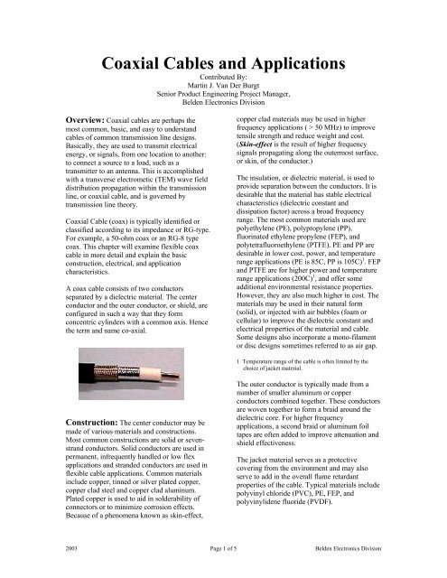
<strong>Coaxial</strong> <strong>Cables</strong> <strong>and</strong> <strong>Applications</strong>Contributed By:Martin J. Van Der BurgtSenior Product Engineering Project Manager,Belden Electronics DivisionOverview: <strong>Coaxial</strong> cables are perhaps themost common, basic, <strong>and</strong> easy to underst<strong>and</strong>cables of common transmission line designs.Basically, they are used to transmit electricalenergy, or signals, from one location to another:to connect a source to a load, such as atransmitter to an antenna. This is accomplishedwith a transverse electrometic (TEM) wave fielddistribution propagation within the transmissionline, or coaxial cable, <strong>and</strong> is governed bytransmission line theory.<strong>Coaxial</strong> Cable (coax) is typically identified orclassified according to its impedance or RG-type.For example, a 50-ohm coax or an RG-8 typecoax. This chapter will examine flexible coaxcable in more detail <strong>and</strong> explain the basicconstruction, electrical, <strong>and</strong> applicationcharacteristics.A coax cable consists of two conductorsseparated by a dielectric material. The centerconductor <strong>and</strong> the outer conductor, or shield, areconfigured in such a way that they formconcentric cylinders with a common axis. Hencethe term <strong>and</strong> name co-axial.copper clad materials may be used in higherfrequency applications ( > 50 MHz) to improvetensile strength <strong>and</strong> reduce weight <strong>and</strong> cost.(Skin-effect is the result of higher frequencysignals propagating along the outermost surface,or skin, of the conductor.)The insulation, or dielectric material, is used toprovide separation between the conductors. It isdesirable that the material has stable electricalcharacteristics (dielectric constant <strong>and</strong>dissipation factor) across a broad frequencyrange. The most common materials used arepolyethylene (PE), polypropylene (PP),fluorinated ethylene propylene (FEP), <strong>and</strong>polytetrafluoroethylene (PTFE). PE <strong>and</strong> PP aredesirable in lower cost, power, <strong>and</strong> temperaturerange applications (PE is 85C, PP is 105C) 1 . FEP<strong>and</strong> PTFE are for higher power <strong>and</strong> temperaturerange applications (200C) 1 , <strong>and</strong> offer someadditional environmental resistance properties.However, they are also much higher in cost. Thematerials may be used in their natural form(solid), or injected with air bubbles (foam orcellular) to improve the dielectric constant <strong>and</strong>electrical properties of the material <strong>and</strong> cable.Some designs also incorporate a mono-filamentor disc designs sometimes referred to as air gap.1 Temperature range of the cable is often limited by thechoice of jacket material.Construction: The center conductor may bemade of various materials <strong>and</strong> constructions.Most common constructions are solid or sevenstr<strong>and</strong>conductors. Solid conductors are used inpermanent, infrequently h<strong>and</strong>led or low flexapplications <strong>and</strong> str<strong>and</strong>ed conductors are used inflexible cable applications. Common materialsinclude copper, tinned or silver plated copper,copper clad steel <strong>and</strong> copper clad aluminum.Plated copper is used to aid in solderability ofconnectors or to minimize corrosion effects.Because of a phenomena known as skin-effect,The outer conductor is typically made from anumber of smaller aluminum or copperconductors combined together. These conductorsare woven together to form a braid around thedielectric core. For higher frequencyapplications, a second braid or aluminum foiltapes are often added to improve attenuation <strong>and</strong>shield effectiveness.The jacket material serves as a protectivecovering from the environment <strong>and</strong> may alsoserve to add in the overall flame retardantproperties of the cable. Typical materials includepolyvinyl chloride (PVC), PE, FEP, <strong>and</strong>polyvinylidene fluoride (PVDF).2003 Page 1 of 5 Belden Electronics Division
permanent install <strong>and</strong> flex radius is for flexing.Flex radius should not be misunderstood to meanthat the cable is designed for continuous flexing.Pulling Tension is the maximum load bearingweight for the cable. It is typically a safe valuewell below the break strength of the cable.Staying below this maximum assures that theconductor will not be stretched resulting inelectrical performance problems in the cable.<strong>Applications</strong>: One of the broadest uses ofcoaxial cable is for video distribution. FromCATV signals around the neighborhood toprecision digital signals in a post-productionstudio, these signals are routed on 75 ohmcoaxial cable. Broadb<strong>and</strong> CATV (or MATV)signals typically use a series 59 (RG-59) orseries 6 (RG-6) type coaxial cable, or drop cable.These cables use copper covered steelconductors <strong>and</strong> aluminum foil/braid combinationshields (outer conductors). They are designed foruse above 50 MHz, with high strength, lowweight <strong>and</strong> low cost the primary factors. Thesecables are all typically designed to a SCTEst<strong>and</strong>ard <strong>and</strong> are a commodity-type item.Electrical performance is good <strong>and</strong> clearlydefined in the industry st<strong>and</strong>ards. <strong>Cables</strong> used inoutdoor environments typically utilize apolyethylene jacket material. The distributiontrunk cable is series 11 (RG-11) type or larger –typically “hard line” cable utilizing a corrugatedcopper outer conductor. These cables aredesigned for minimum attenuation <strong>and</strong> goodpower h<strong>and</strong>ling capability.Another type of 75 ohm video cable is st<strong>and</strong>ardvideo cable. These cables are based uponst<strong>and</strong>ard RG-type designs, utilizing coppercovered steel, copper, or tinned copperconductors <strong>and</strong> bare or tinned copper braid onlyshields. This cable is used primarily for CCTV,security, surveillance, <strong>and</strong> other “non-critical”video applications – video for consumption thatwill not be manipulated, saved, or used for otherpurposes. These cables are not typicallyassociated with an industry st<strong>and</strong>ard, so there ismuch variation <strong>and</strong> differentiation amongavailable designs. Typical cables specifynominal electrical values only.The high end of video cables is precision videocable. These cables are loosely based upon thest<strong>and</strong>ard RG-type designs. They have solid barecopper conductors, foam dielectric, combinationfoil <strong>and</strong> 95% tinned copper braid shields. Theyare designed for maximum b<strong>and</strong>width, minimumreturn loss, <strong>and</strong> minimum attenuation loss. Thecables have very tight requirements on allelectrical attributes <strong>and</strong> are used for both analog<strong>and</strong> digital video in broadcast, post-production,<strong>and</strong> other critical video applications.There are also many specialty types of videocables, such as S-VHS, RGB, DBS, <strong>and</strong> Triax toname a few.<strong>Cables</strong> used for two-way communication, RF<strong>and</strong> microwave transmission, data transmission<strong>and</strong> instrumentation/control are typically 50 ohmcoaxial cables. These cables are based uponMIL-Spec designs <strong>and</strong> are most often referred toby their RG type number. The cables fall into afew categories: Transmission <strong>and</strong> computercables that are based upon RG type designs, butnot per the current MIL-Spec; MIL-C-17 QPLcables that are in compliance with the currentMIL-Spec; <strong>and</strong> low-loss cables based looselyupon RG type designs. The RG type cables arethe most used products since the majority ofcable applications do not require QPL cables.Furthermore, most manufacturers have a limitedavailability of QPL cables for this reason. Themajor differences between the cables aretypically the type of PVC jacket material used<strong>and</strong> less stringent electrical <strong>and</strong> physicalrequirements. For wireless <strong>and</strong> antennaapplications, the low-loss cables are gainingpopularity because of their size, weight, cost, <strong>and</strong>performance advantages over the traditionaldesigns. These cables typically utilize a foameddielectric material <strong>and</strong> combination foil/braidshields.Other impedance cables are used for datatransmission <strong>and</strong> instrumentation/control. Theseare typically 93 ohm or 125 ohm <strong>and</strong> are not ascommon as they once were. As with thetransmission <strong>and</strong> computer cables, the majorityof cables used are RG type cables with minimaluse of QPL product.Specialty coaxial cables include low-noise <strong>and</strong>musical interconnects cables. These arespecially designed to minimize piezoelectric <strong>and</strong>triboelectric noise in cables <strong>and</strong> are not for RFuse. The cables may be loosely based upon RGtype designs, but utilize semi-conductivematerial layers within the cable.2003 Page 4 of 5 Belden Electronics Division
Conclusion:Hopefully this chapter has given you a briefoverview of coaxial cable <strong>and</strong> a better insight tothe relevant design properties. When choosing acable for your application, work backwards fromthe end-need requirements. What is the specificapplication? Do you know what impedance isrequired? What is the frequency of interest?What is the loss budget (how much cableattenuation loss is allowed)? How long is thecable run length? Indoor or outdoor? Are thereagency requirements (UL, NEC, AWM, MIL-Spec, etc.)? What connector type will be used?These few questions should help you easilyidentify an appropriate coaxial cable.Martin J. Van Der BurgtMarty is a Senior Product Engineering ProjectManager for Belden Electronics Division. Hisexperience encompasses project management<strong>and</strong> product development positions. Hecurrently has responsibility for all design <strong>and</strong>development efforts, <strong>and</strong> manages the day-to-dayactivity of product engineers, for Belden’sentertainment, service provider, <strong>and</strong> industrialproduct market areas, <strong>and</strong> has recently filed anapplication for his first patent. Marty receivedhis Bachelor of Science Degree in ElectricalEngineering (BSEE) from Marquette University,Milwaukee, WI in 1992 <strong>and</strong> has been withBelden since that time. He is a member ofseveral professional organizations <strong>and</strong> st<strong>and</strong>ardsbodies, <strong>and</strong> has had several articles onAudio/Video <strong>and</strong> RF topics published in trademagazines <strong>and</strong> journals. Most recently, coauthoredtutorials on “High-Definition Cabling<strong>and</strong> Return Loss” in the January 2001 SMPTEJournal <strong>and</strong> “Impedance” in the 2002 NABBroadcast Engineering Conference Proceedings.Marty also holds a FCC Amateur Extra Classamateur radio license. He <strong>and</strong> his wife Beth livein Richmond, IN.Marty Van Der Burgt2003 Page 5 of 5 Belden Electronics Division