induction heating of different shaped tubes - ATE Applicazioni ...
induction heating of different shaped tubes - ATE Applicazioni ...
induction heating of different shaped tubes - ATE Applicazioni ...

Create successful ePaper yourself
Turn your PDF publications into a flip-book with our unique Google optimized e-Paper software.
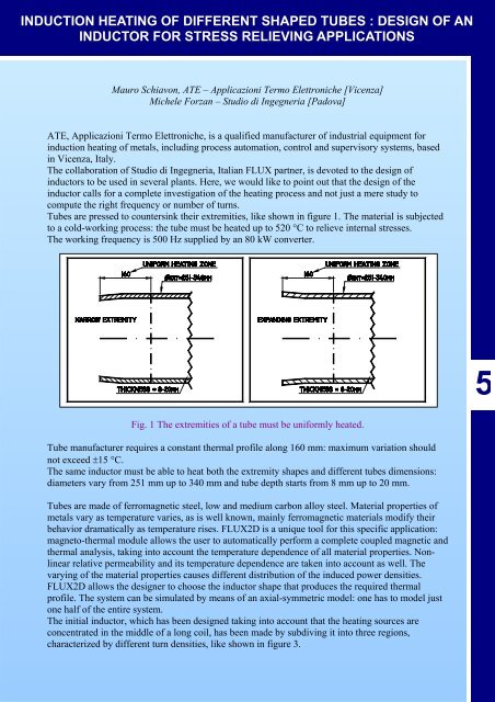
INDUCTION HEATING OF DIFFERENT SHAPED TUBES : DESIGN OF ANINDUCTOR FOR STRESS RELIEVING APPLICATIONSMauro Schiavon, <strong>ATE</strong> – <strong>Applicazioni</strong> Termo Elettroniche [Vicenza]Michele Forzan – Studio di Ingegneria [Padova]<strong>ATE</strong>, <strong>Applicazioni</strong> Termo Elettroniche, is a qualified manufacturer <strong>of</strong> industrial equipment for<strong>induction</strong> <strong>heating</strong> <strong>of</strong> metals, including process automation, control and supervisory systems, basedin Vicenza, Italy.The collaboration <strong>of</strong> Studio di Ingegneria, Italian FLUX partner, is devoted to the design <strong>of</strong>inductors to be used in several plants. Here, we would like to point out that the design <strong>of</strong> theinductor calls for a complete investigation <strong>of</strong> the <strong>heating</strong> process and not just a mere study tocompute the right frequency or number <strong>of</strong> turns.Tubes are pressed to countersink their extremities, like shown in figure 1. The material is subjectedto a cold-working process: the tube must be heated up to 520 °C to relieve internal stresses.The working frequency is 500 Hz supplied by an 80 kW converter.5Fig. 1 The extremities <strong>of</strong> a tube must be uniformly heated.Tube manufacturer requires a constant thermal pr<strong>of</strong>ile along 160 mm: maximum variation shouldnot exceed ±15 °C.The same inductor must be able to heat both the extremity shapes and <strong>different</strong> <strong>tubes</strong> dimensions:diameters vary from 251 mm up to 340 mm and tube depth starts from 8 mm up to 20 mm.Tubes are made <strong>of</strong> ferromagnetic steel, low and medium carbon alloy steel. Material properties <strong>of</strong>metals vary as temperature varies, as is well known, mainly ferromagnetic materials modify theirbehavior dramatically as temperature rises. FLUX2D is a unique tool for this specific application:magneto-thermal module allows the user to automatically perform a complete coupled magnetic andthermal analysis, taking into account the temperature dependence <strong>of</strong> all material properties. Nonlinearrelative permeability and its temperature dependence are taken into account as well. Thevarying <strong>of</strong> the material properties causes <strong>different</strong> distribution <strong>of</strong> the induced power densities.FLUX2D allows the designer to choose the inductor shape that produces the required thermalpr<strong>of</strong>ile. The system can be simulated by means <strong>of</strong> an axial-symmetric model: one has to model justone half <strong>of</strong> the entire system.The initial inductor, which has been designed taking into account that the <strong>heating</strong> sources areconcentrated in the middle <strong>of</strong> a long coil, has been made by subdiving it into three regions,characterized by <strong>different</strong> turn densities, like shown in figure 3.
INDUCTION HEATING OF DIFFERENT SHAPED TUBES : DESIGN OF ANINDUCTOR FOR STRESS RELIEVING APPLICATIONSThe inductor has been modified several times in order to reach the required performance: forexample, the inductor, shown in fig. 6, has two <strong>different</strong> internal radiuses.Finally, the most efficient inductor is the one shown in figure 9.Zone 3:10 turnsZone 2:8 turnsZone 1:11 turnsFig. 3 – The initial inductor. Infigure, the model representsjust one half <strong>of</strong> entire system.Zone 3:9 turnsFig. 4 - Equiflux isovalues.Fig. 5 – Thermal pr<strong>of</strong>ile on thesurface. Temperature differencesare too high [420 °C – 485 °C].Line path starts from the bottom<strong>of</strong> the tube.5Zone 3:7 turnsZone 1:11 turnsFig. 6 – Another inductorsimulated.Fig. 7 - Equiflux isovalues.Fig. 8 – Thermal pr<strong>of</strong>ile on thesurface. Temperature distributionhas been improved, butdifferences are still too high [420°C – 470 °C]. This solution hasbeen dropped becausetemperature pr<strong>of</strong>ile has beenimproved only when the narrowextremity is heated.22 / 6
INDUCTION HEATING OF DIFFERENT SHAPED TUBES : DESIGN OF ANINDUCTOR FOR STRESS RELIEVING APPLICATIONSZone 3:10 turnsZone 2:no turnZone 1:13 turnsFig. 9 – The final inductor.Fig. 10 - Equiflux isovalues.Fig. 11 – Thermal pr<strong>of</strong>ile on thesurface. Temperature differencesare now very low [447 – 475°C].The same inductor designed for the narrow extremity must be used to heat the other wider end.Simulations have been devoted to find out the best position <strong>of</strong> the tube inside the inductor.Initial position <strong>of</strong> the workpiece is shown in figure 12, where the tube is positioned completelyinside the inductor. The consequently <strong>heating</strong> process leads to a non uniform thermal pr<strong>of</strong>ile.One can improve the temperature the temperature distribution by moving the tube upwards, seen infig. 15 – 18.533 / 6
INDUCTION HEATING OF DIFFERENT SHAPED TUBES : DESIGN OF ANINDUCTOR FOR STRESS RELIEVING APPLICATIONSFig. 12 – The inductor designedfor the narrow end now heats theexpanding extremity.Fig. 13 – Equiflux isovalues.Fig. 14 – Thermal pr<strong>of</strong>ile on thesurface. Temperaturedifferences are too high [420 °C– 500 °C].5Fig. 17 – Temperaturedifferences are significantlyreduced [410 – 460 °C].Fig. 15 – The tube position hasbeen modified to improve thetemperature uniformity.Fig. 16 – Equiflux isovalues.44 / 6
INDUCTION HEATING OF DIFFERENT SHAPED TUBES : DESIGN OF ANINDUCTOR FOR STRESS RELIEVING APPLICATIONSFig. 20 – Temperaturedifferences are now acceptable[424 – 458 °C].Fig. 18 – The final position <strong>of</strong> theexpanding tube.Fig. 19 – Equiflux isovalues.Measurements have been performed on both the extremities; demonstrating that the requiredtemperature is achieved with an error even lower than the one computed (+/- 10 °C).5fig. 21 – <strong>ATE</strong> <strong>induction</strong> equipment for stress relieving <strong>of</strong> steel <strong>tubes</strong>, installed in Dalmine works -Bergamo.55 / 6
6 / 6INDUCTION HEATING OF DIFFERENT SHAPED TUBES : DESIGN OF ANINDUCTOR FOR STRESS RELIEVING APPLICATIONSFLUX2D magneto-thermal module is a powerful tool aiding in the design <strong>of</strong> <strong>induction</strong>-<strong>heating</strong>equipment.It reduces the cost for the design, because one does not need to build several <strong>different</strong> inductors todiscover which is the optimum solution. A deeper knowledge <strong>of</strong> the process also allows thedesigner to carry out modifies required to improve the characteristics <strong>of</strong> the system.Finally, we would like to point out that a two dimensional model is necessary to describe an ‘edge’problem similar to the one previously discussed and the fact that the model must consider non linearproperties <strong>of</strong> materials.56