GdEngine managementModel: 406 2,lD Turbo 605 2,lD Turbo 806D 2,l TurboPEUGEOTProbable cause340 I Air conditioning I Wiring, AC compressor clutch relay, AC control module, ECM350Glow plug control module - pre-/post-heatcontrol361 I Tachometer signal 1 Wiring, tachometer, ECM363 I Fuel consumption signal 1 Wiring, trip computer, ECM600601Fuel injection pump - rotor positionmonitoringFuel injection pump - rotor positiont. .Wiring, glow plug control module, ECM602 1 Fuel injection pump - rotor calibration I Wiring, fuel injection pump, ECM603604605650Fuel injection pump - rotor minimumcalibrationFuel deliveryheedle lift signalWiring, fuel system, fuel qantity adjuster, fuel injectionpump, relay module, ECMWiring, shield wiring, injection pump cam ring positionsensor, injection pump rotor position sensor, fuel injectionDumD. ECM700 Fuel injection pump - cam position Wiring, fuel injection timing solenoid, fuel injection pump,monitorinarelav module. ECM701702Fuel injection pump - delivery calibrationFuel shut-off solenoidFuel injection pump - cam ring positionsensorFuel injection pump - cam ring calibrationFuel injection pumpWiring, fuel injection pump, ECMWiring, injection pump calibration resistor, fuel injectionpump, ECMWiring, relay module, coded keypad, fuel shut-off solenoid,fuel injection pump, ECMWiring, injection pump cam ring position sensor, fueltemperature sensor, fuel injection pump, ECMWiring, fuel injection pump, ECM703 I Fuel injection pump - timing control I Fuel injection pump timing, CKP sensor750 1 Injector needle lift sensor - no signal I Wiring, injector needle lift sensor, fuel system, injector, ECM751 I Injector needle lift sensor - incorrect signal I Wiring, injector needle lift sensor, fuel system, injector, ECM803Exhaust gas recirculation (EGR) solenoid -incorrect signalWiring, relay module, EGR solenoid, ECM[AutodataEna~ne rnanaaernent505
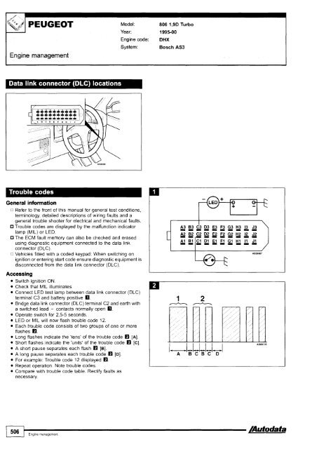
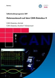
PEUGEOT Model: 806 1,9D TurboYear: 1995-00I Engine managementEngine code:System:DHXBosch AS3General informationo Refer to the front of this manual for general test conditions,terminology, detailed descriptions of wiring faults and ageneral trouble shooter for electrical and mechanical faults.<strong>Trouble</strong> codes are displayed by the malfunction indicatorlamp (MIL) or LED.The ECM fault memory can also be checked and erasedusing diagnostic equipment connected to the data linkconnector (DLC).o Vehicles fitted with a coded keypad: When switching onignition or entering start code ensure diagnostic equipment isdisconnected from the data link connector (DLC).AccessingSwitch ignition ON.Check that MIL illuminates.Connect LED test lamp between data link connector (DLC)terminal C3 and battery positive m.Bridge data link connector (DLC) terminal C2 and earth witha switched lead - contacts normally open m.Operate switch for 2,545 seconds.LED or MIL will now flash trouble code 12.Each trouble code consists of two groups of one or moreflashes O.Long flashes indicate the 'tens' of the trouble code rn [A].Short flashes indicate the 'units' of the trouble code rn [C].A short pause separates each flash rn [B].A long pause separates each trouble code rn [Dl.For example: <strong>Trouble</strong> code 12 displayed rn.Repeat operation. Note trouble codes.Compare with trouble code table. Rectify faults asnecessary.
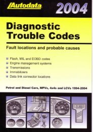
- Page 1: DiagnosticTrouble GodesFault locati
- Page 5 and 6: 1 PEUGEOTModel: I06 1,011,111,311,4
- Page 7 and 8: Erasing Method 2Ensure ignition swi
- Page 9 and 10: Engine managementModel: 106 1,011,1
- Page 12 and 13: IModel: 106 1 ,311,6 406 1,812,O 60
- Page 14 and 15: Model: 106 1,311,6 406 1,812,O 605
- Page 16 and 17: EOBDtypePI152PI157PI158PI186Fault l
- Page 18 and 19: Engine managementTrouble code ident
- Page 20 and 21: 7Engine managementTrouble code iden
- Page 22 and 23: Model: 406 2,lD Turbo 605 2,lD Turb