Using Passive Loop Antennas - DXing.info
Using Passive Loop Antennas - DXing.info
Using Passive Loop Antennas - DXing.info

Create successful ePaper yourself
Turn your PDF publications into a flip-book with our unique Google optimized e-Paper software.
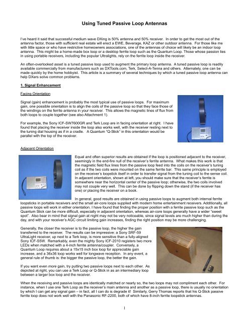
<strong>Using</strong> Tuned <strong>Passive</strong> <strong>Loop</strong> <strong>Antennas</strong>I’ve heard it said that successful medium wave <strong>DXing</strong> is 50% antenna and 50% receiver. In order to get the most out of theantenna factor, those with sufficient real estate will erect a EWE, Beverage, KAZ or other outdoor antenna. For those like mewith little space or who have restrictive homeowners associations, one of the antennas of choice will likely be an indoor loopantenna. This might be a home-made box loop or a desktop ferrite loop such as the Quantum <strong>Loop</strong>. Those whose passion liesin using portable receivers, including the popular Ultralights, rely on the ferrite loop inside the receiver.An often-overlooked asset is a tuned passive loop used to augment the primary loop antenna. A tuned passive loop is readilyavailable commercially from manufacturers such as DXTools.com, Terk, Select-A-Tenna and others. Alternately, one can bemade quickly by the home hobbyist. This article is a summary of several techniques by which a tuned passive loop antenna canhelp DXers solve common problems.1. Signal EnhancementFacing OrientationSignal (gain) enhancement is probably the most typical use of passive loops. For maximumgain, one possible orientation is to align the coils of the passive loop so that they face those ofthe windings on the ferrite antenna in your receiver. This allows the magnetic lines of flux fromboth loops to couple together (see also Attachment 1).For example, the Sony ICF-SW7600GR and Terk <strong>Loop</strong> are in facing orientation at right. I havefound that placing the receiver inside the loop also works well, with the receiver resting next tothe tuning dial housing as if in a cradle. A Quantum “Q-Stick” in this orientation would beparallel with the top of the receiver.Adjacent OrientationEqual and often superior results are obtained if the loop is positioned adjacent to the receiver,seemingly in the end-fire null of the receiver’s ferrite antenna. What makes this work is thatthe magnetic field flux lines from the passive loop feed into the coils on the receiver’s tuningcoil as if the two coils were mounted on the same ferrite bar. This same principle is employedon the receiver’s loopstick itself in order to transfer signal from the tuning coil to the sense coil.In adjacent orientation, shown at left, you should make sure that the receiver’s ferrite issomewhere near the horizontal center of the passive loop; otherwise, the two coils involvedmay not couple very well. This can be done by flipping down the stand (if the receiver hasone) or placing the receiver on a book.In general, good results are obtained in using passive loops to augment both internal ferriteloopsticks in portable receivers and the small air-core loops supplied with modern home entertainment receivers. Additionally, allpassive loops will work in either orientation. I have found that finding the proper position with a ferrite passive loop such as theQuantum Stick can be more difficult, especially in adjacent orientation, whereas air-core loops generally have a wider “sweetspot”. Also bear in mind that signal gain at night may not be very noticeable, since signal levels are much higher than during theday, and with your receiver’s AGC circuit limiting gain increases, finding the right position may be more challenging.Generally, the closer the receiver is to the passive loop, the higher the gaintransferred to the receiver. The results can be impressive: a Sony SRF-59UltraLight receiver, up next to a Terk loop, is more sensitive than a fully-alignedSony ICF-S5W. Remarkably, even the mighty Sony ICF-2010 registers two moreLEDs when matched with a 4-inch ferrite antenna/coupler. Conversely, aQuantum <strong>Loop</strong> requires about a 15x15 inch box loop for appreciable gainincrease, and a 36x36 loop works well for longwave reception. In any event, ageneral rule of thumb is: the bigger the passive loop, the better the gain.If you want even more gain, try putting two passive loops next to each other. Asdepicted at right, you can use a Terk <strong>Loop</strong> or Q-Stick in as an intermediary loopbetween a larger box loop and the receiver.When the receiving and passive loops are identically matched or nearly so, the two loops may not compliment each other. Forinstance, when I use one Terk <strong>Loop</strong> as the receiver’s main antenna and another as a passive loop, there is usually no orientationby which I can get any signal gain – in fact, all I can do is degrade it! Similarly, Gerry Thomas reports that his Q-Stick passiveferrite loop does not work well with the Panasonic RF-2200, both of which have 8-inch ferrite loopstick antennas.1
2. Selectivity EnhancementCritical SpacingA technique to increase the selectivity of the receiver consists of simply pulling the receiver away from the passive loop in eitherorientation. At a critical point, the loop will still be close enough to provide signal gain, but the high-frequency content andadjacent-channel interference are reduced. Electrically, the two coils are now decoupled to a large degree. With the SonyM37V, the critical point is about 3 inches away from a Terk <strong>Loop</strong> and about 10 inches away from a 15x15 inch box loop. With areceiver employing a larger ferrite loopstick, the critical distance will be further away.By simulating the resultant loopstick/passive loop circuit on Gene Preston’s AC.EXE program (see Attachment 1 for moredetails), the results of a typical critically-spaced coupling are shown below:Critical Spacing Selectivitydb0-2-4-6-8-10950 975 986 988 990 992 994 996 998 1000 1002 1004 1006 1008 1010 1012 1025 1050FrequencyIn this graph, the signal is decreased about 6 decibels at 3.5 kHz on either side of the desired frequency, making this roughlyequivalent to a 7 kHz filter. Compared to the filtering in many portable receivers, this can be a major improvement. Continuingto separate the receiver and loop will narrow this figure even more. However, past a certain point, the two will be decoupled tosuch a degree that the passive loop no longer will affect the selectivity. Also, if your receiver has decent IF filtering, or if thepassive loop has very low Q, the effects of this strategy may be negligible.You can also experiment with using more than one passive loop. For instance, I findsuccess putting an intermediate loop such as the Q-Stick near the receiver for gainenhancement in addition to a much larger passive loop for selectivity control. As isshown in the picture on the right, the intermediate loop is pulled away just a bit, whichhelps to further tighten the selectivity.The reverse of this selectivity control strategy is also generally true, in that if youplace the receiver quite close to the passive loop, this will generally result in abroadening of the bandwidth. This is more pronounced with a larger passive loop. Ata certain point, though, the receiver and passive loop will be too close together. Inthat case, the two coils will start to decouple, and tuning of the passive loop will not significantly affect the receiver.Detuning of the <strong>Passive</strong> <strong>Loop</strong>Critical AngleAn alternate way to decouple the receiver and passive loop is to place them atapproximately a 45 degree angle to each other. By doing so, the coils are in neither facingnor adjacent orientation, but rather half-way in between. At this point, the two arecompletely decoupled, regardless of the actual distance between them. To find this point,place the receiver and passive loop in this orientation and move the receiver or loop untilyou find a point at which tuning the passive loop has no effect on the receiver. You canthen move the loop or receiver anywhere along an imaginary 45 degree line, and the twounits will remain decoupled. Selecting a point just on either side of the imaginary 45degree line will begin to loosely couple the receiver and loop in one orientation or the other,and the receiver’s bandwidth will be narrowed as with critically-spaced decoupling. This isoften more convenient with receivers with large loopstick antennas, since the distancerequired for critical spacing is often correspondingly quite large.The tuning of the passive loop will change depending on how far away the receiver is. To verify this, try tuning to a certainfrequency on your receiver, and then tune the passive loop for a peak while the receiver is loosely coupled in facing orientation.Bring the receiver closer and closer to the loop and continue to adjust the tuning of the loop tuning to maintain the peak. Withfacing orientation, you will find that you must tune the loop higher and higher in the band to maintain the peak, and lower andlower with adjacent orientation. Therefore, depending on the technique you are using, slight retuning of the passive loop may berequired.2
3. Adjacent channel notchingYou may have noticed that a passive loop will both peak and notch a particular frequency, depending on the tuning capacitor’ssetting. For instance, try peaking a station at 1000 kHz or so using facing orientation with the loop pulled back a couple ofinches. Then, slowly rotate the passive loop’s tuning capacitor up-band a bit – you should notice a definite notch when thepassive loop is tuned to 1020 kHz or so. In other words, in facing orientation, the passive loop will induce a notch below itstuned frequency! With adjacent orientation, just the opposite occurs – a notch will be placed above the passive loop’s tunedfrequency. In the chart below, the critically-spaced response from earlier is extended down to -25 db to show that there aredefinite notches about 12 khz away in both orientations.Up-band and Down-band Notching0-5-10db-15-20-25950 975 986 988 990 992 994 996 998 1000 1002 1004 1006 1008 1010 1012 1025 1050FrequencyBecause of the way the receiver’s loopstick and the passive loop interact, there will always be a lower notch in facing orientationand an upper notch in adjacent orientation. Therefore, if you want to put a notch up-band from the desired target to attenuateinterference on the neighboring channel, use adjacent orientation, and use facing orientation for notching down-band from yourtarget. As a memory aid, I use the phrase “face down, this side up” to remember the relationships. While not reflected intheoretical calculations, in actual practice there is a more pronounced notch in adjacent orientation.As an example of using this technique, I have a strong local on 1000 kHz which makes reception of 990 and 1010 a challenge.In facing orientation (down-band notch) I can listen to 1010 much more easily, and the same for 990 using adjacent orientation(up-band notch). If I get the orientation wrong, as the chart above shows, the interference is 20 decibels worse than when Istarted!Notch Depth vs. Notch/Peak SpreadAs you decouple the receiver and passive loop, in addition to tightening the selectivity, the “spread” between peak and notch willnarrow. The graph below shows the effect of progressively decoupling the receiver and loop.Notch Depth vs. Notch/Peak Spread0-5-10db-15-20-25950 975 986 988 990 992 994 996 998 1000 1002 1004 1006 1008 1010 1012 1025 1050FrequencyThe trade-off here is that not only does decoupling decrease the gain imparted to the receiver, the depth of the notch getsshallower as well. As with the critically-spaced selectivity technique above, an intermediary loop between the main passive loopand the receiver will help restore gain should you need it.Notching an Interfering StationFor the DXer, the optimum situation is where the peak and notch are spread exactly 9 or 10 kHz apart (and even narrower fortransoceanic split-frequency <strong>DXing</strong>) so that the target is peaked and the interfering station is notched. A casual placement of theloop and receiver may result in a 20-30 kHz spread, and a critically-placed loop for selectivity alone might still put the notch up to15 kHz away from the peak.3
By moving the receiver even further away from the loop, the spread between peak and notch decreases, and at a critical point,the spread will be exactly 10 kHz. The spacing will depend on the receiver and passive loop being used. For instance, with aSony M37V and a 15x15-inch box loop, the distance is usually around 12 inches with either orientation. You will need toexperiment to find the distance that works for each receiver/loop combination, and the distance in one orientation may bedifferent than the other. As above, the use of an intermediary loop can help provide extra gain if needed.A recommended approach to find the critical placement for a 9 or 10 kHz spread is as follows:1. Select the orientation based on where the co-channel interference is (i.e., adjacent orientation for upper notch andfacing orientation for lower notch).2. Tune the desired target frequency on both the receiver and loop for maximum gain, with the receiver a few inches awayfrom the loop.3. Tune to the interfering frequency on the receiver without touching the tuning on the passive loop.4. Move the receiver either closer to or away from the loop along the imaginary perpendicular line until the notch on theinterfering station is found; it may disappear or perhaps the background noise will elevate. If you have troublediscerning any notch effect, try orienting the receiver and passive loop to place a simple directional null on theinterfering station so that you can better hear the notch.5. If you end up moving the receiver further away from the loop in Step 4 to minimize the interfering station, that meansyou started out too close in the first place. Similarly, moving the receiver closer to the loop for the notch means youstarted out too far away. In either case, come a little bit back towards where you started and repeat steps 2-4 until thetarget peak and interference notch coincide.For example, in order to receive a semi-local on 620 kHz under a strong local on 630 kHz:1. Select adjacent orientation to put a notch above the desired target.2. Tune the receiver to 620 and place the receiver several inches away from the loop, then find the peak on the loop. Forthis example, assume the initial distance is 14 inches away.3. Tune the receiver to 630 (the interfering station).4. Move the receiver either closer to or farther from the receiver to find the notch. For this example, assume that thereceiver is moved closer, to 10 inches away, for the notch on 630.5. This means that the distance was too great to begin with, so come back a little towards the original distance (say, to 11inches away) and retune both receiver and loop for a peak on 620. If repeating steps 3 and 4 shows that no furthermovement is required, the desired 10 kHz spread has been found.Notching out split-frequency interference is much easier. In this case there will generally be a heterodyne as an indicator, soyou don’t need to actually tune to the interfering station in Step 3. Rather, adjust the tuning on the loop to minimize/notch theheterodyne while tuned to the desired target, and then increase or decrease the distance between the receiver and loop(followed by slight retuning of the loop) until you find the position of maximum clarity of the target and minimum heterodyning.This becomes a very quick process with a little practice. In many case, notching of the interfering carrier will cause thereceiver’s AGC to increase gain for the target, resulting in an apparent increase in sensitivity.Once you have found the desired notch, depending on the situation you can then:• Move the receiver or loop a little, either closer to or further away, to see if there is a better relative position, rather thantrying to fine-tune the loop’s tuning• Retune the loop slightly away from the interfering station (e.g., tune the loop slightly down-band when listening to 620under a local on 630) while keeping the distance between the receiver and loop the same. This will maintain the 10kHz spread, but will put the peak on the target’s sideband which is furthest away from the interference and the notch onthe closest interfering sideband.• Move the receiver a little closer to the loop in order to increase the peak/notch spread (say, to about a 12 kHz spreadfor domestic <strong>DXing</strong>) and then retune the loop slightly to the point of best clarity. The result is that you will peak thesideband of the target which is away from the pest while keeping the notch on the carrier of the interfering station.Dealing with IBOC Digital NoiseOne variation to the orientation rule above is in dealing with IBOC noise. This stems from the fact that the digital sidebandswhich produce the noise are centered about 12 kHz away on either side of the station’s actual carrier frequency. For example, ifmy 630 kHz local were using IBOC, the digital noise would be centered at 618 and 642. Therefore, to tune in 620, one mustactually use facing orientation to put a notch below on 618, even though the interfering station itself is above on 630.Of course, by doing so, the analog sidebands from the main signal on 630 will cause interference, although the decoupledpassive loop may provide increased selectivity in addition to the notch. In any event, my experience has been that notching outthe noise associated with IBOC broadcasts results in a more readable signal, especially with weak DX targets that wouldotherwise be completely buried in the noise. Unfortunately, if there is an IBOC station on the other side as well (in this case on610, with the upper digital sideband on 622), then there isn’t much that can be done, since both sidebands of the target on 620would suffer from the noise.4
Notch Depth and QThe “Q” of a passive loop, which essentially describes the tuning sharpness of the loop, also influences the peaks and notchesachieved. Specifically, both the peak and the notch are more pronounced as the loop’s Q increases: therefore, a higher the Q ofthe loop, the better.Peak/Notch vs. Q0-5-10db-15-20-25950 975 986 988 990 992 994 996 998 1000 1002 1004 1006 1008 1010 1012 1025 1050FrequencyLow QvvHigh QWhile the above graph depicts results from using the high-Q loop in facing orientation,the principle applies in either orientation. For example, to listen to 1200-WOAI some1750 miles away on a Sony M37V, I need to deal with IBOC noise from a strong semilocalon 1190 and a strong local on 1210. <strong>Using</strong> the IBOC strategy above, I must useadjacent orientation to avoid 1190’s upper digital sideband on 1202. Favoring the lowersideband of 1200 in this way, interference from 1210 is reduced, but 1190’s upperanalog sideband will interfere: a tight situation indeed.<strong>Using</strong> a 9-inch Terk loop, I can barely make out 1200-WOAI amidst the various sourcesof interference. With a small (3.5 inch) basket-woven Litz wire loop with very high Q (atright), there is a definite peak of intelligibility: even though the gain isn’t as great as withthe Terk loop, 1200-WOIA comes in just fine!4. Adjacent channel interference – Fixed Channel “Detuning”If your receiver only tunes in fixed 9 or 10 kHz increments, as with many UltraLights and other portables, <strong>DXing</strong> split frequenciescan be difficult. For example, tuning to a trans-oceanic signal on 774 kHz next to a local on 770 would be much easier if youcould slide over to 775 or 776. Such “detuning” is also common practice with domestic stations spaced 10 kHz apart; forinstance, to hear 780 under local 770, you might tune up to 782, placing 12 kHz between you and the problem. In both of thesecases, you will be favoring one sideband over the other in order to avoid interference.The peak/notch technique above can provide considerable help with fixed tuning receivers. It is probably impossible to movethe receiver far enough away to effect a 1 or 2 khz spread between peak and notch. However, you can move the receiver out toa point of extreme tuning sharpness in order to increase the slope of the peak-to-notch curve to the maximum extent possible.In looking at the “Notch Depth vs. Notch/Peak Spread” graph several sections earlier, as the notch draws closer and closer tothe peak, the depth of the notch is more shallow. However, the slope of the line is significantly greater. Therefore, in tightsituations you can take advantage of this steep slope to significantly favor one station, or one sideband, over the other. In doingso, you will either peak the target or notch the adjacent interference; let your ear be the judge.For example, my semi-local on 1190 kHz has substantial man-made interference which renders the lower sideband (centeredaround 1188) completely inaudible, while the upper sideband at 1192 is clean. While my higher-end communications receivercan simply be placed in USB mode for clean reception, an UltraLight with only fixed-tuning AM (dual sideband) mode receivesboth sidebands, and the overall result is an unintelligible signal. <strong>Using</strong> well-separated facing orientation to favor the uppersideband over the lower, I can first tune the loop for a peak on the interference (so I know where I’m at), then tune slightly upbandto notch out the noise. While not necessarily isolating the desired sideband, it is now emphasized in the receiver’spassband compared to the other sideband.But wait, there’s more! By using a second passive loop as an intermediate, the results are even better. In my test on 1190 khzabove, I started out with a Sony ICF-SW7600GR receiver and a 15x15 inch box loop. Separating the two units enough toincrease the slope of the peak-to-notch curve meant that signal gain was rather low. By first placing a tuned Q-Stick in betweenthe units, about 1 inch away from the receiver, I was able to provide more gain to the receiver. The intermediate loop alsofurther enhanced the rejection of the lower sideband – tuning on the box loop was much sharper, corresponding to an evensteeper peak/notch slope. As a result, the upper sideband of 1190 was loud and clear with just a hint of the noise from the lowersideband. While this is not actual exalted carrier single sideband (ECSS) reception which eliminates the offending sidebandaltogether, it is probably about as good as you can do with an AM-only receiver, and it can make a huge difference.5
This can be a valuable strategy even if your receiver is able to tune off-channel. For example, on a recent DXpedition I used anEton e100 UltraLight in Alaska to listen to Asian split-frequency stations. The e100 not only tunes in 1 kHz increments, but alsohas surprisingly tight filtering. However, in situations such as an Asian on 972 kHz next to a domestic on 970, the e100 was notable to produce decent audio, even if I tuned up to 974. <strong>Using</strong> a Terk <strong>Loop</strong> in loosely-coupled facing orientation, I was able tonot only provide extra gain, but also strongly attenuate the domestic on 970. By thus favoring the upper sideband of the targeton 972, it came in loud and clear.5. Co-channel interference – <strong>Passive</strong> PhasingWhen a passive loop is oriented such that its signal for a given station is precisely out ofphase with the signal generated by the receiver’s antenna, the two will cancel each otherout. As a result, an otherwise dominant station will delightfully disappear, allowing you tohear what was lurking underneath. This technique produces a reception pattern in theshape of a cardioid (right), with a pronounced null in one quadrant and virtuallyundiminished reception in the other three.Either orientation can be used for passive phasing, although adjacent orientation oftenseems to work better than facing orientation. Here is a basic procedure for passivephasing (paraphrased from Gerry Thomas’ Q-Stick phasing procedure):1. Tune the passive loop to maximize the frequency of interest using the selectedorientation, then set it well away from the receiver.2. Orient the receiver to place a simple null on the station to be eliminated. Ifpossible, tilt the radio up or down (i.e., azimuth change) to get an even better null,using a tripod for stability if desired.3. With the passive loop still tuned to the desired frequency, position it a few inches away from the receiver. Then, beginrotating it about its vertical axis as you also change the distance from the receiver. At a certain distance and angle, youwill hear the unwanted station’s signal level go down, or see it on the S-meter of the receiver. If you don’t have an S-meter, try decreasing RF gain so that you can better hear the null.4. Once you have found the general distance and angle, try going off-axis a bit (i.e., not at a 90-degree angle from thereceiver) to see if there is an even better orientation of the loop, or try the other orientation. Some phased nulls may befound with the loop at nearly a 45-degree angle from the receiver. Elevating the passive loop an inch or two may makea big difference. Also, with adjacent orientation, the passive loop might have to be tuned slightly up-band to account fordecreased coupling; facing orientation may require re-tuning slightly down-band.5. Once you have found the right distance and angle for the passive loop, slightly adjust the passive loop’s tuning or thereceiver’s position to fine-tune the null.Facing Orientation - Eton e100 and Terk loopAdjacent Orientation - Quantum <strong>Loop</strong> and 15” box loopIf you get a decent directional null in Step 2 above, you may notice that the audio becomes distorted. As a result, the eventualphased null may not be very good because the out-of-phase signal produced by the passive loop is now significantly differentthan the distorted signal produced by the receiver’s directional null. In this case, try to lessen the directional null a bit and thenre-do the phased null.In phasing out the undesired station, the strength of the remaining stations on thatchannel will depend on the levels present in the receiver antenna and passive loopindividually. In other words, the final result will only be as good as the weakestantenna. For example, the M37V has a very small ferrite antenna, and the limitedin-phase signal it produces doesn’t need much opposite-phase signal from thepassive loop to cancel it out; therefore you will have to decouple the loop asignificant amount, resulting in less gain for the DX targets underneath. To remedythis, use an augmenting passive loop for gain, then use a second loop for thephased null – it really works well! In the case of an M37V with a Q-Stick (right), Iam essentially phasing the Terk loop with a receiver with an 8-inch ferrite antenna,so there is sufficient gain to hear the remaining stations.6
With a high-Q passive loop, you may find that its narrower opposite-phase signal doesn’t phase very well with the broadercontribution of the receiver’s loopstick. In such a situation, you can use an intermediate loop with the receiver to narrow itsselectivity, then apply a larger high-Q loop for a phased null. In the picture just above, the opposite occurs: the Q-Stick causesthe receiver component to have a narrower bandwidth than the component supplied by the low-Q Terk loop, so a higher-Qpassive loop would work better in this situation.Once you have nulled the unwanted station to the extent possible, you can then employ a second passive loop and move itaround either the receiver or the first passive loop until you find an even deeper null. This “double phasing” technique can bevery effective, and has allowed me to hear stations under fairly strong locals that would have been impossible with singlepassive phasing alone.Another application for phasing is to reduce co-channel interference. For example, a target on 810 may be sitting alone on thechannel, but a local powerhouse on 820 is completely obliterating the target. In this case, use adjacent orientation and tune thepassive loop to 810, and then tune to 820 on the receiver and passively phase 820 to the extent possible. Then tune thereceiver back to 810 - the co-channel interference will be significantly reduced.6. Images and spursImages are created when a strong station causes the receiver to generate a phantom signal of that station two IF bandwidthsdown from where it actually is. Since most receivers use either 450 or 455 khz IF stages, the phantom image will show up 900or 910 khz down-band. For example, I have a local station on 1590 khz, and many of my receivers have a very strong image on680 or 690 khz which itself sounds like a local!Spurious mixing products (“spurs”) are produced when two strong local signals mix together to produce a third signal, which iscomprised of the arithmetic difference between the two local signals’ frequencies or some other combination. For example, mystrong locals 1590 and 1000 produce a huge spur on 590 (1590 - 1000 = 590), which is a “second order” product, and 1000combines with another strong local on 880 to produce a third order product on 1120 (1000 + 1000 – 880 = 1120).The notching technique is very effective in eliminating these artificial signals, tuning the passive loop to place the notch on theoffending station which is causing the image or spur. As discussed earlier, the notch produced with adjacent orientation is muchdeeper than that produced with facing orientation, therefore use adjacent orientation for image and spur notching.In order to find the correct tuning position on the passive loop for an image/spur notch, place the passive loop in adjacentorientation close to the receiver, and tune the passive loop in order to maximize the image or spur in order to get close to thefinal spot on the loop’s dial. Then, tune the loop slightly down-band for the notch – the image or spur should disappear or besubstantially reduced. Once you get the hang of this, you can skip the peaking step and simply listen for and tune to the notch.Some receivers like the super-sensitive Sony ICF-S5W are so prone to images that, on a night with decent propagationconditions, I can get a heterodyne on just about every frequency in the lower part of the band, meaning that even moderatestrengthdistant stations are enough to cause the S5W to produce an image. <strong>Using</strong> apassive loop in adjacent orientation, as I tune up and down the band on the receiver, Ican tune the passive loop up and down as well to make the images disappear.An added advantage to image and spur notching is that you can use another passiveloop in facing orientation for gain. For example, with the Sony ICF-SW7600GR, duringthe day my strong local on 1590 creates an image on 680, obliterating a weak semilocalon this frequency. By notching out 1590 with an adjacent loop and peaking 680with a facing loop (see picture at right), the weak station is easily heard, a feat I can’taccomplish with just one loop, regardless of the orientation.SummaryWhether you are using a stock UltraLight or the Sony ICF-2010, judicious use of a passive loop (or two!) can make a hugedifference. Additionally, for those like me who like to use a Quantum <strong>Loop</strong> or similar as the primary antenna for acommunications receiver, all of these techniques are available. Optimum results are typically obtained when you employ thelargest, most selective (highest Q) loop possible, your space and budget allowing. However, as described above, even aninexpensive commercial loop can be very effective. To find out more about loop design and construction, the document “AirCore <strong>Loop</strong> Designs” provides <strong>info</strong>rmation on and links to a variety of different designs, and is available at the DXer.ca web site inthe Ultralight File Area. With all these tools in the toolbox, hopefully one or two will work for you in a given situation.Good <strong>DXing</strong> to you!Kevin S.Bainbridge Island, WAOctober 2008satya(at)sounddsl.com7
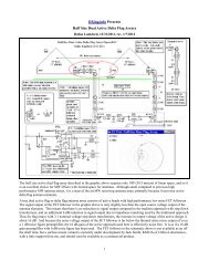
Attachment 1Below are depictions of the inductive coupling of receiver and passive loop in facing and adjacent orientations:Facing OrientationAdjacent OrientationMutual inductance occurs when the magnetic flux lines intersect. When the two coils are properly tuned, energy is transferred tothe receiver’s tuning coil from the passive loop’s coil as the latter induces a voltage in the tuning coil.The CircuitThe equivalent circuit of a receiver in proximity to apassive loop is shown at right. The two coils, wheninductively coupled, act as a transformer to transferenergy from the passive loop to the receiver. As aresult, the inductance and capacitance in the passiveloop is “seen” by the receiver’s antenna as a load whichis in parallel with the sense coil load.When in facing orientation, the dots on the transformerare on the same end, and in adjacent orientation theyare on opposite ends. When the two units aredecoupled, the mutual inductance factor (M) is zero,meaning that the circuit reduces to the simple RLCseries circuit in the bottom of the diagram; otherwise, Mappears to be on the order of 0.05 or less.Circuit EvaluationThe resultant circuit was evaluated using GenePreston’s AC.EXE program, varying the tuningcapacitance of the passive loop and the coupling of thetwo loops to simulate the various strategies. Below isan example of a loosely-coupled facing orientationsimulation, which resulted in a peak/notch spread of approximately 10 khz:* Linear plot at node 5, 100 lines of data, max voltage of 15000, ranging from 950 to 1050 khzLI 5 100 15000 9.5E5 10.5E5*Receiver tuning coil induced voltage at Node 1, max voltage is 1000 units of voltageVS 1 0 1000. 0*<strong>Passive</strong> loop coil induced voltage at Node 4VS 4 0 1000. 0*Receiver tuning coil 250 uHTF 1 2 250E-6 0*<strong>Passive</strong> loop coil 250 uH, mutual inductance factor = 0.02TF 3 4 250E-6 0.02*Receiver capacitor tuned to 1000 khzRC 2 5 2. 101.38E-12*<strong>Passive</strong> loop capacitor tuned to 1000 khzRC 3 0 2. 101.38E-12*Sense Coil Load – assume the sense coil ”sees” 800 ohms and transforms it to 50 ohms for the RF stageR 5 0 800. 0.8