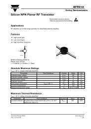
BF979 Silicon PNP Planar RF Transistor
BF979 Silicon PNP Planar RF Transistor
BF979 Silicon PNP Planar RF Transistor

You also want an ePaper? Increase the reach of your titles
YUMPU automatically turns print PDFs into web optimized ePapers that Google loves.
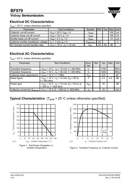
<strong>BF979</strong>Vishay SemiconductorsElectrical DC CharacteristicsT amb = 25 C, unless otherwise specifiedParameter Test Conditions Symbol Min Typ Max UnitCollector cut-off current –V CE = 20 V, V BE = 0 –I CES 100 ACollector-base cut-off current –V CB = 15 V, I E = 0 –I CBO 100 nAEmitter-base cut-off current –V EB = 3 V, I C = 0 –I EBO 10 ACollector-emitter breakdown voltage –I C = 1 mA, I B = 0 –V (BR)CEO 20 VDC forward current transfer ratio –V CE = 10 V, –I C = 10 mA h FE 20 50 90Electrical AC CharacteristicsT amb = 25 C, unless otherwise specifiedParameter Test Conditions SymbolMin Typ Max UnitTransition frequency –V CE = 10 V, –I C = 10 mA, f = 300 MHz f T 1750 MHzTransition frequency –V CE = 10 V, –I C = 30 mA, f = 300 MHz f T 1300 MHzCollector-base capacitance –V CB = 10 V, f = 1 MHz C cb 0.6 pFNoise figure –V CE = 10 V, –I C = 10 mA, Z S = 50 , F 3.4 4.2 dBf = 800 MHzPower gain–V CE = 10 V, –I C = 10 mA, Z S = 50 , Z L G pb 16 dB= 500 f = 800 MHzCollector current for G pbmax –V CE = 10 V, Z L = 500 f = 800 MHz –I C 10 mATypical Characteristics (T amb = 25 C unless otherwise specified)P tot – Total Power Dissipation ( mW )128454003503002502001501005000 20 40 60 80 100 120 140 160T amb – Ambient Temperature ( °C )Figure 1. Total Power Dissipation vs.Ambient Temperaturef – Transition Frequency ( MHz )T128482100180015001200900600300–V CB =10Vf=300MHz00 5 10 15 20 25 30 35–I C – Collector Current ( mA )Figure 2. Transition Frequency vs. Collector Currentwww.vishay.com2 (4)Document Number 85006Rev. 3, 20-Jan-99