User manual linear actuators and electronics - Linak
User manual linear actuators and electronics - Linak
User manual linear actuators and electronics - Linak

You also want an ePaper? Increase the reach of your titles
YUMPU automatically turns print PDFs into web optimized ePapers that Google loves.
USER MANUAL<br />
LINEAR ACTUATORS<br />
AND ELECTRONICS<br />
To learn more about LINAK, please visit:<br />
www.linak.com<br />
Page 1 of 80
Page 2 of 80
contents<br />
Preface . . . . . . . . . . . . . . . . . . . . . . . . . . . . . . . . . . . . . . . . . . . . . . . . . . . . . . . . . . . . . . . . . . . . . 4<br />
Valid for . . . . . . . . . . . . . . . . . . . . . . . . . . . . . . . . . . . . . . . . . . . . . . . . . . . . . . . . . . . . . . . . . . . . 5<br />
important information . . . . . . . . . . . . . . . . . . . . . . . . . . . . . . . . . . . . . . . . . . . . . . . . . . . . . . . . 6<br />
Safety instructions . . . . . . . . . . . . . . . . . . . . . . . . . . . . . . . . . . . . . . . . . . . . . . . . . . . . . . . . . . . . 6<br />
manufacturer’s declaration . . . . . . . . . . . . . . . . . . . . . . . . . . . . . . . . . . . . . . . . . . . . . . . . . . . . . 9<br />
1. System description . . . . . . . . . . . . . . . . . . . . . . . . . . . . . . . . . . . . . . . . . . . . . . . . . . . . . . . . . 10<br />
Fundamental actuator construction . . . . . . . . . . . . . . . . . . . . . . . . . . . . . . . . . . . . . . . . . . . . . . 11<br />
Warranty <strong>and</strong> service life . . . . . . . . . . . . . . . . . . . . . . . . . . . . . . . . . . . . . . . . . . . . . . . . . . . . . . 11<br />
IP Protection degree . . . . . . . . . . . . . . . . . . . . . . . . . . . . . . . . . . . . . . . . . . . . . . . . . . . . . . . . . 11<br />
LINAK washing procedure for IPX6 Washable products . . . . . . . . . . . . . . . . . . . . . . . . . . . . . . . 13<br />
Cable Wash . . . . . . . . . . . . . . . . . . . . . . . . . . . . . . . . . . . . . . . . . . . . . . . . . . . . . . . . . . . . . . . . 14<br />
Maintenance . . . . . . . . . . . . . . . . . . . . . . . . . . . . . . . . . . . . . . . . . . . . . . . . . . . . . . . . . . . . . . . 14<br />
Environmental conditions . . . . . . . . . . . . . . . . . . . . . . . . . . . . . . . . . . . . . . . . . . . . . . . . . . . . . . 14<br />
Insulation class . . . . . . . . . . . . . . . . . . . . . . . . . . . . . . . . . . . . . . . . . . . . . . . . . . . . . . . . . . . . . 15<br />
Key to symbols . . . . . . . . . . . . . . . . . . . . . . . . . . . . . . . . . . . . . . . . . . . . . . . . . . . . . . . . . . . . . 15<br />
Mounting . . . . . . . . . . . . . . . . . . . . . . . . . . . . . . . . . . . . . . . . . . . . . . . . . . . . . . . . . . . . . . . . . 16<br />
Connecting the system . . . . . . . . . . . . . . . . . . . . . . . . . . . . . . . . . . . . . . . . . . . . . . . . . . . . . . . 17<br />
JUMBO system (special information) . . . . . . . . . . . . . . . . . . . . . . . . . . . . . . . . . . . . . . . . . . . . . 18<br />
2. information on start-up, de-installation <strong>and</strong> operation . . . . . . . . . . . . . . . . . . . . . . . . . . . . 20<br />
Troubleshooting Actuators/Lifting columns . . . . . . . . . . . . . . . . . . . . . . . . . . . . . . . . . . . . . . . . 21<br />
Troubleshooting Electronics . . . . . . . . . . . . . . . . . . . . . . . . . . . . . . . . . . . . . . . . . . . . . . . . . . . . 21<br />
3. information on specific <strong>actuators</strong> . . . . . . . . . . . . . . . . . . . . . . . . . . . . . . . . . . . . . . . . . . . . . 22<br />
4. information on specific columns . . . . . . . . . . . . . . . . . . . . . . . . . . . . . . . . . . . . . . . . . . . . . . 39<br />
5. information on specific controls boxes . . . . . . . . . . . . . . . . . . . . . . . . . . . . . . . . . . . . . . . . . 47<br />
6. information on specific controls . . . . . . . . . . . . . . . . . . . . . . . . . . . . . . . . . . . . . . . . . . . . . . . 53<br />
7. information on specific JUmBo . . . . . . . . . . . . . . . . . . . . . . . . . . . . . . . . . . . . . . . . . . . . . . . 59<br />
8. information on specific accessories . . . . . . . . . . . . . . . . . . . . . . . . . . . . . . . . . . . . . . . . . . . . 64<br />
9. Repair <strong>and</strong> disposal . . . . . . . . . . . . . . . . . . . . . . . . . . . . . . . . . . . . . . . . . . . . . . . . . . . . . . . . . 67<br />
main groups of disposal . . . . . . . . . . . . . . . . . . . . . . . . . . . . . . . . . . . . . . . . . . . . . . . . . . . . . . . 68<br />
Practical information . . . . . . . . . . . . . . . . . . . . . . . . . . . . . . . . . . . . . . . . . . . . . . . . . . . . . . . . . . 70<br />
Drawings . . . . . . . . . . . . . . . . . . . . . . . . . . . . . . . . . . . . . . . . . . . . . . . . . . . . . . . . . . . . . . . . . . . 72<br />
addresses . . . . . . . . . . . . . . . . . . . . . . . . . . . . . . . . . . . . . . . . . . . . . . . . . . . . . . . . . . . . . . . . . . . 80<br />
Page 3 of 80
Preface<br />
Dear <strong>User</strong>,<br />
We are delighted that you have chosen a product from LINAK ® .<br />
LINAK systems are high-tech products based on many years of experience in the manufacture <strong>and</strong> development of <strong>actuators</strong>,<br />
electric control boxes, controls <strong>and</strong> chargers .<br />
This <strong>User</strong> Manual will tell you how to install, use <strong>and</strong> maintain your LINAK <strong>electronics</strong> . We are sure that your LINAK system will<br />
give you many years of problem-free operation .<br />
Before our products leave the factory they undergo full function <strong>and</strong> quality testing . Should you nevertheless experience<br />
problems with your systems, you are always welcome to contact your local dealer .<br />
LINAK subsidiaries <strong>and</strong> some distributors situated all over the world have authorised service centres, which are always ready to<br />
help you .<br />
LINAK provides a warranty on all its products .<br />
This warranty, however, is subject to correct use in accordance with the specifications, maintenance being done correctly <strong>and</strong><br />
any repairs being carried out at a service centre, which is authorised to repair LINAK products .<br />
Changes in installation <strong>and</strong> use of LINAK systems can affect their operation <strong>and</strong> durability . The products are not to be opened<br />
by unauthorised personnel .<br />
The <strong>User</strong> Manual has been written on the basis of our present technical knowledge . We are constantly working on updating<br />
the information <strong>and</strong> we therefore reserve the right to carry out technical modifications .<br />
linak a/S<br />
Page 4 of 80
Valid for:<br />
This <strong>User</strong> Manual is valid for the following products:<br />
(See the first 3 - 5 characters on the label)<br />
Actuators: LA12, LA22, LA23, LA27, LA28, LA29, LA30, LA31, LA32, LA34, LA43, LA43 IC, LA44, LA44 IC<br />
Columns: BB3, BL1, BL4, LC2, LP2, LP3<br />
Control boxes: CB6, CB6S, CB7, CB8-A, CB8-T, CB9, CB12, CB14, CB16, CB20, CBR1<br />
Controls: ACC, ACK, ACL, ACM, ACP, ACO, DPH, FPP, FS, FS2, HB20, HB40, HB50, HB60, HB70, HB80,<br />
HL70, HL80, IRO, LS, LSD<br />
JUMBO systems: BAJ1, BAJ2, CBJ1/2, CBJ-Care, CBJ-Home, COBO20, CH01, CHJ2, MBJ1/2/3<br />
Accessories: BA18, CS16, DJB, MJB, SLS, SMPS30<br />
Page 5 of 80
important information<br />
Description of the various signs used in this <strong>manual</strong>.<br />
warning!<br />
Failure to comply with these instructions may result in accidents involving serious personal injury .<br />
Failing to follow these instructions can result in the product being damaged or destroyed .<br />
Safety instructions<br />
Please read the following safety information carefully .<br />
It is important for everyone who is to connect, install or use the systems to have the necessary information <strong>and</strong> access to this <strong>User</strong><br />
Manual .<br />
Please be advised that LINAK has taken precautions to ensure the safety of the actuator system . It is the responsibility of the<br />
manufacturer/OEM to get the overall approval for the complete application .<br />
LINAK recommends that the <strong>actuators</strong> should be used in push applications, rather than pull applications .<br />
If the actuator is used for push in an application where personal injury can occur (e .g . patient hoists), a special safety nut must be used .<br />
In general the LA12 actuator is not to be used in push/pull situations .<br />
Relative or absoulte positioning for hte Plc connection<br />
Relative positioning - By means of a magnetic disc <strong>and</strong> a hall sensor in the PLC-actuator, it is possible to have encoder pulses with an<br />
accuracy down to 0 .5 mm per pulse . This signal can be connected directly to the PLC’s st<strong>and</strong>ard digital input .<br />
Absolute positioning - As an alternative the user can have a 0-10V analogue signal from a potentiometer integrated in the PLCactuator<br />
(max . stroke 100 mm) . This signal can be connected directly to an analogue PLC input .<br />
low energy consumption<br />
During recent years energy consumption has been more <strong>and</strong> more important to the end users of production equipment . Compared<br />
to pneumatic systems the energy consumption is considerably lower .<br />
Except for LA34 which can be used for both push or pull applications, if mounted with safety nuts in both directions .<br />
Persons who do not have the necessary experience or knowledge of the product/products must not use the product/products .<br />
Besides, persons with reduced physical or mental abilities must not use the product/products, unless they are under surveillance or<br />
they have been thoroughly instructed in the use of the apparatus by a person who is responsible for the safety of these persons .<br />
“Do not remain under the application during operation or operate the application when assembling/disassembling moving parts” .<br />
Moreover, children must be under surveillance to ensure that they do not play with the product .<br />
classification:<br />
The equipment is not suitable for use in the presence of a flammable anesthetic mixture with air or with oxygen or nitrous oxide .<br />
Electromagnetic compatibility<br />
LINAK Actuator Systems bear the CE marking as an attestation of compliance with the EMC Directive 2004/108/EC; the systems are<br />
designed to meet all requirements of applicable st<strong>and</strong>ards <strong>and</strong> have been tested to such requirements .<br />
It is unlikely that the user will encounter problems with the Actuator System because of inadequate electromagnetic compatibility .<br />
However, electromagnetic immunity is always relative <strong>and</strong> st<strong>and</strong>ards anticipate environments of usage . If the user notes unusual<br />
behaviour of the Actuator System, in particular if such behaviour is intermittent <strong>and</strong> associated with the st<strong>and</strong>ing right next to<br />
mobile phones, microwaves <strong>and</strong> radio broadcast masts, this could be an indication of electromagnetic interference . If such behaviour<br />
occurs, try to move the Actuator System further away from the interfering equipment .<br />
Electromagnetic emission is evaluated on a system level, with the actuator either connected to a LINAK Control Box <strong>and</strong> accessories<br />
or to some customer built electronic control circuitry . If used in other constellations <strong>and</strong> with external power supply, precautions may<br />
be taken to avoid conducted emission .<br />
warning!<br />
if the actuator or lifting column is used for pull in an application where personal injury can occur, the following<br />
is valid:<br />
It is the application manufacturer’s responsibility to incorporate a suitable safety arrangement, which will prevent<br />
personal injury from occurring, if the actuator should fail .<br />
Page 6 of 80
Residual risk<br />
Some of the products contains software based components . LINAK has done various possible efforts to assure that the<br />
software is free of errors <strong>and</strong> that the software has been developed according to the rules of IEC 60601-1-4 (software in<br />
Medical products) . That involves risk analysis which shows a small residual risk for unwanted/unintended mow of <strong>actuators</strong><br />
under specific conditions .<br />
According to the above rules it must be informed <strong>and</strong> if nescessary considered in the risk analysis of the final application<br />
- More details to residual risk can be provided by LINAK if nescessary .<br />
warning!<br />
Note that during construction of applications, in which the actuator is to be fitted, there must be no possibility of<br />
personal injury, for example the squeezing of fingers or arms .<br />
warning!<br />
The plastic parts in the system cannot tolerate cutting oil .<br />
warning!<br />
Assure free space for movement of application in both directions to avoid blockade<br />
warning!<br />
Uninstructed personell must not operate the application or the actuator<br />
warning!<br />
In the event of blockage by an obsticle when application is moving inwards, removing the obsticle will cause the load<br />
to drop until spindle hits the nut<br />
warning!<br />
Do not turn outer tube<br />
warning!<br />
Do not use chemicals, <strong>and</strong> inspect yearly for damage <strong>and</strong> wear .<br />
warnings!<br />
LINAK’s <strong>actuators</strong> <strong>and</strong> <strong>electronics</strong> are not constructed for use within the following fields:<br />
• Planes <strong>and</strong> other aircrafts<br />
• Explosive environments<br />
• Nuclear power generation<br />
warning!<br />
LINAK recommends that the <strong>actuators</strong> should be used in push applications, rather than pull applications .<br />
If the actuator is used for push in an application where personal injury can occur (e .g . patient hoists), a special safety<br />
nut must be used . Except for the LA34 which can be used for both push or pull applications, if mounted with safety<br />
nuts in both directions .<br />
warning!<br />
• If faults are observed, the products must be replaced .<br />
• Never spray directly on the products with a highpressure cleaner .<br />
warning!<br />
A LINAK control box, actuator <strong>and</strong> accessory component must, in the final application, be placed where it is not imposed<br />
to any impact . This is to prevent damage by accidentally being struck by an object in the h<strong>and</strong> of a passer-by<br />
or by a broomstick or a mop h<strong>and</strong>le during cleaning the floor . On a medical bed e .g . this might be underneath the<br />
mattress support platform . If necessary to mitigate this risk, additional protection might be required .<br />
warning!<br />
Do not shorten the battery, other loads than self-discharge flatten the battery <strong>and</strong> cause formation of lead sulphate, which,<br />
if left in this state for too long, will irreversibly damage the battery . Avoid bad impact on individuals <strong>and</strong> environment .<br />
warning!<br />
Prevent foreign objects or persons from unintentionally activating a footswitch or a h<strong>and</strong> control at any time e .g . during<br />
normal use or maintenance .<br />
A h<strong>and</strong> control could be activated by squeezing e .g . between the mattress <strong>and</strong> the bed frame/rails or when it hangs<br />
on an application that is activated by moving another application into it or by moving the application into something<br />
else, e .g . a wall, furniture, another application etc .<br />
warning!<br />
H<strong>and</strong>le batteries carefully .<br />
LINAK battery packs may emit hydrogen gas . So do not bring fire or a heated object close to the battery pack, <strong>and</strong> never<br />
use the battery near a spark, fuses <strong>and</strong>/or equipment that emits sparks . Further, do not store the battery in a closed<br />
environment or incorporate it into a closed structure of an enclosure . Doing so can cause an explosion, fire, equipment<br />
damage <strong>and</strong> bodily injury .<br />
Page 7 of 80
Do not connect the positive terminal <strong>and</strong> the negative terminal of the LINAK battery packs with a wire or other metals .<br />
Short-circuiting the terminals of the battery can cause burn injuries, damage to the storage battery or trigger explosions .<br />
Never connect the LINAK battery packs directly to a power supply socket or an automobile’s cigarette lighter without<br />
using a charger as a medium . Connecting the battery directly can cause the battery to leak fluid, generate heat, explode,<br />
cause fires or bodily burns <strong>and</strong> injuries .<br />
LINAK battery packs contain dilute sulphuric acid, which is a toxic substance . If the battery’s internal fluid leaks out <strong>and</strong><br />
gets onto your skin or clothing, make sure it is washed off with clean water . Additionally, if the fluid gets in your eyes,<br />
wash them with clean water immediately, <strong>and</strong> see a doctor . When dilute sulphuric acid gets in your eyes, it can cause a<br />
loss of eyesight <strong>and</strong> when it gets on your skin, it can cause a burn on your skin .<br />
Do not use or store LINAK battery packs where the surrounding temperature exceed 50°C, such as inside a hot automobile,<br />
in direct sunlight, or in front of a stove or a source of intense heat . Doing so can shorten battery life, lower its<br />
performance level, cause the battery to leak fluid, be damaged or deformed .<br />
For <strong>actuators</strong> without plugs, which are not connected to a LINAK control box, the mains supply or the actuator must<br />
always be equipped with an arrangement that switches off the actuator at the end-stop, for example, LS or LSD limit<br />
switch . If there is a risk of overloading the actuator, the mains supply must be equipped with a safety device against<br />
overloading (for example a CS16-PCB) . If these precautions are not observed, the actuator can be damaged .<br />
The LINAK products cannot tolerate the influence of strong solvents, basic or alkaline liquids .<br />
non-linak h<strong>and</strong>sets<br />
LINAK h<strong>and</strong>sets are designed specially for LINAK control boxes, <strong>and</strong> they are designed to be highly reliable <strong>and</strong> flexible<br />
. If the customer still wishes to use his own h<strong>and</strong>set, it is important to contact a LINAK sales person to find out the<br />
requirements with regard to the switches in the h<strong>and</strong>set . Poor switches can destroy the control box .<br />
The duty cycle printed on the label of the control box must always be noted . If this is exceeded, there is a risk of the<br />
control box being overheated <strong>and</strong> damaged . Unless otherwise specified on the label, the duty cycle is max . 10% :<br />
max . 2 min . in use followed by 18 min . not in use . Exceeding the duty cycle will result in a dramatic reduction of<br />
the product .<br />
Page 8 of 80
Page 9 of 80
1. System description:<br />
Usage/type of applications:<br />
LINAK <strong>actuators</strong>, lifting columns <strong>and</strong> <strong>electronics</strong> have been developed for use in all places where a <strong>linear</strong> movement is required .<br />
linak’s products can, for example, be used for:<br />
• Adjustment of beds<br />
• Adjustment of furniture<br />
• Adjustment of table heights <strong>and</strong> angles<br />
• Patient hoists within the care <strong>and</strong> hospital sector<br />
• Adjustment of industrial processing machines<br />
• Adjustment of agricultural machines<br />
• Adjustment of ventilation systems<br />
• Adjustment of dentist chairs/gynaecological chairs<br />
• Etc .<br />
The principles of a linak system are as follows:<br />
LINAK h<strong>and</strong>set LINAK <strong>actuators</strong> or lifting columns<br />
LINAK<br />
control box<br />
attention should be paid to the following:<br />
• Control boxes must only be connected to the mains voltage specified on the label . All DIN, jack, or minifit plugs from the<br />
CB6S/CB12/CB14/CB16/CB20 IPX6 Washable should be locked by using a LINAK locking mechanism .<br />
• The control box must be connected in such a way that the cables are not trapped, exposed to tension or sharp objects<br />
when the application is moved in different directions .<br />
• All Control boxes with mains supply should be connected to the mains before they are able to work.<br />
Prior to first use of LINAK batteries, please make sure that they are being charged 24 hours in order to reach proper function <strong>and</strong><br />
prolong the lifetime of the batteries .<br />
If the customer uses a non-LINAK battery, it is important to check that the current is not reversed (plus <strong>and</strong> minus swapped over)<br />
This applies to both control boxes, which always run off battery <strong>and</strong> control boxes with battery backup . Contact your nearest<br />
LINAK dealer for specification of type, size etc .<br />
The control current in the h<strong>and</strong>set cable must not exceed 100 mA .<br />
The control box is the heart of the system <strong>and</strong> connects the various outlying units (<strong>actuators</strong>, lifting columns, h<strong>and</strong>sets <strong>and</strong> attendent<br />
controls) . Control boxes differ widely in complexity . The simplest are only able to convert control signals from the h<strong>and</strong>set<br />
into operating voltage for the actuator . The most advanced are microprocessor controlled <strong>and</strong> have advanced functions such as,<br />
parallel running of several <strong>actuators</strong> <strong>and</strong> other complex correlations . Most LINAK control boxes provide an Electronic Overload<br />
Protection (EOP), designed to protect the actuator (excl . LA12, LA29, LA31, LA34), against overload by disconnecting the current<br />
when the actuator is fully extended or retracted . If an LA12, LA29, LA31, LA34 actuator is used, the built-in limit swit ches stop<br />
the actuator when fully extended or retracted, <strong>and</strong> the control box only disconnects when the maximum current is exceeded .<br />
When using a CB6S control box it is important to note that is does not have electronic overload protection .<br />
The actuator is the unit, which converts the operating voltage from the control box into a <strong>linear</strong> movement .<br />
The principle of the LINAK actuator’s mode of operation is that a low voltage DC motor (5), via a gear system (12), rotates a<br />
threaded spindle, onto which a nut is fitted . As this nut cannot rotate, since the piston rod (2) is restrained, the piston rod will<br />
move forwards or backwards, when the threaded spindle rotates .<br />
On the basis of motor type, gearing, <strong>and</strong> the threaded spindle’s pitch, the actuator’s thrust <strong>and</strong> speed are determined .<br />
The h<strong>and</strong>set is the unit to be used when you want the LINAK ® system to perform a movement . It determines whether the<br />
control box will make the actuator move in or out . There are many variants of LINAK h<strong>and</strong>sets .<br />
The attendant control (ACC, ACK, ACL, ACM, ACP, ACO) is an accessory used when nursing staff want to restrict the patients<br />
adjustment options of a bed . It is often used in conjunction with a h<strong>and</strong>set <strong>and</strong> disables selected functions on the h<strong>and</strong>set . It can<br />
also have control functions with the same function as those on the h<strong>and</strong>set .<br />
For safety reasons, open function activation of ACP <strong>and</strong> ACO (ACC, ACK) requires activation of two buttons .In case of a failure causing<br />
no movement, the application manufacturer must use other means to assure movement, e .g . quick release function .<br />
Page 10 of 80
Fundamental actuator construction<br />
9 10 8 7 6 5 4 3 2 1<br />
13<br />
1 . Piston rod eye<br />
2 . Piston rod<br />
3 . Location of mechanical splines<br />
4 . Location of brake<br />
11 12<br />
5 . Motor<br />
6 . Motor with optical switch<br />
7 . Motor with potentiometer<br />
8 . Motor with reed-switch<br />
9 . Back fixture<br />
Page 11 of 80<br />
10 . Back fixture with electrical splines<br />
11 . Quick release mechanism<br />
12 . Transmission between motor <strong>and</strong> spindle<br />
13 . Cable for connection to 12/24/36V DC by<br />
means of plug via control box<br />
warranty <strong>and</strong> service life<br />
The LINAK ® warranty covers manufacturing defects in the products, starting from the date of manufacture . There is 36 months’<br />
warranty on the HOMELINE ® products, 18 months’ for MEDLINE ® <strong>and</strong> CARELINE ® products, <strong>and</strong> 12 months’ for the TECHLINE ®<br />
products . The warranty is limited to the value of the LINAK product .<br />
LINAK’s guarantee is only valid so far as the products have been used <strong>and</strong> maintained correctly <strong>and</strong> has not been tampered with .<br />
Furthermore, the products must not be exposed to violent treatment . In the event of this, the warranty will be ineffective / invalid .<br />
LINAK’s warranty is only valid if the system is unopened <strong>and</strong> has been used correctly .<br />
All LINAK products are designed to have an optimum service life as a matter of course, but the expected service life in a specific<br />
application is very dependent on how the products are used .<br />
iP Protection degree:<br />
The products can be cleaned as follows according to their IP protection, which is stated on the product label .<br />
The IP code specifies the degrees of protection provided by the enclosures . For most products only the protection against ingress of<br />
water (second characteristic numeral) is specified, ingress of solid foreign objects or dust (first characteristic numeral) is not specified<br />
<strong>and</strong> therefore replaced by the letter X in the code . For some special industrial products both the first <strong>and</strong> second characteristic<br />
numerals are specified . This is a dem<strong>and</strong> from the marked <strong>and</strong> will only be specified if tested <strong>and</strong> approved .<br />
iP protection cleaning instructions<br />
IPX0 Clean with a damp cloth<br />
IPX1 Clean with a damp cloth<br />
IPX2 Clean with a damp cloth<br />
IPX3 Clean with a damp cloth<br />
IPX4 Clean with a damp cloth<br />
IPX5 Wash with a brush <strong>and</strong> water, but not water under pressure<br />
IPX6 Wash with a brush <strong>and</strong> water . The water can be under pressure, but the system<br />
must not be hosed down directly with a highpressure cleaner . Max . 20 o C<br />
IPX6 Washable* Clean by the use of wash tunnels<br />
IPX6 Washable according to IEC 60601-2-52 Clean by the use of wash tunnels according to IEC 60601-2-52
* IPX6 Washable products can be washed in wash tunnels according to the following guidelines :<br />
• The distance between the nozzle <strong>and</strong> the electrical parts must be at least 300 mm .<br />
• The h<strong>and</strong>set <strong>and</strong> motor plug must be pushed right in .<br />
• The water temperature must not exceed 65°C in max . 3 minutes<br />
• Cooling with cold water is not permitted .<br />
To avoid degreasing of the piston rod, the actuator should be retracted to minimum stroke before washing .<br />
warning!<br />
The systems must not be sprayed directly with a highpressure cleaner .<br />
warning!<br />
Interconnecting cables must remain plugged in during cleaning to prevent the ingress of water .<br />
warning!<br />
Cleaning with a steam cleaner is not permitted .<br />
Page 12 of 80
linak washing procedure for iPX6 washable products:<br />
Reference: The LINAK washing procedure is defined to duplicate the washing process of a hospital using a wash tunnel .<br />
This washing process has been chosen, as it sets a high st<strong>and</strong>ard regarding the sealing effectiveness of the products .<br />
chemicals: Use the Ecolab product Sekumatic FRE or a similar product with corresponding properties as detergent .<br />
Use the Ecolab product Sekumatic FKN or a similar product with corresponding properties as softener .<br />
Design: The LINAK washing machine is built with a large washing chamber containing more shelves, onto which the test<br />
products can be placed . Each shelf is surrounded by sprayjet rotor, they spray the test products from above <strong>and</strong><br />
below, so that all surfaces of the test products are sprayed upon .<br />
For more details see the picture below:<br />
Data for the LINAK development department’s test-washing machine .<br />
water volume: Each of the sprays supplies approx . 6 litres of water pr . minute, the equivalent of the test products on each of the<br />
shelves being sprayed with a totalt of approx . 75 l/min . Both during the washing process <strong>and</strong> during the rinsing<br />
process .<br />
Upper sprayjet rotor<br />
(sprays downwards)<br />
Middle sprayjet rotor<br />
(sprays both up <strong>and</strong> downwards)<br />
Lower sprayjet rotor<br />
(sprays upwards)<br />
Spray pressure: Both during the washing process <strong>and</strong> the rinsing process the washing machine operates with a spray pressure of<br />
0,4 bar . (overpressure)<br />
Temperature: The water temperature in both washing <strong>and</strong> rinsing is constant at 65°C . During the first 2 minutes the products<br />
are washed with 65° warm water <strong>and</strong> are here warmed up . After a few seconds the products are rinsed with 65°<br />
warm water for one minute <strong>and</strong> then cooled down in the ambient air temperature for about 15 minutes . A total<br />
cycle lasts for about 20 minutes . The diagram below is a graphic illustration of the process .<br />
If LINAK products with the IP protection class IP66 Washable go through a washing process which differs considerably<br />
from the above, there will be no guarantee for either the function or the life of the product .<br />
• Actuators are tested in the closed (run inwards) position.<br />
• CB’s are tested with plugs fitted.<br />
• The washing cycle is repeated 200 times during each test.<br />
comparison between temperature profile for linak <strong>and</strong> reference washing process from a hospital with a washing<br />
tunnel.<br />
Page 13 of 80
cable wash<br />
Before the washing procedure starts!<br />
In order to maintain the flexibility of the cables, it is important that the cable is placed in such a way that the cable’s own weight<br />
does not strain the coil during the washing process .<br />
This can be done by placing the cable ON the bed or another form of support for the cable .<br />
Please see the examples in the below pictures<br />
maintenance<br />
Valid for all linak products<br />
• The LINAK products must be cleaned at regular intervals to remove dust <strong>and</strong> dirt <strong>and</strong> inspected for mechanical damage, wear<br />
<strong>and</strong> breaks, - worn out parts must be replaced .<br />
• The LINAK products are closed units <strong>and</strong> require no internal maintenance .<br />
• Only type IPX6 is waterproof <strong>and</strong> type IPX6 Washable tolerates being washed in tunnels .<br />
• The LINAK products must be IPX6 Washable when cleaning in wash tunnels . Make sure that the plugs are correctly fitted<br />
with O-rings before washing .<br />
• o-rings: When individual parts are replaced in a LINAK IPX6 or IPX6 Washable system, the O-rings on all parts, must be<br />
replaced at the same time . On control boxes with a replaceable mains fuse, the O-ring in the fuse cover must be replaced every<br />
time the cover has been removed . The O-rings must be greased in water free vaseline when replacing them . Make sure that<br />
the counterpart - the socket - is clean <strong>and</strong> undamaged .<br />
Valid for all linak <strong>actuators</strong> <strong>and</strong> lifting columns<br />
• Actuators/lifting columns must be inspected at attachment points, wires, piston rod, cabinet, <strong>and</strong> plugs, as well as checking<br />
that the actuator/lifting columns function correctly .<br />
• To ensure that the pregreased inner tube remain lubricated the actuator must only be washed down when the piston rod is<br />
fully retracted .<br />
Valid for all linak control boxes <strong>and</strong> h<strong>and</strong>sets<br />
• Electronics must be inspected at attachment points, wires, cabinet, <strong>and</strong> plugs .<br />
• Inspect the connections, cables, cabinet, <strong>and</strong> plugs, <strong>and</strong> check for correct functioning (does not apply to battery versions) .<br />
• With the exception of the CS16 the control box is sealed <strong>and</strong> maintenance free .<br />
• Inspect at regular intervals that the ventilation aperture on the external battery is positioned correctly <strong>and</strong> is intact throughout<br />
its length, approx . 20 mm ., see figure 1 .<br />
Environmental conditions:<br />
Storage <strong>and</strong> transport<br />
Operating :<br />
Temperature<br />
Relative humidity<br />
Atmospheric pressure<br />
Storage :<br />
Temperature<br />
Relative humidity<br />
Atmospheric pressure<br />
Transport :<br />
If the actuator is assembled in the application <strong>and</strong> is exposed to push or pull during transportation, the<br />
actuator can be damaged .<br />
Do not drop an actuator or otherwise damage the housing during disassembly or transportation .<br />
We do not recommend using an actuator which has been damaged .<br />
Valid where nothing otherwise is stated under the specific products in a later section.<br />
Page 14 of 80<br />
5°C to 40°C<br />
20% to 90% @ 30°C – not condensing<br />
700 to 1060 hPa<br />
-10°C to +50°C<br />
20% to 90% @ 30°C – not condensing<br />
700 to 1060 hPa
insulation class:<br />
LINAK control boxes are available in insulation class 1 <strong>and</strong> insulation class 2 .<br />
Class 1 means with earth connection<br />
Class 2 means without earth connection<br />
When measuring the resistance in the earth connection in LINAK Control Boxes (class 1), it is recommended to use equipment,<br />
delivering a test current of no less than 5A . The resulting voltage will correspond to the resistance in the earth connection . Test currents<br />
below 5A, would yield no exact measurements .<br />
key to symbols<br />
The following symbols are used on the label on the LINAK products .<br />
Australian approval mark<br />
Recognised - Component Mark<br />
Canadian<br />
Recognised - Component Mark<br />
Recognised<br />
Component Mark for Canada <strong>and</strong> the United States<br />
TÜV Rheinl<strong>and</strong><br />
TÜV Rheinl<strong>and</strong> - LGA tested<br />
ETL<br />
C-ETL<br />
UL Listing Mark<br />
C-UL Listing Mark<br />
C-UL US Listing Mark<br />
UL Listing Mark<br />
UL file number<br />
UL file number<br />
PSE-Mark<br />
Product with a thermofuse<br />
For indoor use (House) .<br />
Safety isolating transformer .<br />
Electronics scrap<br />
Recycle<br />
Operating instructions<br />
iPXX<br />
Page 15 of 80<br />
Equipment Kl .2 (Double square)<br />
Patient part of type B (M<strong>and</strong>)<br />
Patient part of type BF<br />
Earth protective<br />
Earth<br />
CE Mark<br />
C-TICK<br />
China RoHS<br />
Protection against contact/foreign matter (first character)<br />
<strong>and</strong> water (second character) as per EN60529<br />
Alternating Current<br />
Direct current<br />
Attention, consult accompanying document<br />
Lock function<br />
Release function<br />
Charge indicator<br />
Safety switch/enable button<br />
Positioning of cell<br />
ZERO st<strong>and</strong>by power
mounting:<br />
actuator:<br />
Do not use any other screws for the mounting brackets than those recommended by LINAK . If longer screws are used they will come<br />
into contact with the inner parts of the actuator . This will result in an irregular operation or even damage the actuator .<br />
During mounting, the actuator must always be:<br />
• Fixed, to protect it against torque <strong>and</strong> bending . See Figure 2.<br />
• Fixed, so that it is restrained, but free to move on its mountings . See Figure 3.<br />
• Fixed in brackets, which can take up the torque reaction . See Figure 3.<br />
• Mounted at right angles, so that the right angle requirement is observed . See Figure 4.<br />
• Mounted with correct bolt dimension .<br />
• Mounted with bolts <strong>and</strong> nuts made of high quality steel grade (e .g . 10 .8) . No thread on bolt inside back fixture or piston rod eye .<br />
• Bolts <strong>and</strong> nuts must be protected from being able to fall out .<br />
• Inspect the actuator for damage before mounting . Damaged actuator must not be mounted . Watch e .g . for damaged packaging .<br />
• Do not use a too high tourque when mounting the bolts for back fixture or piston rod eye<br />
control boxes:<br />
• The mounting screws on the control box must be tightened with a maximum torque of 1 Nm<br />
• The mounting surface to which the control box is attached should have a surface evenness better than ± 0 .5 mm .<br />
• Systems must not be installed/deinstalled while in operation .<br />
• Control boxes with a wet alarm must be mounted as shown on figure 5 .<br />
• Nuts <strong>and</strong> bolts must be made of steel .<br />
• Nuts <strong>and</strong> bolts must be tightened securely .<br />
The correct bolt size for securing the CB8, CB12, CB14, CB16 <strong>and</strong> CB20, is Ø5 mm <strong>and</strong> the ACP box is M5 .<br />
cables:<br />
It is important to remove the transport plastic bag before using the cable .<br />
Cables need to be fixed to the application or to be placed in such a way that users cannot stumble <strong>and</strong> injure themselves<br />
.<br />
Page 16 of 80
connecting the system:<br />
Do not connect the mains cable until all <strong>actuators</strong> <strong>and</strong> h<strong>and</strong>sets have been connected to the control box .<br />
Start by connecting the h<strong>and</strong>set to the control box . The connection in the control box is marked with “HB” .<br />
Connect the different <strong>actuators</strong> to the different channels on the control box . Each channel is marked with a number (e .g . “1”,<br />
“2”, “3”…… .) .<br />
Check that all plugs are well connected <strong>and</strong> firm pushed into the connection plug . Due to the fact that LINAK control boxes are<br />
designed for a high IP degree a firm force can be required .<br />
connect the mains cable.<br />
The <strong>actuators</strong> can now be operated by pushing a button on the h<strong>and</strong>set . Use only one button at the time . If the control box is<br />
equipped with a special software an initializing process might be necessary . This process is described in the software specification .<br />
LINAK h<strong>and</strong>set LINAK actuator or lifting column<br />
LINAK<br />
control box<br />
attention should be paid to the following:<br />
• Control boxes must only be connected to the mains voltage specified on the label . All DIN, jack or minifit plugs from the<br />
CB6S/CB12/CB14/CB16/CB20 IPX6 Washable should be locked by using a LINAK locking mechanism .<br />
• The control box must be connected in such a way that the cables are not trapped, exposed to tension or sharp objects<br />
when the application is moved in different directions .<br />
• All Control boxes with mains supply should be connected to the mains before they are able to work.<br />
Prior to first use of LINAK batteries, please make sure that they are being charged 24 hours in order to reach proper function <strong>and</strong><br />
prolong the lifetime of the batteries .<br />
If the customer uses a non-LINAK battery, it is important to check that the current is not reversed (plus <strong>and</strong> minus swapped over)<br />
This applies to both control boxes, which always run off battery <strong>and</strong> control boxes with battery backup . Contact your nearest<br />
LINAK dealer for specification of type, size etc . The control current in the h<strong>and</strong>set cable must not exceed 100 mA .<br />
Any non-detachable power supply cord with mains plug is considered as the disconnecting device .<br />
Charging is only allowed in dry environment, <strong>and</strong> appliance inlet must be thoroughly dried before connecting to mains .<br />
All types of <strong>actuators</strong> may only be connected according to the label, where the voltages 12, 24, or 36 VDC are indicated .<br />
a) Actuators with jack plugs may only be connected to LINAK control boxes<br />
b) Actuators without plugs are connected as shown in Figures 6.1 - 6.12.<br />
For <strong>actuators</strong> operating without a control box, the mains supply of the actuator must be equipped with an arrangement, which<br />
switches off the actuator at end-stop (e .g . LS or LSD limit switch) . If there is a risk of overloading the actuator, the mains supply<br />
must be equipped with a safety device against overloading (e .g . a CS16 PCB) . If this requirement is not observed, the actuator<br />
may be damaged .<br />
Actuators with internal control PCBs’s are not first failure safe if used in a system combination without power request (power for<br />
actuator switched ON only when h<strong>and</strong>set key active) .<br />
Page 17 of 80
JUmBo Tm system (special information):<br />
The LINAK JUMBO system is specially developed for patient lifts, offering various combinations of <strong>actuators</strong> <strong>and</strong> control boxes .<br />
connecting the system:<br />
Mount the mounting bracket (MBJ) to the application . Mount control box <strong>and</strong> battery (<strong>and</strong> charger (CHJ2) if equipped) .<br />
If it is a JUMBO Home system mount the control box on the application (no mounting bracket is needed) . Only vertical mounting<br />
allowed (connectors fwacing downwards) .<br />
Connect the h<strong>and</strong>set to the control box . The connection in the control box is marked with “HB” .<br />
Connect the <strong>actuators</strong> to the control box . Each channel is marked with a number (e .g . “1”, “2”) . Channel “1” has always to be<br />
used for the High / Low (Lifting) function .<br />
The <strong>actuators</strong> can now be operated by pushing a button on the h<strong>and</strong>set . Use only one button at the time .<br />
Recommendations:<br />
It is recommended having other devices, e .g . a quick release, manuel lowering make the application move without power .<br />
And, after service, the application must be tested for correct functionality before putting it back into operation .<br />
Example of JUmBo patient lift system<br />
System components: Actuators, types LA28, LA32, LA34, LA44<br />
Control Box, types CBJ1/CBJ2, CBJC<br />
Batteries, types BAJ1, BAJ2<br />
H<strong>and</strong>sets, types HB5, HB7, HB8<br />
Battery Charger CH01<br />
Page 18 of 80<br />
1 H<strong>and</strong>set<br />
2 Battery<br />
3 Charger<br />
4 Control box<br />
5 Mains plug<br />
6 + 7 Actuators
configuration of the JUmBo System<br />
JUmBo Home System<br />
1 Battery<br />
1) 2)<br />
1<br />
2<br />
3<br />
4<br />
2 Emergency stop<br />
3 Control box<br />
4 LCD-display for battery<br />
condition<br />
1<br />
2<br />
3<br />
4<br />
1 Battery<br />
2 Charger<br />
3 Light indication for mains connection<br />
4 Light indication for charging<br />
Page 19 of 80<br />
3)<br />
1<br />
2<br />
3<br />
4<br />
5 6<br />
1 Battery<br />
2 Charger<br />
3 Control box<br />
4 Output for h<strong>and</strong><br />
5 + 6 Output actuator
2. information on start-up, de-installation <strong>and</strong> operation:<br />
Before installation, de-installation, or troubleshooting:<br />
• Stop the actuator/lifting column .<br />
• Switch off the power supply or pull out the mains plug <strong>and</strong> pull out the plug to the actuator/lifting column .<br />
• Relieve the actuator/lifting column of any loads, which may be released during the work .<br />
Prior to first use of LINAK batteries, please make sure that they are being charged 24 hours in order to reach proper function <strong>and</strong><br />
prolong the lifetime of the batteries .<br />
Before start-up:<br />
• Make sure that the system has been installed as instructed in the <strong>User</strong> Manual .<br />
• The individual parts (actuator/lifting column/h<strong>and</strong>sets etc .) must be connected before the control box is connected to the<br />
mains .<br />
• Make sure that the voltage of the mains to be connected to the product or the system is the one stated on the label .<br />
• Make sure that the actuator/lifting column is connected to a mains electricity supply/transformer with the correct voltage <strong>and</strong><br />
which is dimensioned <strong>and</strong> adapted for the actuator in question .<br />
• The equipment can be freely moved over the actuator/lifting column’s whole working area .<br />
• Check correct function after mounting .<br />
• The actuator/lifting column must not be loaded in excess of the values indicated in the specifications on the product label .<br />
• The duty cycle noted on the product label must always be noted . Otherwise there is a risk of damaging the products .<br />
Exceeding the duty cycle will result in a dramatic reduction of the life time of the system . Unless specified otherwise on the<br />
product label the duty cycle is max . 10% : Max . 2 minutes in use followed by 18 minutes not in use .<br />
• The actuator/lifting column system may only be used in an environment corresponding to the system’s IP-rating . LINAK<br />
products are marked with the actual IP-rating on the label .<br />
• If any individual parts are suspected to be damages, do not install the parts, but return them for inspection/service .<br />
During operation:<br />
• Listen for unusual sounds <strong>and</strong> watch out for uneven running . Stop the actuator/lifting column immediately if anything<br />
unusual is observed .<br />
• If the control box makes unusual noises or smells, switch off the mains voltage immediately <strong>and</strong> the external battery, if any .<br />
• Take care that the cables are not damaged .<br />
• Unplug the mains cable on mobile equipment before it is moved .<br />
Page 20 of 80
Troubleshooting <strong>actuators</strong>/lifting columns<br />
Symptom Possible cause action<br />
No motor sound or movement of - The actuator is not connnected to the - Connect the actuator to the<br />
piston rod control box control box<br />
- Blown fuse in the control box - Fuse must be changed<br />
- Cable damaged - Send actuator for repair<br />
Excessive electricity consumption - Send actuator for repair<br />
Motor runs but spindle does not move - Gear wheel or spindle damaged - Send actuator for repair<br />
Actuator cannot lift full load - Clutch is worn - Send actuator for repair<br />
- Motor is damaged<br />
Motor sound but no movement<br />
of piston rod<br />
- Send actuator for repair<br />
No signal from Reed or Hall switch - Send actuator for repair<br />
Motor runs <strong>and</strong> quick release does not<br />
function or is noisy<br />
- Declutching arm turns less than approx . 75° - Adjust cable<br />
Piston rod will only move inwards <strong>and</strong><br />
not outwards<br />
- Safety nut has operated - Send actuator for repair<br />
Motor runs too slowly or does not - Insufficient power supply - Increase power supply<br />
give full force - Voltage drop in cable - Thicker cable<br />
Troubleshooting Electronics<br />
Symptom Possible cause action<br />
Power indicator does not light up - Not connected to mains - Connect to mains<br />
- The fuse has blown - Replace fuse, if the system is prepared for<br />
external fuse replacement, or send the<br />
system for repair<br />
- Defective power cable - On control boxes with exchangeable power<br />
cable change the cable .<br />
- On control boxes with fixed cable send it<br />
for repair<br />
- Control box defective - Send control box for repair<br />
Power indicator lights up, but actuator - Actuator plug not pushed into - Push actuator plug into control box properly<br />
does not run control box properly<br />
Relays in control box are - Actuator defective - Replace actuator<br />
heard clicking - Control box defective<br />
- Replace the control box<br />
Power indicator lights up, but<br />
actuator does not run<br />
- Control box defective - Send control box for repair<br />
No relay noise is heard from<br />
control box<br />
Not valid for<br />
CB20/CB6S OBF/CB16 OBF<br />
- H<strong>and</strong>set defective - Send h<strong>and</strong>set for repair<br />
Control box completely dead on battery<br />
<strong>and</strong> no relay clicking is heard<br />
- Battery completely flat - Charge battery<br />
- Battery defective - Replace battery<br />
Actuator does not run on battery, - Actuator plug not properly - Push actuator plug properly into control box<br />
but relay clicking is heard pushed into control box<br />
- Actuator defective - Replace actuator<br />
- Control box defective - Replace control box<br />
Control box okay apart from one - H<strong>and</strong>set defective - Send h<strong>and</strong>set for repair<br />
direction on one channel - Control box defective - Send control box for repair<br />
Page 21 of 80
3. information on specific <strong>actuators</strong> :<br />
1. la12 (TEcHlinE ® )<br />
Thanks to the small size <strong>and</strong> outst<strong>and</strong>ing performance, the LA12 actuator<br />
provides a practical <strong>and</strong> cost-effective alternative to traditional pneumatic<br />
systems <strong>and</strong> gear motors .<br />
The LA12 is ideal for automating industrial <strong>and</strong> agricultural machines, feeding,<br />
ventilation systems troughs <strong>and</strong> many other applications requiring short<br />
<strong>linear</strong> movement .<br />
installation instructions<br />
The <strong>actuators</strong> model LA12 must be installed in a fixed position .<br />
Reed-switch:<br />
Reed-switch gives a number of pulses for each rotation of the motor . These<br />
pulses are used to calculate the piston rod’s position as well as to control<br />
several <strong>actuators</strong> running in parallel .<br />
Your nearest LINAK dealer can inform the number of pulses per stroke length .<br />
Regarding Reed-switch connection, see Figure 6.4 (LA12R)<br />
If the LA12 actuator is mounted in an application where a mechanical stop prevents the installed end-stop switches in LA12 from<br />
being activated, the LA12 actuator must be equipped either with an electrical safety device, a timer or an electronic limit switch .<br />
Therefore, please contact your nearest LINAK dealer for technical data .<br />
Built-in end-stop circuit<br />
The end-stop switch is part of the actuator construction . Each time the actuator reaches end-stop position the switch is activated<br />
<strong>and</strong> the current is cut off .<br />
2. la22 (mEDlinE ® caRElinE ® TEcHlinE ® )<br />
3. la23 (mEDlinE ® caRElinE ® TEcHlinE ® )<br />
The LA22 is an in-line actuator specially designed with a small overall dimension<br />
for easy use in industrial, agricultural, <strong>and</strong> rehabilitation products .<br />
Thanks to its small outer dimensions <strong>and</strong> <strong>linear</strong> design, the LA22 is well suited<br />
for applications where installation space is limited, such as on wheelchairs .<br />
The LA23 is a small <strong>and</strong> strong push/pull actuator (up to 2500N) . LA23 can<br />
be used in various applications where size is important . The actuator does<br />
have build in electrical limit switches <strong>and</strong> guided nut .<br />
Usage:<br />
• Duty cycle: 10%, 2 minutes continuous use followed by 18 minutes not in<br />
use .<br />
• Usage temperature: -30°C to +55°C (according to ISO 7176-9)<br />
• Storage temperature: -45°C to +70°C (according to ISO 7176-9)<br />
• Compatibility: Is approved <strong>and</strong> tested to run with: CB20, CB16 <strong>and</strong> CB6S.<br />
Will be approved <strong>and</strong> tested to run with: CBJ1/2, CBJC, CBJH, <strong>and</strong> CB8<br />
(Approval pending) .<br />
• Approvals: Is approved according to DS/EN60601-1 <strong>and</strong> UL60601-1<br />
• Cycles: 3 mm pitch (2500N) = 5000 cycles guaranteed<br />
Page 22 of 80
warnings!<br />
• Do not sideload the actuator.<br />
• Do only use the actuator within specified working limits.<br />
• Always use steel backfixture for LA23 2500N versions <strong>and</strong> for pull load.<br />
• The B <strong>and</strong> G 24V motors must only be used with their respective control box types.<br />
- Motor type A: 12V motor<br />
- Motor type B: 24V motor which must be used with JUMBO; CBJ1/2, CBJC <strong>and</strong> CBJH or generally in applications which are<br />
mainly driven with battery<br />
- Motor type G: 24V motor which must be used with OpenBus TM control boxes; CB20, CB16, CB6s .<br />
• If an actuator with stroke length below 50 mm is used, <strong>and</strong> the electrical end-stop switch fails, please be aware that the<br />
distance before reaching the mechanical end-stop will be prolonged . The extra distance will be 50 mm minus actual stroke length .<br />
I .e . If an actuator with 20 mm stroke length is used <strong>and</strong> the switch fails, it will travel an additional 30 mm before reaching the<br />
mechanical end-stop .<br />
• Instruction concerning the turning of the piston rod eye. When mounting <strong>and</strong> taking into use, it is not permitted to make<br />
excessive turns of the piston rod eye . In cases where the eye is not positioned correctly, it is permitted to first screw the eye down<br />
to its bottom position, at a maximum torque of 2 Nm (1), <strong>and</strong> thereafter a maximum half turn outwards again (2) .<br />
• If stroke is less than 50 mm <strong>and</strong> the outer limit switch fails it will be possible to drive the<br />
actuator up to stroke of 52 mm before the mechanical end stop take effect . Please make<br />
sure that the application can withst<strong>and</strong> this in a safe way .<br />
• When mounting the LA23 in the application ensure that the bolts can withst<strong>and</strong> the wear<br />
<strong>and</strong> that they are secured safely .<br />
• Do not place load on the actuator housing <strong>and</strong> do prevent impact, or blows or any other<br />
form of stress to the housing .<br />
• All LA23 PLC variants are not compliant for medical use.<br />
Recommendations:<br />
• Ensure that the cable lock is mounted correct.<br />
• Ensure that the duty cycle <strong>and</strong> the usage temperatures for LA23 <strong>actuators</strong> is respected<br />
• Ensure that the cable cannot be squeezed, pulled or subjected to any other stress.<br />
• If a cable lock has been removed it is recommended to check if it is has been damaged during removal. If so it is recommended<br />
to replace with a new one .<br />
• Before mounting a cable, ensure that the cable, cable plug or o-ring is not damaged. If damage is observed, the cable must be<br />
replaced with a new one .<br />
• The B <strong>and</strong> G 24V motors must only be used with their respective control box types.<br />
• Not acceptable: B motor with OpenBus control boxes!<br />
Reason: The actuator will be too strong, it will run too fast, be noisy <strong>and</strong> only have a short lifetime . The actuator will not live up<br />
to what we promise .<br />
• Not acceptable: G motor with 24V supply!<br />
Reason: The actuator will be too weak, this means it will only run slowly, not be able to lift as much in the cold <strong>and</strong> under low<br />
current conditions . The actuator will not live up to what we promise .<br />
The item numbers for ordering the Cable Lock are:<br />
• Item number: 0231007 (light grey) for one cable lock (1 piece).<br />
• Item number: 0231037 (black) for one cable lock (1 piece). Below you see an instruction in how to mount <strong>and</strong> remove the<br />
cable lock from LA23 .<br />
a) mount a cable lock:<br />
b) cable lock removal<br />
Step 1:<br />
Insert e.g. a<br />
screwdriver at<br />
a 45° angle as<br />
illustrated.<br />
Page 23 of 80<br />
Push down until the cable lockclicks into place.<br />
Step 2:<br />
Turn the screwdriver<br />
to release<br />
the cable lock.<br />
Note: When a cable lock has been removed, it is recommended to replace it with a new.<br />
Step 3:<br />
Now the cable<br />
lock can be<br />
removed by<br />
h<strong>and</strong>.
connection diagrams:<br />
Basic LA23<br />
LA23XXXXXX00XXXXX<br />
LA23 with potential free end stop<br />
LA23XXXXXX01XXXXX<br />
LA23 with st<strong>and</strong>ard dual hall<br />
LA23XXXXXX02XXXXX<br />
LA23 with dual hall PNP<br />
LA23XXXXXX03XXXXX<br />
LA23 with analog postion feedback<br />
(Hall potentiometer) <strong>and</strong> potential free endstop .<br />
Page 24 of 80<br />
LA23 with analog position feedback<br />
(Hall potentiometer) .<br />
LA23 with PWM position feedback<br />
(Hall potentiometer) <strong>and</strong> potential free endstop .<br />
LA23 with PWM position feedback<br />
(Hall potentiometer) .<br />
LA23 PLC with position feedback<br />
(Analog, PWM, Single Hall, None)<br />
note:<br />
For <strong>actuators</strong> connected to LINAK CB’s:<br />
If reversed driving is wanted this have to be done with special<br />
cables . Please concact LINAK if needed .<br />
For <strong>actuators</strong> with hall analog or PWM positioning feedback:<br />
Limit supply to 500 mA or 500 mA Fuse in case of wrong polarisation<br />
.
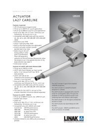
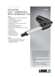
4. la27 (mEDlinE ® caRElinE ® HomElinE ® )<br />
The LA27 actuator is a powerful actuator designed for applications such as<br />
furniture <strong>and</strong> care beds .<br />
Built-in end-stop circuit (cS27)<br />
In the LA27/CS27 the actuator is switched off at the end position . There is no<br />
overload protection .<br />
• The LA27CS27 has no IP classification <strong>and</strong> is connected to a HB71 or HB72 .<br />
The power supply is the TR6 or TR7 .<br />
It is important that the supply voltage 24 VDC is connected correctly (see<br />
Figure 6.7) otherwise the CS-circuit may be destroyed .<br />
mechanical spline:<br />
The splines function so that the actuator can only push, not pull . During pull<br />
in the actuator, the inner tube is lifted off the thread bush, <strong>and</strong> the actuator<br />
can therefore never pull a load, only push .<br />
Functional test of mechanical splines:<br />
When the piston rod is at the innermost position, it must be possible to pull it out <strong>manual</strong>ly to its full travel length <strong>and</strong> to press it in<br />
again without much resistance <strong>and</strong> without using the motor . If this is not possible, contact your nearest LINAK dealer .<br />
Quick Release:<br />
The LA27 with QR is designed to be used as a part of the backrest function in a Care/Hospital bed . The QR function allows a patient<br />
to be lowered <strong>manual</strong>ly to a flat position very quickly (CPR) in case of an emergency .<br />
Functional test of QR:<br />
To test a LA27QR it is necesarry to have the actuator built into an application . The release cable has to be provided <strong>and</strong> mounted<br />
by the customer .<br />
The necesarry force on the cable requiered to operate the Quick Release is approx . 20 kg . The necesarry force on the actuator to<br />
operate the quick release is approx . 50 kg . Wenn operating the QR, it is recommended that the QR is activated all the way down .<br />
Usage:<br />
• Duty cycle: 2/18; 2 minutes continuous use followed by 18 minutes not in use<br />
• Duty cycle: Max 5% or 1 min . continuous use followed by 19 minutes not in use - with 8000N version .<br />
• Lifetime limited to only 3000 cycles according to EN1970 - with 8000N version<br />
• Ambient temperature: +5o to +40oC (the actuator must also be at this temp .)<br />
• LA27 is approved according to EN 60601-1 / UL60601-1<br />
NOTE: re. LA27 with 6.000N specification (274x3xxx1xxx0xZ; Z = A or B i.e with Bouverat worm axle*) for OpenBus: I.e. to use<br />
such combination a preceding test MUST be carried out .<br />
This combination reduces the self-lock ability because of lower friction from the Bouverat worm which has a rolled axle . The Bouverat<br />
worm is however needed because of the OpenBus output power.<br />
The alternative is a milled worm axle, but this may mean reduced lifetime of the worm .<br />
The problem related to an application:<br />
The self-lock ability may be reduced in cases where the load curve is 6 .000N in both minimum <strong>and</strong> maximum stroke length - see<br />
(A) . Further such load distribution may reduce the lifetime of actuator .<br />
A reduced load curve e .g . as in illustration (B) may also result in reduced self-lock, however it may have less impact on the lifetime<br />
of the actuator .<br />
Required test to ensure compatibility: (only needed for LA27 with 6.000N for OpenBus (274x3xxx1xxx0xZ; Z = A or B))<br />
The purpose is:<br />
• to observe the actual load curve distribution (comparison to above curves). If load curve results are better than the above you<br />
can proceed . If in doubt about evaluating the load curves please contact your LINAK A/S sales engineer .<br />
• to observe the self-lock ability in the actual application. In fact the application design may support the self-lock ability in such<br />
a way so that LA27 no longer sinks . Normally the actuator is not allowed to sink, however it is the customer who decides if it<br />
can be accepted (depends on the application type) .<br />
• a lifetime test MUST be carried out by the LINAK Subsidiary or be documented by the customer to ensure that mutual expectations<br />
are met .<br />
I .e . All LA27 with 6 .000 N load specification (all 4 mm spindle types) MUST be tested as described before they can be accepted for<br />
running production . However samples for test are available .<br />
Page 25 of 80
FOOTNOTE:<br />
* REMARK: Z as type ‘0’ does not use the Bouverat worm . However type ‘0’ is NOT compatible with the transformer used for<br />
OpenBus CB’s.<br />
warning!<br />
• If the actuator does not work as described above, the risk of injury due to squeezing can arise . The actuator must therefore<br />
immediately be sent for service at the nearest, authorised LINAK workshop .<br />
• The actuator must not be used in pull applications when the quick release is activated, as the risk of personal injury can arise .<br />
• Do only use the actuator within specified working limits .<br />
• Do not sideload the actuator .<br />
Recommendations:<br />
• LA27 is not meant to have CB6S OBL/OBF mounted on the actuator. The CB6S OBL/OBF must be mounted separately using a<br />
bracket .<br />
• LA27 must have a minimum installation dimension of 320 mm if control box CB6 is to be mounted on the actuator.<br />
• The cable for the LA27 is not part of the actuator therefore it must be ordered separately.<br />
• Piston rod eye: The distance from the centre of the eye, to the end of the actuator.<br />
• Change between push <strong>and</strong> pull not allowed<br />
• Inspect actuator once a year, for wear <strong>and</strong> jarring sound.<br />
• We recommend using a safety nut in medical applications<br />
• Do not expose <strong>actuators</strong> without all cables fitted to water/cleaning.<br />
• No thread on bolt inside back fixture.<br />
note:<br />
For CB6 the current will be cut off when the total current on all channels reaches approx . 5 .1 to 5 .4 Amp . This means that when<br />
two LA27´s running simultaneously are connected to a CB6 they will not be able to lift the max . load mentioned under technical<br />
specifications .<br />
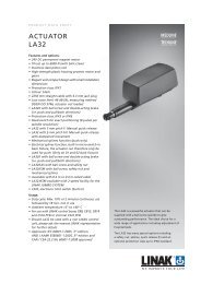
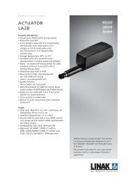
5. la28 (mEDlinE ® caRElinE ® TEcHlinE ® )<br />
The LA28 is primarily a system actuator . The actuator is very quiet <strong>and</strong> powerful<br />
designed for use in the furniture, rehabilitation, <strong>and</strong> hospital bed line of<br />
businesses .<br />
The actuator is also ideal for use in agricultural machinery <strong>and</strong> for a wide<br />
range of industrial applications .<br />
Reed-switch:<br />
Reed-switch gives a number of pulses for each rotation of the motor . These<br />
pulses are used to calculate the piston rod’s position as well as to control<br />
several <strong>actuators</strong> running in parallel .<br />
Your nearest LINAK dealer can inform the number of pulses per stroke length .<br />
Regarding Reed-switch connection, Figure 6.8 (LA28R)<br />
Built-in end-stop circuit (cS28/cS28S)<br />
In the LA28 actuator, with built-in CS28 A-, B- or C-PCB, the actuator is switched off at the end position or when overloaded .<br />
la28 actuator with:<br />
• The CS28 A is st<strong>and</strong>ard IPX1 <strong>and</strong> is connected to a HB41 h<strong>and</strong>set with a telephone plug .<br />
• The CS28 B is st<strong>and</strong>ard IPX5 <strong>and</strong> is connected to a HB41 h<strong>and</strong>set with a DIN plug . CS32 B is also available in IPX6 .<br />
• The CS28 C is st<strong>and</strong>ard IPX1 <strong>and</strong> is connected to an external contact or control . See figure 6.7.<br />
mechanical spline:<br />
The splines function so that the actuator can only push, not pull . During pull in the actuator, the inner tube is lifted off the thread<br />
bush, <strong>and</strong> the actuator can therefore never pull a load, only push .<br />
Functional test of mechanical splines:<br />
When the piston rod is at the innermost position, it must be possible to pull it out <strong>manual</strong>ly to its full travel length <strong>and</strong> to press it in<br />
again without much resistance <strong>and</strong> without using the motor . If this is not possible, contact your nearest LINAK dealer .<br />
warning!<br />
Do only use the actuator within specified working limits .<br />
Page 26 of 80
Usage:<br />
• Duty cycle: Max. 10 % or max. 2 min. continuous use followed by 18 min. not in use.<br />
• Ambient temperatures: +5° to +40°C<br />
Recommendations:<br />
• LINAK control boxes are designed so that they will short-circuit the motor terminals of the actuator(s), when the actuator(s) are<br />
not running . This solution gives the actuator(s) a higher self-locking ability . If the actuator(s) are not connected to a LINAK<br />
control box, the terminals of the motor must be short-circuited to enable self-locking of the actuator .<br />
• The maximum load in pull is 2000N.<br />
• Min. stroke length for the LA28 with splines is 80 mm<br />
• The current supply to LINAK <strong>actuators</strong> must be cut off in case of overload <strong>and</strong> when the <strong>actuators</strong> reach end position .<br />
• Ambient operating temperature is 22°C.<br />
• LA28 Compact cannot be used in pull applications, unless fitted with an aluminium back fixture.<br />
Further information:<br />
noise level:<br />
• LA28: dB(A) 45; measuring method DS/EN ISO 3746, actuator not loaded<br />
• LA28S: dB(A) 54; measuring method DS/EN ISO 3746, actuator not loaded<br />
material:<br />
• The piston rod eyes are “crimped” in place <strong>and</strong> cannot be unscrewed.<br />
6. la29 (HomElinE ® )<br />
“Crimped” piston rod eye Piston rod without eye (are not tested)<br />
Page 27 of 80<br />
Protective<br />
cap<br />
The LA29 actuator is a HOMELINE actuator, specially made for domestic<br />
applications like recliners .<br />
The actuator has a very short installation dimension as the distance between<br />
the two fixing points is small when the actuator is retracted <strong>and</strong> at<br />
the same time independent of the stroke length .<br />
Reed switch:<br />
The Reed switch gives a number of pulses for each rotation of the motor .<br />
These pulses are used to calculate the position as well as to control several<br />
<strong>actuators</strong> running in parallel .<br />
Your nearest LINAK dealer can inform the number of pulses per stroke<br />
length .<br />
Regarding Reed-switch connection, see Figure 6.10 .<br />
Hall<br />
The Hall principle is very similar to the Reed principle . A Hall sensor is based on a magnet that rotates . Two hall sensors are<br />
placed close to the magnet field . The control box (CB20/CB6S OBF/CB16 OBF/CBD4/CBD5) can detect whenever the magnetic<br />
field changes direction . The two Hall sensors are placed close to each other, but with a small displacement . This distance leads to<br />
a timing difference between the two pulses . Whichever one of them comes first indicates the direction of movement . Therefore,<br />
there will be no error summary (as with the reed switch) Hall is therefore a very precise system . Hall is not suitable for use in quick<br />
release <strong>actuators</strong> - see figure 10.<br />
Built-in end-stop circuit<br />
The end-stop switch is part of the actuator construction . Each time the actuator reaches end-stop position the switch is activated<br />
<strong>and</strong> the current is cut off .<br />
warning!<br />
Do only use the actuator within specified working limits .
7. la30 (mEDlinE ® caRElinE ® TEcHlinE ® )<br />
The LA30 is a powerful actuator yet small enough to fit most applications .<br />
The actuator can be supplied with options such as built-in potentiometer for<br />
servo operation or an extra powerful motor for increased speed <strong>and</strong> strength<br />
(S-motor) .<br />
In addition to industrial <strong>and</strong> agricultural applications, the actuator is also<br />
ideal for positioning satellite dishes .<br />
Reed-switch:<br />
The Reed-switch gives a number of pulses for each rotation of the motor .<br />
These pulses are used to calculate the piston rod’s position as well as to<br />
control several <strong>actuators</strong> running in parallel .<br />
Your nearest LINAK dealer can inform the number of pulses per stroke length .<br />
Regarding Reed-switch connection, see Figure 6.10.<br />
mechanical spline:<br />
The splines function so that the actuator can only push, not pull .<br />
During pull in the actuator, the inner tube is lifted off the thread bush, <strong>and</strong> the actuator can therefore never pull a load, only<br />
push . See Figure 8.<br />
Functional test of mechanical splines:<br />
When the piston rod is at the innermost position, it must be possible to pull it out <strong>manual</strong>ly to its full travel length <strong>and</strong> to press it in<br />
again without much resistance <strong>and</strong> without using the motor . If this is not possible, contact your nearest LINAK dealer .<br />
warning!<br />
Do only use the actuator within specified working limits .<br />
Usage:<br />
• Duty cycle Max. 10% or 6 min/hour at continuous use<br />
• Ambient temperature +5° to +40°C<br />
• Storage temperature -40° to +70°C<br />
• Compatible with control boxes CB8, CB12,<br />
• Should the LA30 be used with a non LINAK control unit, please ask the nearest LINAK representative for further details<br />
Recommendations<br />
LINAK control boxes are designed so that they will short-circuit the motor terminals (poles) of the actuator(s), when<br />
the actuator(s) are not running . This solution gives the actuator(s) a higher self-locking ability . If the actuator(s) are not<br />
connected to a LINAK control box the terminals of the motor must be short-circuited to achieve the self-locking ability<br />
of the actuator .<br />
improved self-locking ability<br />
When using the LA30 with stereo jack plug be aware of the reversed direction of travel as st<strong>and</strong>ard .<br />
The current supply to LINAK <strong>actuators</strong> must be cut off in case of overload when the <strong>actuators</strong> reach end position .<br />
Various other information:<br />
Noise levels:<br />
LA30: dB(A) 50; LA30S: dB (A) 55; LA30L: dB(A) 48 .<br />
Measuring method DS/EN ISO 3746, actuator not loaded .<br />
The H-bridge ensures that the motor is shorted when the relays are incactive . This is<br />
necessary to improve the self-locking of the actuator .<br />
Page 28 of 80
8. la31 (mEDlinE ® caRElinE ® TEcHlinE ® HomElinE ® DESklinE ® )<br />
The LA31 actuator is a very quiet <strong>and</strong> powerful actuator designed for a<br />
variety of applications such as furniture, care, or hospital beds .<br />
The st<strong>and</strong>ard LA31 actuator is available for both the HOMELINE, CARELINE,<br />
TECHLINE <strong>and</strong> DESKLINE product ranges .<br />
Reed-switch:<br />
The Reed-switch gives a number of pulses for each rotation of the motor .<br />
These pulses are used to calculate the piston rod’s position as well as to<br />
control several <strong>actuators</strong> running in parallel .<br />
Your nearest LINAK dealer can inform the number of pulses per stroke<br />
length . Regarding Reed-switch connection, see Figure 6.10.<br />
Hall<br />
The Hall principle is very similar to the Reed principle . A Hall sensor is based on a magnet that rotates . Two hall sensors are<br />
placed close to the magnet field . The control box (CB20/CB6S OBF/CB16 OBF/CBD4/CBD5) can detect whenever the magnetic<br />
field changes direction . The two Hall-sensors are placed close to each other, but with a small displacement . This distance leads to<br />
a timing difference between the two pulses . Whichever one of them comes first indicates the direction of movement . Therefore,<br />
there will be no error summary (as with the reed-switch) Hall is therefore a very precise system . Hall is not suitable for use in quick<br />
release <strong>actuators</strong> . see figure 10.<br />
Built-in end-stop circuit<br />
In the <strong>actuators</strong> mentioned the end-stop switch is part of the actuator construction . Each time the actuator reaches end-stop position,<br />
the switch is activated <strong>and</strong> the current is cut off . In addition to the end-stop switch, we also recommend a mechanical end stop<br />
function as an additional safety option for applications where it will be necessary .<br />
External Quick Release<br />
The quick release function is placed in the piston rod end, in which a wrappedspring clutch can be loosened by means of turning<br />
the spring housing either by the h<strong>and</strong>le or a cable . Hereafter, the inner tube can turn freely <strong>and</strong> due to the pressure on the piston<br />
rod end from the application, the inner tube will rotate <strong>and</strong> thus screw itself downwards .<br />
warning!<br />
• If the actuator does not work as described above, the risk of injury due to squeezing can arise . Therefore, the actuator must<br />
immediately be sent for service at the nearest, authorised LINAK workshop .<br />
• The actuator must not be used in pull applications when the Quick Release is activated, as the risk of personal injury can arise .<br />
• Do only use the actuator within specified working limits .<br />
• Bowden cable cover must click twice, in order to be locked sufficiently<br />
• Do not sideload the actuator<br />
• Inspect the actuator minimum once a year for wear <strong>and</strong> jarring sound<br />
internal Quick Release:<br />
The LA31 with Quick Release is designed to be used as a part of the backrest function in a Care/Hospital bed . The Quick Release<br />
function allowes a patient to be lowered <strong>manual</strong>ly to a flat position very quickly (CPR) in case of an emergency .<br />
new version of Quick Release (internal Quick Release).<br />
The new version of the Quick Release is integrated in the clutch of the LA31 . It operates by way of a release cable that is pulled .<br />
Hereafter, the clutch is declutched <strong>and</strong> the spindle can turn freely . Due to the pressure on the piston rod end from the application,<br />
the spindle will rotate thus moving the actuator inwards . Due to this new version the LA31 actuator can keep its st<strong>and</strong>ard installation<br />
dimension <strong>and</strong> has a protection class up to IPX6 washable .<br />
The Quick Release is e .g . used for emergency lowering of the headrest part of a bed .<br />
Functional test of QR:<br />
To test a LA31QR it is necesarry to have the actuator built into an application . The release cable has to be provided <strong>and</strong> mounted<br />
by the customer . The necessary force on the cable requiered to operate the Quick release is approx . 5 kg . The necessary force on<br />
the actuator to operate the Quick Release is approx . 50 kg . When operating the Quick Release, it is recommended that the Quick<br />
Release is activated all the way down .<br />
mechanical spline:<br />
The splines functions so that the actuator can only push, not pull . During pull in the actuator, the inner tube is lifted off the thread<br />
bush, <strong>and</strong> the actuator can therefore never pull a load, only push . See figure 8 .<br />
Functional test of mechanical splines:<br />
When the piston rod is at the innermost position, it must be possible to pull it out <strong>manual</strong>ly to its full travel length <strong>and</strong> to press it in<br />
again without much resistance <strong>and</strong> without using the motor . If this is not possible, contact your nearest LINAK dealer .<br />
Page 29 of 80
9. la32 (mEDlinE ® TEcHlinE ® )<br />
The LA32 actuator is a powerful actuator that can be supplied with a ball<br />
screw spindle to give outst<strong>and</strong>ing performance . The ideal choice for a wide<br />
range of applications including adjustment of hospital beds .<br />
The LA32 actuator has many special options including a safety nut, splines,<br />
quick release (F) <strong>and</strong> an optional protection up to IPX6 st<strong>and</strong>ard .<br />
Reed-switch:<br />
The Reed-switch gives a number of pulses for each rotation of the motor .<br />
These pulses are used to calculate the piston rod’s position as well as to<br />
control several <strong>actuators</strong> running in parallel .<br />
Your nearest LINAK dealer can inform the number of pulses per stroke<br />
length .<br />
Regarding Reed-switch connection, see Figure 6.10.<br />
Freewheeling of piston rod<br />
All LA32 <strong>actuators</strong> with freewheeling as well as with quick release have the designation W on the label .<br />
The function causes the following:<br />
• The piston rod can be pulled out with a thrust of approx . 300 N <strong>and</strong> it remains in the new position without declutching .<br />
• The actuator cannot pull, but only push .<br />
Functional test:<br />
It must be possible to pull the piston rod out with a thrust of approx .<br />
300 N <strong>and</strong> it must remain in the new position without releasing . If this is not possible, contact your nearest LINAK dealer .<br />
Built-in end-stop circuit (cS32)<br />
In the LA32 <strong>actuators</strong>, with built-in CS32 A-, B- or C-PCB, the actuator is switched off at the end position or when overloaded .<br />
la32 actuator with:<br />
• The CS32 A is st<strong>and</strong>ard IPX1 <strong>and</strong> is connected to a HB41 h<strong>and</strong>set with a telephone plug .<br />
• The CS32 B is st<strong>and</strong>ard IPX5 <strong>and</strong> is connected to a HB41 h<strong>and</strong>set with a DIN plug . CS32 B is also available in IPX6 .<br />
• The CS32 C is st<strong>and</strong>ard IPX1 <strong>and</strong> is connected to an external contact or control . See Figure 6.7.<br />
mechanical spline:<br />
The splines function so that the actuator can only push, not pull .<br />
During pull in the actuator, the inner tube is lifted off the thread bush, <strong>and</strong> the actuator can therefore never pull a load, only<br />
push . See figure 8.<br />
Functional test of mechanical splines:<br />
When the piston rod is at the innermost position, it must be possible to pull it out <strong>manual</strong>ly to its full travel length <strong>and</strong> to press it in<br />
again without much resistance <strong>and</strong> without using the motor . If this is not possible, contact your nearest LINAK dealer .<br />
Electrical splines:<br />
In the rear fixture on the actuator, a microswitch is fitted, which turns off the motor, if the actuator is exposed to pull forces .<br />
Functional test of electrical splines<br />
When the actuator is correctly fixed/mounted, the inward movement of the piston must stop, when the actuator is pulled or the<br />
movement is blocked, so that the back fixture is not put under undue stress/tension . For mounting, see Figure 7 .<br />
Quick release<br />
When the quick release arm, see Figure 9, is turned counter clockwise approx . 75° <strong>and</strong> fixed here, the piston rod is released <strong>and</strong><br />
can now be pressed in to its innermost position or pulled out to its outermost position . When the quick release arm is released,<br />
the arm turns back <strong>and</strong> the actuator functions normally again . The cable must not be tight .<br />
warning!<br />
• If the actuator does not work as described above, the risk of injury due to squeezing can arise . Therefore, the actuator must<br />
immediately be sent for service at the nearest, authorised LINAK workshop .<br />
• The actuator must not be used in pull applications when the quick release is activated, as the risk of personal injury can arise .<br />
• Do only use the actuator within specified working limits .<br />
Usage:<br />
• Duty cycle: Max. 10% or 2 minutes continuous use followed by 18 min. not in use<br />
• Ambient temperature +5° to +40° C<br />
• For use with LINAK control boxes CB8, CB12, CB14 <strong>and</strong> CS16 PCB or internal CS32 PCB<br />
• Should the LA32 be used with a non LINAK control unit, please ask the nearest LINAK representative for further details<br />
Page 30 of 80
Precautions:<br />
• As there is friction in the spindle/gear system, a load of 800 N is necessary to start the lowering function with the LA32F. The actuator<br />
will use up to 3 .5 Amp . in inward direction unloaded due to a brake system that is fitted as st<strong>and</strong>ard on all types of the LA32F .<br />
• Release of the QR is only possible with a Bowden cable release force 25–60 N.<br />
10. la34 (mEDlinE ® TEcHlinE ® )<br />
LA34 is a technological state-of-the-art actuator that, due to its innovative<br />
construction can push up to 10,000 N at a speed of 5 mm/sec . <strong>and</strong> with a<br />
power consumption of approx . 7 Amp . The strong LA34 actuator is made in<br />
a zinc version or a low weight composite version .<br />
Its compact design, the outst<strong>and</strong>ing performance <strong>and</strong> a wide range of safety<br />
options makes LA34 the right choice for a variety of medical <strong>and</strong> industrial<br />
applications .<br />
Reed-switch:<br />
The Reed-switch gives a number of pulses for each rotation of the motor .<br />
These pulses are used to calculate the piston rod’s position as well as to<br />
control several <strong>actuators</strong> running in parallel .<br />
Your nearest LINAK dealer can inform the number of pulses per stroke<br />
length .<br />
Regarding Reed-switch connection, see Figure 6.10 .<br />
Usage:<br />
• Duty cycle: 2/18 – 2 minutes continuous use followed by 18 minutes not in use<br />
• Ambient temperature +5° to +40° C<br />
• Compatible with CB9 with EAS, CB12 with EAS, CB14*, CB18, CB20 <strong>and</strong> CBJ, CB6 OBL/ F, CB16 OBL/ F, (* = only possible<br />
with customized software)<br />
LA34 <strong>actuators</strong> for patient hoists are marked with a label to ensure the user is aware that it is not permitted to<br />
h<strong>and</strong>le the patient hoist by pulling the actuator or otherwise expose it to side forces .<br />
If the LA34 actuator is used in connection with a non-LINAK power supply the system must be equipped with current trip cut-off .<br />
Adjustment of the installation dimension N<br />
As st<strong>and</strong>ard the installation dimension on the LA34 actuator can be <strong>manual</strong>ly adjusted by +4/-0 mm (not possible for mechanical<br />
splines) . The adjustment of the installation dimension must only be made without use of tools only, or h<strong>and</strong>) . It is not allowed to use<br />
tools to adjust the installation dimension of the LA34 actuator as there is a risk that the inner tube may be unscrewed .<br />
Hall<br />
The Hall principle is very similar to the Reed principle . It is a control box, which based on Hall signals, can decide whether the actuator<br />
runs out or in . Hall, however, can detect whether the actuator runs in or out . The number of pulses is like Reed . Hall <strong>and</strong> Reed<br />
are placed opposite the potentiometer on the actuator’s worm wheel . Therefore, it is not suitable for use in quick release /free<br />
wheeling<strong>actuators</strong> . see figure 10.<br />
Potentiometer<br />
The potentiometer function is mechanically attached to the spindle <strong>and</strong> registers the number of spindle revolutions . The signal from<br />
the potentiometer is measured in Ohm, where the lowest value is measured when the actuator has been run into inward switch<br />
stop . The potentiometer is a 10-turn <strong>and</strong> therefore it is dependent on the stroke length/spindle pitch . see figure 6.5<br />
mechanical spline:<br />
The splines function so that the actuator can only push, not pull .<br />
During pull in the actuator, the inner tube is lifted off the thread bush, <strong>and</strong> the actuator can therefore never pull a load, only push .<br />
See Figure 8 .<br />
Functional test of mechanical splines:<br />
When the piston rod is at the innermost position, it must be possible to pull it out <strong>manual</strong>ly to its full travel length <strong>and</strong> to press it in<br />
again without much resistance <strong>and</strong> without using the motor . If this is not possible, contact your nearest LINAK dealer .<br />
Page 31 of 80<br />
Protective cap<br />
“Crimped” piston rod eye Piston rod without eye<br />
• The piston rod eyes are “crimped” in place <strong>and</strong> cannot be screwed.<br />
• Piston rods without eyes have not been tested<br />
• LA32 with quick release <strong>and</strong> freewheeling function must not be sold to new products<br />
Maximum load in pull = 2000N
Electrical splines:<br />
In the rear fixture on the actuator, a microswitch is fitted, which turns off the motor, if the actuator is exposed to pull forces .<br />
Functional test of electrical splines<br />
It is important that the actuator is correctly fixed with regard to the section on page 11 . For mounting, see Figure 7.<br />
When the actuator is correctly fixed/mounted, the inward movement of the piston must stop, when the actuator is pulled or the<br />
movement is blocked, so that the back fixture is not put under undue stress/tension .<br />
Quick Release<br />
LA34 (34xxxF/H) is equipped with a function which permits operation of the actuator should the power source fail . Condition for<br />
functioning: the actuator must be loaded in push direction (LA34xxxF) or pull direction (LA34xxxsH) .<br />
warning!<br />
• If the actuator does not work as described above, the risk of injury due to squeezing can arise . Therefore, the actuator must be<br />
sent immediately for service at the nearest, authorised LINAK workshop .<br />
• The actuator must not be used in pull applications when the Quick Release is activated, as the risk of personal injury can arise .<br />
• Do only use the actuator within specified working limits .<br />
activation of Quick Release<br />
Pull the release h<strong>and</strong>le in the direction of the piston rod eye (outwards), the harder you pull the button the quicker the actuator<br />
runs down . When releasing the button the emergency lowering stops immediately . The emergency lowering is activated as long<br />
as the load on the actuator is above 100-150 kg . The actuator is ready for normal use when the emergency lowering is finished .<br />
Safety device regarding functional failure of the nut (Safety nut):<br />
The LA34 has a built-in safety nut in push as st<strong>and</strong>ard <strong>and</strong> is available with a safety nut in pull as an option . Actuators with safety<br />
nut in push can only function when used in push applications . The safety nut comes into operation should the main nut fail .<br />
Afterwards it is only possible to drive the actuator into the innermost position . Safety nut in pull is for pull applications <strong>and</strong> works the<br />
opposite way as described above . Thereafter, the actuator will not function any more <strong>and</strong> must be sent for service .<br />
Built-in end-stop circuit<br />
In the <strong>actuators</strong> mentioned the end-stop switch is part of the actuator construction . Each time the actuator reaches end-stop position,<br />
the switch is activated <strong>and</strong> the current is cut off .<br />
11. la43 (mEDlinE ® caRElinE ® )<br />
Recommendations:<br />
The LA43 is available in a powerful 8,000N version, ensuring safe patient<br />
h<strong>and</strong>ling .<br />
With the LA43 actuator, LINAK offers a product, which with its wide<br />
range of safety options, low noise level, <strong>and</strong> outst<strong>and</strong>ing performance is<br />
the right choice for medical applications such as patient lifts, beds, dental<br />
chairs etc .<br />
Usage:<br />
Duty cycle: 10%, 2 minutes continuous use followed by<br />
18 minutes not in use<br />
Usage temperature: +5ºC to +40ºC<br />
Storage temperature: - 10ºC to + 50ºC<br />
Compatibility: CBJ1/2, CBJ-Home, CBJ-Care, CB6S, CB16, CB20<br />
Approvals: IEC60601-1:2005 3rd ed ., ANSI / AAMI ES60601-<br />
1:2005, 3rd edition pending<br />
• The actuator is not suitable for outdoor applications<br />
• Power supply without current cut-off can cause serious damage to the actuator if a mechanical stop is encountered or the<br />
actuator movement is blocked in another way .<br />
• If there is a risk of “pull forces” in the application, the actuator must be equipped with electrical spline to avoid damage in pull .<br />
• If the actuator is operated without load (e.g. loose on a table) the electrical spline can activate <strong>and</strong> the actuator cannot run in an<br />
inwards direction . Push the back fixture <strong>and</strong> the actuator can be operated again .<br />
• Connection bolts must be dimensioned so that they have the necessary strength in order to obtain the minimum safety factor<br />
according to the requirements of the authorities .<br />
• The actuator must not be subject to a side load, as this can cause bending. It is also for this reason that the actuator should not<br />
be used as a h<strong>and</strong>le, e .g pulling a patient hoist sideways .<br />
• The actuator must not be subject to off centre loading, as this can damage the actuator.<br />
• The actuator must not be subject to impact, or any form of stress to the casing.<br />
• The actuator must not be subject to overload, as this can reduce the lifetime of the actutor <strong>and</strong> in the worst case cause damage<br />
to the actuator .<br />
Page 32 of 80
• The actuator must not be used in pull applications, as this can cause collapse.<br />
• Only use the actuator within the specified working limits.<br />
• It is recommended that the actuator is serviced according to the relevant national norms for the applications in which the<br />
actuator is used .<br />
• Connection bolts <strong>and</strong> brackets are to be inspected in connection with service, <strong>and</strong> must be replaced if there are signs of wear.<br />
• The safety function: Electrical Spline, should be checked in connection with service .<br />
The function is checked by applying a straight pull, of max . 100 N, to the back fixture . The actuator must not be able to run<br />
in an inward direction .<br />
Hereafter press the back fixture against the housing <strong>and</strong> the actuator can run in an inward direction .<br />
• The actuator should be cleaned regularly, in order to maintain a good hygiene.<br />
• The application must be tested for correct functionality before putting it back into operation.<br />
• Do not step or kick on the actuator as it may damage the housing or the motor.<br />
Patient lifts <strong>and</strong> St<strong>and</strong> aids:<br />
• Long installation dimension: Must always be used for patient lifts.<br />
• Do not hold the inner or outer tube while the actuator is running. There can be a risk of squeezing between the Manual<br />
Lowering unit <strong>and</strong> the outer tube .<br />
• Do always use the electrical spline function for patient lifts<br />
LA43 <strong>actuators</strong> for patient hoists are marked with a label to ensure the user is aware that it is not permitted to<br />
h<strong>and</strong>le the patient hoist by pulling the actuator or otherwise expose it to side forces .<br />
warnings:<br />
• It is not allowed to use tools to adjust the installation dimension of the LA43 actuator as there is a risk that the<br />
inner tube may be unscrewed .<br />
Self-locking ability<br />
• LINAK control boxes are designed so that they will short-circuit the motor terminals (poles) of the actuator(s), when the<br />
actuator(s) are not running . This solution gives the actuator(s) a higher self-locking ability . If the actuator(s) are not connected<br />
to a LINAK control box, the terminals of the motor must be short-circuited to achieve the self-locking ability of the actuator .<br />
<strong>manual</strong> lowering:<br />
The following pictures illustrate the <strong>manual</strong> lowering procedure .<br />
Fig. 1. <strong>manual</strong> lowering<br />
In case of a power failure it is possible to mechanically lower a patient placed in a patient hoist .<br />
When turning the <strong>manual</strong> lowering h<strong>and</strong>le clockwise the actuator can be moved fully inwards .<br />
Fitting the plug/smart cable lock<br />
The following pictures illustrate how to fit the plug connection using the smart cable lock <strong>manual</strong> lowering procedure .<br />
Fig. 1<br />
Fig. 2<br />
Fig. 3<br />
Step 1:<br />
Insert the cable in the socket .<br />
Make sure the O-ring on the<br />
cable is fully inserted . .<br />
Inclined surface<br />
Step 2:<br />
Attach the cable lock .<br />
Make sure the inclined surface<br />
is facing upwards .<br />
Page 33 of 80<br />
Step 3:<br />
Push the cable lock inside the slot .<br />
If necessary, the cable can be pushed down at the<br />
same time to ease the cable lock mounting .
12. la43 ic (mEDlinE ® caRElinE ® )<br />
The LA43 Intelligent Control (IC) enables a simple system consisting of<br />
1 or 2 <strong>actuators</strong>, a Switch Mode Power Supply <strong>and</strong> a h<strong>and</strong> control or a<br />
footswitch . The system is for example an advantage when there is no<br />
space for a control box .<br />
Usage:<br />
Duty cycle: 10%, 2 minutes continuous use followed by 18 minutes not in use<br />
Usage temperature: + 5º C to + 40º C<br />
Storage temperature: -10º C to + 50º C<br />
Compatibility: SMPS30<br />
Approvals: IEC60601-1:2005 3 rd edition, ANSI / AAMI ES60601-1:2005 3 rd edition pending<br />
Recommendations:<br />
• The actuator is not suitable for outdoor applications<br />
• Power supply without current cut-off can cause serious damage to the actuator if a mechanical stop is encountered or the<br />
actuator movement is blocked in another way .<br />
• If there is a risk of “pull forces” in the application, the actuator must be equipped with electrical spline to avoid damage in pull.<br />
• If the actuator is operated without load (e.g. loose on a table) the electrical spline can activate <strong>and</strong> the actuator cannot run in an<br />
inwards direction . Push the back fixture <strong>and</strong> the actuator can be operated again .<br />
• Connection bolts must be dimensioned so that they have the necessary strength in order to obtain the minimum safety factor<br />
according to the requirements of the authorities .<br />
• The actuator must not be subject to a side load, as this can cause bending. It is also for this reason that the actuator should not<br />
be used as a h<strong>and</strong>le, e .g pulling a patient hoist sideways .<br />
• The actuator must not be subject to off centre loading, as this can damage the actuator.<br />
• The actuator must not be subject to impact, or any form of stress to the casing.<br />
• The actuator must not be subject to overload, as this can reduce the lifetime of the actutor <strong>and</strong> in the worst case cause damage<br />
to the actuator .<br />
• The actuator must not be used in pull applications, as this can cause collapse.<br />
• Only use the actuator within the specified working limits.<br />
• It is recommended that the actuator is serviced according to the relevant national norms for the applications in which the<br />
actuator is used .<br />
• Connection bolts <strong>and</strong> brackets are to be inspected in connection with service, <strong>and</strong> must be replaced if there are signs of wear.<br />
• The safety function: Electrical Spline, should be checked in connection with service .<br />
The function is checked by applying a straight pull, of max . 100 N, to the back fixture . The actuator must not be able to run<br />
in an inward direction .<br />
Hereafter press the back fixture against the housing <strong>and</strong> the actuator can run in an inward direction .<br />
• The actuator should be cleaned regularly, in order to maintain a good hygiene.<br />
• The application must be tested for correct functionality before putting it back into operation.<br />
• Do not step or kick on the actuator as it may damage the housing or the motor.<br />
warnings:<br />
It is not allowed to use tools to adjust the installation dimension of the LA43 actuator as there is a risk that the<br />
inner tube may be unscrewed .<br />
Safety concept:<br />
The user is a part of the safety concept . A light on the SMPS30 is green when a button on the h<strong>and</strong>set is not activated . When<br />
a switch is activated the light changes to orange . Orange indicates that power request is on .<br />
When the light is orange <strong>and</strong> a button is not activated there is a fault on the system . And the user must call for service .<br />
Page 34 of 80
cable connections:<br />
SMPS connection,<br />
4-pole minifit plug<br />
H<strong>and</strong>set / FS connection,<br />
10-pole modular jack /<br />
5-wire st<strong>and</strong>ard cable .<br />
Step 1:<br />
Inser the cables in the sockets .<br />
Make sure the O-rings on the cables are fully inserted .<br />
Fig. 3<br />
Step 3:<br />
Attach the cable lock <strong>and</strong> secure it with screws .<br />
The tightening torque should be 0 .4 Nm .<br />
Fig. 1<br />
cable connection <strong>and</strong> cable lock:<br />
Tighten the two screws with approx .1 .5 Nm torque to secure the cable lock .<br />
Page 35 of 80<br />
Second actuator connection, 6-pole<br />
minifit plug or blind plug<br />
Fig. 2<br />
Step 2:<br />
Insert the cables into the cable lock .<br />
Make sure that the correct cables are placed<br />
in the corresponding holes .
13. la44 (mEDlinE ® caRElinE ® )<br />
The LA44 is available in powerful 10,000N <strong>and</strong> 12,000N versions, ensuring<br />
safe patient h<strong>and</strong>ling .<br />
With the LA44 actuator, LINAK offers a product, which with its wide range<br />
of safety options, low noise level, <strong>and</strong> outst<strong>and</strong>ing performance is the right<br />
choice for medical applications such as patient lifts, beds, dental chairs etc .<br />
Built-in end-stop switches<br />
The end-stop switch is part of the actuator construction . Each time the<br />
actuator reaches end-stop position, the switch is activated <strong>and</strong> the current<br />
is cut off .<br />
mechanical Spline<br />
The Spline functions so that the actuator can only push, not pull .<br />
Precautions:<br />
• The actuator is not suitable for outdoor applications<br />
• Power supply without current cut-off can cause serious damage to the actuator if a mechanical stop is encountered or the<br />
actuator movement is blocked in another way .<br />
• If there is a risk of “pull forces” in the application, the actuator must be equipped with mechanical or electrical spline to avoid<br />
damage in pull .<br />
• If the actuator is operated without load (e.g. loose on a table) the electrical spline can activate <strong>and</strong> the actuator cannot run in an<br />
inwards direction . Push the back fixture <strong>and</strong> the actuator can be operated again .<br />
• Connection bolts must be dimensioned so that they have the necessary strength in order to obtain the minimum safety factor<br />
according to the requirements of the authorities .<br />
• The actuator must not be subject to a side load, as this can cause bending. It is also for this reason that the actuator should not<br />
be used as a h<strong>and</strong>le, e .g pulling a patient hoist sideways .<br />
• The actuator must not be subject to off centre loading, as this can damage the actuator.<br />
• The actuator must not be subject to impact, or any form of stress to the casing.<br />
• The actuator must not be subject to overload, as this can reduce the lifetime of the actutor <strong>and</strong> in the worst case cause damage<br />
to the actuator .<br />
• The actuator must not be used in pull applications, as this can cause collapse.<br />
• Only use the actuator within the specified working limits.<br />
• It is recommended that the actuator is serviced according to the relevant national norms for the applications in which the<br />
actuator is used .<br />
• Connection bolts <strong>and</strong> brackets are to be inspected in connection with service, <strong>and</strong> must be replaced if there are signs of wear.<br />
• The safety function: Electrical Spline, should be checked in connection with service.<br />
The function is checked by applying a straight pull, of max . 100 N, to the back fixture . The actuator must not be able to run in<br />
an inward direction . Hereafter press the back fixture against the housing <strong>and</strong> the actuator can run in an inward direction .<br />
• The actuator should be cleaned regularly, in order to maintain a good hygiene.<br />
LA44 <strong>actuators</strong> for patient hoists are marked with a label to ensure the user is aware that it is not permitted to h<strong>and</strong>le<br />
the patient hoist by pulling the actuator or otherwise expose it to side forces .<br />
Self-locking ability.<br />
• LINAK control boxes are designed so that they will short-circuit the motor terminals (poles) of the actuator(s), when the actuator(s)<br />
are not running . This solution gives the actuator(s) a higher self-locking ability . If the actuator(s) are not connected to a LINAK<br />
control box, the terminals of the motor must be short-circuited to achieve the selflocking ability of the actuator .<br />
Usage:<br />
• Duty cycle: 10%, 2 minutes continuous use followed by 18 minutes not in use<br />
• Usage temperature: 5ºC to 40ºC<br />
• Storage temperature: - 10ºC to +50ºC<br />
• Compatibility: CBJ1/2, CBJ-Home, CBJ-Care, CB6s, CB16, CB20<br />
• Approvals: DS/EN60601-1/ UL60601-1<br />
<strong>manual</strong> lowering:<br />
The following pictures illustrate a) The <strong>manual</strong> lowering procedure <strong>and</strong> b) How to fit <strong>and</strong> remove the plug<br />
connection using the “Smart cable lock”<br />
Fig. 1. <strong>manual</strong> lowering<br />
In case of a power failure it is possible to mechanically lower a patient placed in a patient hoist .When turning<br />
the <strong>manual</strong> lowering h<strong>and</strong>le clockwise the actuator can be moved fully inwards .<br />
Page 36 of 80
Fitting the plug/smart cable lock<br />
Fig. 1<br />
Step 1:<br />
The three flanges in this position indicate<br />
that the “smart cable locking” device is<br />
in the unlocked position .<br />
Unlocking the plug/smart cable lock<br />
Flanges in locked position<br />
Turn to open<br />
warnings!<br />
Fig. 1<br />
• The actuator must not be subject to a sideways load, as this can cause bending . It is also for this reason that the actuator should<br />
not be used as a h<strong>and</strong>le .<br />
• The actuator must not be subject to moment loading, as this can damage the actuator .<br />
• The actuator must not be subject to impact or blows, or any other form of stress to the casing .<br />
• The actuator must not be subject to overload, as this can reduce the lifetime of the actuator <strong>and</strong> in the worst case cause damage<br />
to the actuator .<br />
• The LA44 must not be used in pull applications, as this can cause collapse .<br />
• Do not hold the inner or outer tubes when the actuator is running due to danger of squeezing .<br />
• Do only use the actuator within specified working limits.<br />
• It´s not allowed to adjust the Build-in dimension by turning of the inner tube . This might cause collapse of the actuator .<br />
Recommendations<br />
Press here with tool<br />
No tap on this side<br />
Step 2:<br />
Position <strong>and</strong> press the cable<br />
plug into the socket .<br />
Using a tool, release the lock (must be from the side shown) by pushing the tap<br />
(through the small slot in the side of the lock) .<br />
At the same time, turn the lock 90º in either direction to release the plug connection .<br />
• It is recommended that the actuator is serviced according to the relevant national norms for the applications in which the actuator<br />
is used .<br />
• Connection bolts must be dimensioned so that they have the necessary strength in order to obtain the minimum safety factor<br />
according to the requirements of the authorities .<br />
• Connection bolts <strong>and</strong> brackets are to be inspected in connection with service, <strong>and</strong> must be replaced if there are signs of wear<br />
<strong>and</strong> tear .<br />
• The safety function: Electrical Spline, should be checked in connection with service . The function is checked by applying a straight<br />
pull, of max . 100 N, to the back fixture . The actuator must not be able to run in an inward direction . Hereafter press the back<br />
fixture against the housing <strong>and</strong> the actuator can run in an inward direction .<br />
• The actuator should be cleaned regularly, in order to maintain a good hygiene .<br />
• Inspect the actuator minimum once a year for wear <strong>and</strong> jarring sound<br />
Fig. 2<br />
Page 37 of 80<br />
Turn 90°<br />
Fig. 3<br />
Step 3:<br />
Hold around the lock flanges <strong>and</strong> turn the lock<br />
either clockwise or anticlockwise .The cable is fully<br />
locked when turned 90° .
14. la44 ic (mEDlinE ® caRElinE ® )<br />
cable connections:<br />
Blind plug or second<br />
actuator connection,<br />
6-pole minifit plug .<br />
H<strong>and</strong>set / FS connection,<br />
10-pole modular jack / 5 wire<br />
st<strong>and</strong>ard cable .<br />
cable connection <strong>and</strong> cable lock<br />
Tighten the two screws with approx .1 .5 Nm torque, to secure the cable lock .<br />
Precautions, Recommendations <strong>and</strong> warnings - please see la44 user <strong>manual</strong><br />
The LA44 Intelligent Control (IC) enables a simple system consisting of<br />
1 or 2 <strong>actuators</strong>, a Switch Mode Power Supply <strong>and</strong> a h<strong>and</strong> control or<br />
footswitch . The system is for example an advantage when there is no<br />
space for a control box .<br />
Usage:<br />
• Duty cycle: 10%, 2 minutes continuous use followed by 18 minutes not<br />
in use<br />
• Usage temperature: + 5º C to + 40º C<br />
• Storage temperature: -10º C to + 50º C<br />
• Compatibility: SMPS30<br />
• Approvals: IEC60601-1:2005 3rd edition, ANSI / AAMI ES60601-1:2005<br />
3rd edition pending<br />
Page 38 of 80<br />
SMPS connection,<br />
4-pole minifit plug .
4. information on specific columns :<br />
1. BB3 (mEDlinE ® caRElinE ® )<br />
Regarding reed-switch connection, see Figure 6.10.<br />
• The columns must be securely mounted before operation, no rotation must be possible<br />
• The motor housing must be mounted uppermost.<br />
warning!<br />
Do only use the column within specified working limits .<br />
The BB3 3-part telescopic actuator is the ideal choice for vertical lift of beds<br />
where design <strong>and</strong> easy integration in the customer’s guidance ensures optimum<br />
freedom of design .<br />
The BB3 is a 3-part telescopic actuator designed to meet EN 1970 for care<br />
beds, which dem<strong>and</strong>s an adjustment range from 350 mm up to 750 mm .<br />
Reed-switch:<br />
The Reed-switch gives a number of pulses for each rotation of the motor .<br />
These pulses are used to calculate the piston rod’s position as well as to<br />
control several <strong>actuators</strong> running in parallel .<br />
Your nearest LINAK dealer can inform you of the number of pulses per stroke<br />
length .<br />
2. Bl1 (mEDlinE ® caRElinE ® )<br />
The BL1 is a 3-part lifting column designed to be used for example in Hospital<br />
beds, Nursing Home beds, Treatment chairs, Couches <strong>and</strong> Dental chairs .<br />
The lifting column is compact <strong>and</strong> has a long stroke length . The 3-part guidance<br />
enables an overlap between the individual profiles, which ensures a<br />
high degree of stability .<br />
The lifting column has an open spindle actuator with a chain drive inside<br />
which is practically noiseless .<br />
Usage:<br />
• Duty cycle: 10%, 2 minutes continuous use followed by<br />
18 minutes not in use<br />
• Usage temperature: + 5°C to + 40°C<br />
• Storage temperature: Max 50°C<br />
• Compatibility: CB6 OBL, CB6 OBF, CB16 <strong>and</strong> CB20<br />
• Approvals: DS/EN60601-1<br />
important:<br />
If the actuator(s) are not connected to a LINAK control box, the terminals of the motor must be short circuited to<br />
guarantee the self-locking ability of the actuator .<br />
Recommendations:<br />
• Max. storage temperatures: +50°C .<br />
• BL1 is for use in push applications, cable outlet from smallest profile.<br />
• When washing according to IPX6 parameters, it is not allowed to splash water directly onto the plastic frames between the<br />
profiles . Direct splashing is only permitted on the aluminium profiles .<br />
warnings!<br />
• BL1 is heavy (9.8 kg) To avoid personal injury, DO NOT DROP !<br />
• Do not adjust anything during movement, can cause personal injury !<br />
• LINAK recommend using a safety nut in medical applications !<br />
• A broken chain causes a drop of half the length of actual stroke. Therefore do not overload !<br />
• The BL1 is designed for use in push applications, dynamic “Pull forces” can result in damage to the column <strong>and</strong> cause collapse<br />
of the application .<br />
• Do not loosen any screws on the BL1, this can cause collapse of the column !<br />
Page 39 of 80
Technical specification:<br />
Load in push 4 mm spindel : Max . 2000 N See label<br />
Load in push 9 mm spindel : Max . 700 N See label<br />
Load in pull (dynamic): 0N<br />
Load in pull (static) 4 mm spindel: Max . 2000 N<br />
Load in pull (static) 9 mm spindel: Max . 700 N<br />
Bending moment (static) : Max . 500 Nm<br />
Bending moment (dynamic) : Max . 250 Nm<br />
Duty Cycle: 10% Max . 2 min ./18 min . See label<br />
Protection class: IPX6<br />
Usage temperature: +5°C to +40°C<br />
Storage temperature: Max . 50°C<br />
Bl1 mounting guidelines:<br />
• BL1 is for use in push applications, <strong>and</strong> can be mounted in both directions (smallest profile down, or up).<br />
Note: The cable outlet can only be positioned at the end of the small profile .<br />
• It is very simple to mount the BL1 in the application using the 4 mounting holes in both endplates.<br />
• Use 4 self-tapping screws, in each end, for mounting to the application. Use EJOT PT type DG Ø8, screw depth<br />
must be min . 30 mm in aluminium profile . Screw torque: 15 - 17 Nm .<br />
• If the column has been loosened from the application, it is very important that the self-tapping screws are mounted<br />
in the same thread, to ensure the same strength in the thread . Therefore we recommend that the screws are<br />
loosened no more than 1 or 2 times .<br />
116.2 0.1<br />
Mounting holes<br />
77.1 0.1<br />
Mounting holes<br />
Page 40 of 80<br />
Momentaxis #1<br />
Mounting holes<br />
113.3 0.8<br />
Drain hole<br />
Drain hole<br />
Mounting holes<br />
• The BL1 is for use in push applications <strong>and</strong> can be mounted in both directions (smallest profile down, or up).<br />
Note: The cable outlet can only be positioned at the end of the small profile .<br />
• The mounting plate in the application must cover the entire top plate of the BL1 <strong>and</strong> be strong enough to carry the<br />
load .<br />
• Remember to secure the cable mounted in the top of the column to the application, so that it cannot be pulled out<br />
of the column . We recommend to use LINAK Cable lock kit 0808040, use only screws included in the kit .<br />
• Electro Static Discharges!<br />
If painted top <strong>and</strong> bottom plates are used, there is no electrical connection through the length of the the BL1 column .<br />
Therefore, to avoid ESD issues, consider external potential alignment between the top <strong>and</strong> bottom of the bed frame .<br />
153.6 0.8
when mounting more than one Bl1, you need to consider the fixation:<br />
The reason why it is important only to fix one column is that<br />
the columns will not move exactly in parallel – even if you have<br />
positioning such as hall .<br />
If more than one column is fixed, it can lead to dangerous<br />
situations .<br />
Page 41 of 80<br />
If you have trend/antitrend function in your application, you<br />
need to mount one or more of the BL1s with a slider .<br />
Having sliders prevents the column from bending like illustrated<br />
below .
3. Bl4 (mEDlinE ® caRElinE ® )<br />
Your nearest LINAK dealer can inform the number of pulses per stroke length .<br />
Regarding Reed-switch connection, see Figure 6.10.<br />
• There are mounting holes in the endplates <strong>and</strong> motor housing<br />
• The columns must be securely mounted before operation, no rotation must be possible<br />
• The motor housing must be mounted uppermost<br />
• The mounting bracket tension must be adjusted correctly<br />
warnings!<br />
The BL4 is a 4-part lifting column specially designed for hospital <strong>and</strong> care<br />
beds; the BL4 can of course be used for other applications where a compact<br />
lifting column with a long stroke length is needed .<br />
The lifting column is based on the BB3 actuator, which is practically noiseless<br />
. The specifications comply with the dem<strong>and</strong>s to the lifting functions in<br />
beds as to load, speed <strong>and</strong> stroke length .<br />
Reed-switch:<br />
Reed-switch gives a number of pulses for each rotation of the motor . These<br />
pulses are used to calculate the piston rod’s position as well as to control<br />
several <strong>actuators</strong> running in parallel .<br />
Usage:<br />
• Duty cycle up to 10% or max. 2/18 min.<br />
• Ambient temperatures: +5 o to + 40 o C<br />
• BL4 can be combined with CB9AF, AG, AH, CB12H (special version), CB14 <strong>and</strong> OpenBus control boxes e.g. CB20<br />
Technical specification:<br />
Load in push : Max . 1500 N See label<br />
Load in pull (dynamic): 0N<br />
Load in pull (static) : Max . 600 N<br />
Bending moment (static) : Max . 500 Nm<br />
Bending moment (dynamic) : Max . 250 Nm<br />
Duty cycle: 10% Max . 2 min ./18 min . See label<br />
Protection classes: IPX4, IPX6 <strong>and</strong> IPX6 Washable<br />
Usage temperature: +5°C to +40°C<br />
Storage temperature: Max . 50°C<br />
• Do only use the column within specified working limits.<br />
• The BL4 is heavy (8.2 kg) To avoid personal injury, DO NOT DROP!<br />
• Do not adjust anything during movement, can cause personal injury!<br />
• The BL4 is designed for use in push applications, dynamic “Pull forces” can result in damage to the column <strong>and</strong> cause collapse of<br />
the application .<br />
• Do not loosen any screws on the BL4, this can cause collapse of the column!<br />
• IPX6 washable versions must not be dismantled <strong>and</strong> then rebuilt again without the motor housing being changed in order to<br />
ensure the washability .<br />
• There must be at least 4 hours between each washing cycle to allow the BL4 to resume normal temperature.<br />
Recommendations:<br />
• Max . storage temperatures: +50°C .<br />
• BL4 is for use in push applications only <strong>and</strong> only mounted with the motor housing uppermost.<br />
• Actuators using “buffer” end-stop principle are not compatible with BL4 <strong>and</strong> CB9 systems .<br />
• If the column is driven in end-position (end-stop switches in the actuator will be activated ) <strong>and</strong> if the h<strong>and</strong>set is kept activated<br />
you will in some cases, depending on the column load, see that the actuator starts <strong>and</strong> stops as long as the h<strong>and</strong>set is activated .<br />
Recommendations with washable versions:<br />
• IPX6 Washable versions must not be dismantled <strong>and</strong> then be rebuilt again without the motor housing being changed in order to<br />
ensure the washability .<br />
• There must be at least 4 hours between each washing cycle to allow the BL4 to resume normal temperature.<br />
Page 42 of 80
Bl4 mounting guidelines:<br />
• The BL4 must always be mounted vertically before operation <strong>and</strong> always vertical with the motor housing uppermost.<br />
(Otherwise, the internal end-stop switch system can break due to rotation) .<br />
• Both the motor housing <strong>and</strong> the bottom tube (the one with the largest diameter) must be secured in the application<br />
in such a way that no rotation can occur .<br />
• It is recommended to monitor the current consumption in order to determine the necessary tensioning force for the<br />
mounting bracket . If the current consumption rises the BL4 has been tightened too much .<br />
• The mounting plate in the application must cover the entire top plate of the BL1 <strong>and</strong> be strong enough to carry<br />
the load .<br />
• It is recommended that all 4 holes in the motor housing are used to fasten the BL4 to the application.<br />
• The screws must provide a secure fixing e.g. as with self-locking.<br />
• Remember to secure the cable to the housing with a cable tie. Use the fixing eye next to the connector socket.<br />
On the BL4 cables, clip sleeve are mounted, they need to be removed .<br />
• Electro Static Discharges!<br />
Be aware that there is no electrical connection through the length of the BL4 column . Therefore, to avoid ESD issues,<br />
consider external potential alignment between the top <strong>and</strong> bottom of the bed frame .<br />
when mounting more than one Bl4 you need to consider the fixation:<br />
Page 43 of 80
The reason why it is important only to fix one column is that<br />
the columns will not move exactly in parallel – even if you have<br />
positioning such as hall .<br />
If more than one column is fixed, it can lead to dangerous<br />
situations .<br />
LINAK mounting bracket part no.: 0673003-A<br />
Page 44 of 80<br />
If you have trend/antitrend function in your application you need<br />
to mount one or more of the BL4s with a slider .<br />
Having sliders prevents the column from bending like illustrated<br />
below .<br />
Mounting guidelines for the BL4 bracket, supplied by LINAK, part no. 0673003:<br />
Mounting the bracket in the application:<br />
• The bracket must be mounted to an even abutting plate in the application by using the 2 slits.<br />
• In each slit at least 3 bolts must be mounted. Type M8 8.8.<br />
• Tightening moment must be 22.7 - 26.1 Nm.<br />
• The 3 bolts must be placed in the same height as the 3 holes.<br />
Mounting of the BL4 into the bracket:<br />
• The BL4 must be fi tted in the bracket after mounting the bracket to the application.<br />
• 3 bolts <strong>and</strong> nuts must be mounted in the 3 holes. Type M6 8.8<br />
• Tightening moment must be 10.3 ± 0.3 Nm<br />
2 slits<br />
3 holes<br />
The mounting points must be re-tightened at least once a year with the above specified moments .
4. lc2 (mEDlinE ® caRElinE ® TEcHlinE ® )<br />
The LC2 column is an update of the LP2 programme . It has an<br />
improved “twisting” stability <strong>and</strong> end-stop switches as st<strong>and</strong>ard<br />
.<br />
The column is designed to be used in a vertical position <strong>and</strong><br />
only for lifting purposes . It is not possible to use the column in<br />
any kind of “pull” application .<br />
Depending on the application, the LC2 can be operated either as a single column or several columns in a parallel system by<br />
choosing a control box with microprocessor .<br />
It is designed to provide vertical lifting (push only) where simultaneous bending <strong>and</strong> torsion moments may occur .<br />
warning!<br />
Do only use the column within specified working limits .<br />
5. lP2 (mEDlinE ® caRElinE ® TEcHlinE ® )<br />
The LP2 lifting column is the ideal choice for duties such as height adjustment on computer workstations, work benches, or a wide<br />
selection of other duties .<br />
• There are mounting holes in the end plates.<br />
• The largest profile must be mounted uppermost.<br />
warning!<br />
Do only use the column within specified working limits .<br />
The LP2 range of vertical lifting columns is ideal where vertical positioning<br />
of substantial loads is required .<br />
The design allows the LP2 range to be built in a complete motion control<br />
system simply by adding a suitable LINAK control box <strong>and</strong> h<strong>and</strong>set .<br />
Advanced design <strong>and</strong> high quality construction allows the column to be<br />
operated either as single or parallel with up to a maximum of four units<br />
<strong>and</strong>/or with a memory function .<br />
Page 45 of 80
6. lP3 (mEDlinE ® caRElinE ® TEcHlinE ® )<br />
The LP3 is developed for vertical lifts <strong>and</strong> can resist a bending moment by<br />
virtue of the effective telescopic system .<br />
The lifting column is designed for applications where a small installation dimension<br />
is requested without compromising the lifting capacity .<br />
The LP3 is characterised by having a lower installation dimension proportional<br />
to the stroke length compared to the LP2 . The LP3 can also attain a<br />
higher speed than the LP2 .<br />
The telescopic column is compatible with LINAK’s control boxes <strong>and</strong> can run individually; as 2 x LP3 parallel <strong>and</strong>/or with memory .<br />
The LP3 is the perfect choice for height adjustment on dental, gynaecologist, <strong>and</strong> wheelchairs as well as for operating, office <strong>and</strong><br />
working benches etc .<br />
The column can only be loaded with the maximum bending moment over the first 80% of the stroke . The maximum bending<br />
moment will be reduced to 50% .<br />
The column must be mounted with the largest profile uppermost!<br />
• There are mounting holes in the end plates.<br />
• The largest profile must be mounted uppermost.<br />
warning!<br />
Do only use the column within specified working limits .<br />
Page 46 of 80
5. information on specific control boxes:<br />
Please be aware if the control box is not visible after mounting, all information regarding limitation of use shall be marked on the<br />
end product .<br />
output voltage<br />
On control boxes connected to the mains the voltage of the actuator output is dependent on load, <strong>and</strong> the no-load voltage can<br />
reach 50 V . Control boxes connected to a battery can reach a voltage of 30 V during charging <strong>and</strong> no load .<br />
For all control boxes with battery<br />
Prior to first use of LINAK batteries, please make sure that they are being charged 24 hours in order to reach proper function <strong>and</strong><br />
prolong the lifetime of the batteries .<br />
warning!<br />
Please observe the following maintenance, replacement, <strong>and</strong> disposal requirements to ensure a safe <strong>and</strong> reliable operation .<br />
maintenance of batteries<br />
The batteries are to be replaced after 4 years at the latest . Perhaps earlier, dependent on the pattern of use . Frequent <strong>and</strong> highpowered<br />
discharges reduce the battery life . For an optimum lifetime the product must be connected to the mains voltage as often<br />
as possible . The batteries must be charged at least every 3rd month - otherwise they will be damaged in due to self-discharge . It is<br />
recommended to test the battery function at least once every year .<br />
Replacement of batteries<br />
The batteries must only be replaced by the same type of batteries or mechanical <strong>and</strong> electrical equivalent types .The batteries must be<br />
new or maintained by means of charging at least every 3rd month . The batteries, which make a set, must be supplied with identical<br />
production codes . Mismatching of production codes may lead to a severely reduced life time expectancy .<br />
Before mounting ensure that the battery set is correctly connected, compare with the drawing in the battery room, <strong>and</strong> check that<br />
no connectors are loose .<br />
warnings!<br />
From the factory the battery room is hermatically separated from the <strong>electronics</strong> room . When replacing the batteries this<br />
separation must not be damaged or modified as this may allow penetration of battery gas into the <strong>electronics</strong> room with<br />
risk of explosion .<br />
When replacing batteries in waterproof products (IPX5 <strong>and</strong> IPX6) precautions must be taken that the sealing material<br />
(silicone ring or joint filler) is not damaged <strong>and</strong> that it is correctly placed in the groove . Hereafter the screws in the cover<br />
are to be fastened with appox . 1 Nm . If the seal is damaged it must be replaced by a new silicone string (LINAK article no .<br />
0008004 for a roll of 100 metres) .<br />
Disposal<br />
The batteries, which are lead-acid batteries, can be returned to LINAK or disposed in the same way as car batteries .<br />
warnings!<br />
The battery room is supplied with ventilation that ensures correct <strong>and</strong> necessary airing of the battery room . This airing must<br />
not be blocked or covered as a positive pressure may occur with risk of explosion .<br />
If the product has been exposed to mechanical overload (lost on the floor, collision/squeezing in the application or a powerful<br />
stroke) the product must be sent to an authorised workshop for control of the hermetic separation between the battery<br />
<strong>and</strong> <strong>electronics</strong> rooms .<br />
1. cB6 (HomElinE ® )<br />
The CB6 control box has been specially developed for use together with LA27 actuator<br />
in the care <strong>and</strong> rehab industry .<br />
The control box is designed to be mounted on the actuator LA27 as with the CB9 <strong>and</strong><br />
LA31 system .<br />
The CB6 control box has a LED power ON indicator, detachable mains cable <strong>and</strong> strain<br />
relief for all cables .<br />
The control box CB6 communicates with the LA27 actuator by means of the built-in<br />
end stop signal switches in the actuator . Due to the signal switches the power to the<br />
motor will be cut off in the control box <strong>and</strong> not in the actuator .<br />
This ensures that it is only possible to run in the opposite direction once the actuator<br />
has reached the end position .<br />
Page 47 of 80
2. cB6S (caRElinE ® )<br />
CB6S is part of the LINAK OpenBus product range – that provides more flexible solutions<br />
no matter which actuator concept is preferred . LA27C, LA31, LA34, BL1, BL4 with<br />
mini-fit plug <strong>and</strong> std . end-stop switch/signal switch are all supported . Please be aware<br />
the <strong>actuators</strong> must be used within their current limits in order to maintain proper use <strong>and</strong><br />
full compatibility within a system .<br />
Three versions are offered:<br />
cB6 oBl, cB6 oBm <strong>and</strong> cB6 oBF (oBl = OpenBus light; which is RElaY based<br />
<strong>and</strong> oBF = OpenBus Full which is FET based). (oBm = OpenBus medium; which<br />
is RElaY based<br />
microprocessor<br />
All control boxes with a microprocessor must be initialised before start-up . A description<br />
of the initialisation procedure can be obtained from your LINAK dealer .<br />
If an actuator is replaced, the micro-processor always has to be initialised before use<br />
(<strong>actuators</strong> with reed/hall) .<br />
If re-programmed, please ensure that the correct software is used .<br />
3. cB7 (caRElinE ® TEcHlinE ® HomElinE ® )<br />
Compared to other LINAK control boxes the CB7 is very small <strong>and</strong> compact<br />
in design .<br />
The CB7 is designed to slide onto an LA31 actuator for easy fitting e .g . in a<br />
recliner application where “mounting” space is limited .<br />
The control box function is divided in two parts . The actual control box CB7,<br />
which slides onto the LA31 actuator <strong>and</strong> a separate external power supply<br />
transformer box TR6 or TR7, which can be wall mounted or placed on the<br />
floor moulding next to the mains .<br />
The control box is only fitted with low voltage electronic components <strong>and</strong><br />
the connection between the CB7 <strong>and</strong> transformer is via a 24 V power cable .<br />
4. cB8-a (caRElinE ® TEcHlinE ® )<br />
The CB8-A is a battery powered control box operating up to 3 <strong>actuators</strong> individually .<br />
One of these channels can be used either as an emergency stop or for battery charging .<br />
Simple design <strong>and</strong> high quality construction make the CB8-A an ideal control box choice<br />
for mains-free operation of beds, chairs, tables <strong>and</strong> many other mobile applications .<br />
When using the control box with emergency stop button, the stop button must be released<br />
before charging batteries or before the application is put into operation .<br />
Usage:<br />
• Duty cycle: Max. 10% or 2 min. in use followed by 18 min. not in use<br />
• Ambient temperatures: +5 o to + 40 o C<br />
warning!<br />
In order to avoid injury, the emergency stop should be activated in (all) transport situations .<br />
Acoustic alarm sounds when batteries are low <strong>and</strong> recharging should be started . The alarm level corresponds to approx .<br />
17-18VDC .<br />
When using the CB8-A with emergency stop button, the stop button must be released before charging batteries .<br />
If the option N for CH3 is chosen, the external emergency stop has to be placed on channel 3, otherwise the CB8A will<br />
not work .<br />
Recommendations for both cB8-2a <strong>and</strong> cB8-3a:<br />
• Note: max . accumulated power consumption is 10 Amp .<br />
• The measurement is individual for each channel, but if the total current consumption reaches 10 Amp, the CB cuts off<br />
the current . The CB <strong>and</strong> the actuator are therefore protected via a common measurement .<br />
• Charger has to be ordered separately<br />
• Battery BA0801 for CB8-2A versions M, G, H, Q, R <strong>and</strong> CB8-3A version M has to be ordered separately<br />
• With CB800XNXX-X0 channel 3 must be short-circuited before connection to allow proper function <strong>and</strong> battery<br />
charging .<br />
• When using the CB8-A with emergency stop button the stop button must be released before charging batteries .<br />
Page 48 of 80
important: individual current cut-off:<br />
The current to each actuator is monitored <strong>and</strong> when this<br />
reaches a specified value, the current to that actuator is cut-off .<br />
As the <strong>actuators</strong> do not have the same current consumption<br />
the cut-off values must also be different . Therefore it must be<br />
specified which actuator is to be connected to which channel:<br />
5. cB8-T (TEcHlinE ® )<br />
The CB8-T is developed for use with LINAK A/S’ <strong>actuators</strong> <strong>and</strong> h<strong>and</strong>sets . The control<br />
box can operate up to 2 <strong>actuators</strong> individually .<br />
The simple compact design combined with high quality makes the control box ideal for<br />
use with beds, chairs, tables <strong>and</strong> many other applications .<br />
6. cB9 (mEDlinE ® caRElinE ® HomElinE ® )<br />
The CB9 has been developed for use in the Care & Rehab industry . The CB9 <strong>and</strong> the<br />
LA31 can be fully integrated, which saves mounting <strong>and</strong> wiring or be installed separately .<br />
The CARELINE CB9 series is available as either analogue (Ax) or µ-processor based (Px)<br />
types .<br />
cB9PF with mains cut-off<br />
In st<strong>and</strong>by mode the CB9PF with mains cut-off will typically switch off the power supply<br />
to the transformer for 3-4 hours, following which it will switch on the mains supply for<br />
approx . 3 sec . It will then be switched off again for 3-4 hours . If the control box has an<br />
internal/external battery, the power supply to the transformer will not be switched off<br />
until the battery is fully charged .<br />
cB9 with mains cut-off<br />
After 4-5 days with the mains connected, but without activating any functions, it may be necessary to switch of the mains for a couple<br />
of minutes, <strong>and</strong> then switch it on again . Each time the mains is switched off/on this period resets .<br />
The unique feature of the mains cut-off is that it can also be switched on in building installations where, for example, the meter<br />
cupboard contains an electronic circuit which switches off the mains . The mains cut-off in the meter cupboard monitors the power<br />
consumption <strong>and</strong> disconnects the power supply when consumption is below a certain minimum . In such installations the CB9’s own<br />
mains cut-off can typically be activated 4-5 days after the last activation . If this period is exceeded, the mains will have to be started by<br />
another load, e .g . a lamp, to charge the capacitor in the control box, following which the control box can be activated .<br />
microprocessor<br />
All control boxes with a microprocessor must be initialised before start-up . A description of the initialisation procedure can be<br />
obtained from your LINAK dealer .<br />
If an actuator is replaced, the micro-processor always has to be initialised before use (<strong>actuators</strong> with reed/hall) .<br />
If re-programmed, please ensure that the correct software is used .<br />
External battery charger<br />
If anything other than a LINAK ® charger is used, it must conform to the following specifications: Charging voltage: 27 .6 VDC ±<br />
2% Charging current: < 300 mA .<br />
Usage:<br />
• Duty cycle: Max . 10% or 2 min . continuous use followed by 18 min . not in use<br />
• Ambient temperature: +5° to +40°C<br />
• Compatible with up to 4 <strong>actuators</strong>, type LA31/LA31R <strong>and</strong> LA34/LA34R, via 4-pole DIN sockets<br />
• Compatible with BA18<br />
• Medically approved according to EN 60601-1/UL 60601-1<br />
Page 49 of 80<br />
cURREnT cUT-oFF (a)<br />
2 A (2 .35 +/- 0 .35 Amp .)<br />
3 A (3 .00 +/- 0 .35 Amp .)<br />
4 A (4 .00 +/- 0 .50 Amp .)<br />
5 A (5 .35 +/- 0 .50 Amp .)<br />
6 A (5 .90 +/- 0 .70 Amp .)<br />
important: individual current cut-off:<br />
The current to each actuator is monitored<br />
<strong>and</strong> when this reaches a specified value,<br />
the current to that actuator is cut-off .<br />
As the <strong>actuators</strong> do not have the same<br />
current consumption the cut-off values<br />
must also be different . Therefore it must<br />
be specified which actuator is to be<br />
connected to which channel:<br />
Values in brackets<br />
show tolerances .<br />
cURREnT cUT-oFF (a)<br />
2 A (2 .35 +/- 0 .35 Amp .)<br />
3 A (3 .00 +/- 0 .35 Amp .)<br />
4 A (4 .00 +/- 0 .50 Amp .)<br />
5 A (5 .35 +/- 0 .50 Amp .)<br />
6 A (5 .90 +/- 0 .70 Amp .)<br />
Values in<br />
brackets show<br />
tolerances .
Recommendations:<br />
The LA34 fast motor is not compatible with any st<strong>and</strong>ard versions of the CB9, due to high current consumption . For use<br />
of the LA34 st<strong>and</strong>ard motor <strong>and</strong> small motor always use a CB9 with EAS .<br />
Additionally, <strong>actuators</strong> with reed switch may not be connected to AC, AJ, AK, AF, AL or AM types because of a conflict<br />
between the CB-signal wires <strong>and</strong> the reed wires !<br />
7. cB12 (mEDlinE ® )<br />
8. cB14 (mEDlinE ® TEcHlinE ® )<br />
The CB12 product range features three st<strong>and</strong>ard versions, which are ideal for a vast<br />
number of medical <strong>and</strong> industrial applications .<br />
In general the CB12 is a transformer operated control unit, which can control up to 4<br />
<strong>actuators</strong> . The control box features a range of built-in safety devices, increased current<br />
cut-off, EAS (Electronic Arc Suppression), <strong>and</strong> other options such as battery backup, earth<br />
outlet, wet alarm etc .<br />
cB12F with mains cut-off<br />
In st<strong>and</strong>by mode the CB12F with mains cut-off will typically switch off the power supply<br />
to the transformer for 3-4 hours, following which it will switch on the mains supply for<br />
approx . 3 sec . It will then be switched off again for 3-4 hours . If the control box has an<br />
internal/external battery, the power supply to the transformer will not be switched off until<br />
the battery is fully charged .<br />
External battery charger<br />
If anything other than a LINAK ® charger is used, it must conform to the following specifications:<br />
Charging voltage: 27 .6 VDC ± 2% Charging current: < 300 mA<br />
The CB14 with microprocessor is developed for systems with a need to run up to five<br />
<strong>actuators</strong> or two <strong>actuators</strong> / lifting columns in parallel <strong>and</strong> / or with memory function .<br />
The effective toroidal transformer <strong>and</strong> the many features such as battery backup, earth<br />
outlet, wet alarm makes the control box suitable for a variety of applications .<br />
memory position on cB14<br />
When storing the memory position on CB14 the <strong>actuators</strong> must be run to the wanted<br />
position <strong>and</strong> the “store” button (S) must be pushed . Hereafter, the selected memory<br />
button (1, 2, or 3) must be activated within 2 seconds .<br />
microprocessor<br />
All control boxes with a microprocessor must be initialized before start-up . A description<br />
of the initialisation procedure can be obtained from your LINAK dealer . If an actuator<br />
is replaced, the microprocessor always has to be initialised before use (<strong>actuators</strong> with<br />
reed/hall) .<br />
If re-programmed, please ensure that the correct software is used .<br />
External battery charger<br />
If anything other than a LINAK ® charger is used, it must conform to the following specifications: Charging voltage: 27 .6 VDC ± 2%<br />
Charging current: < 300 mA .<br />
9. cB16 (mEDlinE<br />
CB16 is part of the LINAK OpenBus product range – that provides<br />
more flexible solutions no matter which actuator concept<br />
is preferred . LA27C, LA31, LA34, BL1, BL4 with mini-fit plug <strong>and</strong><br />
st<strong>and</strong>ard end-stop switch /signal switch are all supported . Please<br />
be aware the <strong>actuators</strong> must be used within their current limits<br />
in order to maintain proper use <strong>and</strong> full compatibility within a<br />
system .<br />
Two versions are offered:<br />
cB16 oBl <strong>and</strong> cB16 oBF<br />
(oBl = openBus light; which is RElaY based <strong>and</strong> oBF = openBus Full which is FET based).<br />
microprocessor<br />
All control boxes with a microprocessor must be initialised before start-up . A description of the initialisation procedure can be<br />
obtained from your LINAK dealer .<br />
If an actuator is replaced, the micro-processor always has to be initialised before use (<strong>actuators</strong> with reed/hall) .<br />
If re-programmed, please ensure that the correct software is used .<br />
® )<br />
Page 50 of 80
10. cB20 (mEDlinE ® )<br />
The CB20 is the platform for the future with a unique safety concept, logging of service data <strong>and</strong> it is possible to connect a variety<br />
of accessories to the control box .<br />
The CB20 consists of 3 modules :<br />
CP20 = Control Power, CU20 = Control Unit <strong>and</strong> BA20 = Battery.<br />
To ensure the battery pack BA20 has max . efficiency the following must be complied with:<br />
• The battery pack BA20 must be connected<br />
• Mains voltage must be connected min. 12 hours before use.<br />
microprocessor<br />
All control boxes with a microprocessor must be initialized before start-up . A description of the initialization procedure can be<br />
obtained from your LINAK dealer . If an actuator is replaced, the microprocessor always has to be initialized before use (<strong>actuators</strong><br />
with reed/hall) .<br />
If re-programmed, please ensure that the correct software is used .<br />
External battery charger<br />
If anything other than a LINAK ® charger is used, it must conform to the following specifications:<br />
Charging voltage: 28 .0 VDC ± 2% Charging current: < 300 mA .<br />
Usage:<br />
• Compatible with LA27C, LA31, LA34, LA44, BL1 <strong>and</strong> BL4/BB3 configured for CB20<br />
• Duty cycle: 10% ˜ max . 2 min . continuous use followed by 18 min . not in use<br />
• Ambient temperature +5˚ to + 40˚C<br />
• The CB20 is approved according to UL60601<strong>and</strong> EN60601-1<br />
Please be aware:<br />
CB20 is delivered in 3 separate units . The units are not assembled at LINAK A/S . To achieve a system offering the opportunity to<br />
have Low Power saving it is vital to combine compatible CU (Control Unit) <strong>and</strong> CP (Control Power) only, i .e:<br />
• Normal (st<strong>and</strong>ard) power consumption: CU, std (Type: 0 = Std.) + CP std.<br />
• Low Power consumption (st<strong>and</strong>by): CU, green (Type: G = Low power) + CP std.<br />
• Type: 0 = Std uses st<strong>and</strong>ard software<br />
• Type: G = Low Power uses Low Power SW<br />
Recommendations:<br />
HoT PlUGGinG<br />
Removing or adding any OpenBus cables are not allowed when the CB is powered by mains supply! If necessary anyway follow<br />
the below procedure:<br />
1 . Remove mains <strong>and</strong> wait 5 sec .<br />
2 . Mount or dismount the required cables<br />
If this procedure is NOT followed it may result in a damaged OpenBus driver circuit.<br />
The risk of a damaged circuit increases if the accessory has a high start current (in rush current) .<br />
• Please note mains cable must be ordered separately.<br />
Battery running:<br />
• If battery capacity is under 50% a “bip” sound is given for 2 seconds, when a h<strong>and</strong>set key is pressed.<br />
• If the system is activated <strong>and</strong> the mains plug is pulled out, the system will stop.<br />
In the opposite case, if the system is running using battery power <strong>and</strong> the mains plug is then plugged in, the system will<br />
continue running .<br />
Page 51 of 80
• The charging indicator can blink if the system operates with a high load causing the voltage to drop <strong>and</strong> because of this the<br />
batteries will start to charge .<br />
• The CB20 with battery back-up only commences battery charging when it is connected to the mains.<br />
• A control box with battery should be charged at least every six months. However the longst life is obtained when the battery is<br />
fully charged .<br />
• A battery must be charged for at least 12 hours before use.<br />
11. cBR1 (mEDlinE ® caRElinE ® HomElinE ® )<br />
The CBR1 has been developed for use together with the RA40 Rotary actuator . The CBR1 can be<br />
installed in the same profile as the RA40 Rotary actuator thus saving mounting <strong>and</strong> wiring .<br />
Page 52 of 80
6. information on specific controls:<br />
1. acc (mEDlinE ® caRElinE ® openBus Tm )<br />
The ACC (Attendant Control Compact) is fitted to advanced hospital <strong>and</strong> patient care beds for<br />
use where patient positioning must be carefully controlled by medical staff .<br />
The OpenBusTM 2. ack (mEDlinE<br />
system makes it possible to use keypads as Attendant Controls or H<strong>and</strong>sets integrated<br />
in the bed side rails . The keypads are named ACK (Attendant Control Keypads) .<br />
The protection class is dependent on customer design <strong>and</strong> testing .<br />
® caRElinE ® )<br />
3. acl (caRElinE ® )<br />
4. acm (caRElinE ® )<br />
5. acP (caRElinE ® )<br />
6. aco (mEDlinE ® caRElinE ® openBus Tm )<br />
The ACL (Attendant Control Lock) box is a one turn button box fitted to hospital <strong>and</strong> care beds for<br />
use where the patient positioning must be carefully controlled by the medical staff .<br />
The ACL disconnects all functions on some h<strong>and</strong>sets .<br />
The ACM (Mini Attendant Control) box is fitted to hospital <strong>and</strong> care beds for use where patient<br />
positioning must be carefully controlled by the medical staff .<br />
The compact design <strong>and</strong> simple operation makes it easy for the nursing staff to retain direct<br />
control over critical positioning functions whilst giving the patient a limited degree of adjustment .<br />
The ACM must be mounted correctly on a flat surface to ensure IP degree . A short circuit in the<br />
cable can cause movement . To possibly avoid this risk, choose a OpenBus system .<br />
The ACP (Attendant Control Panel) controller is fitted to<br />
advanced hospital <strong>and</strong> patient care beds for use where patient<br />
positioning must be carefully controlled by medical staff .<br />
The ACP allows nursing staff to retain direct control over<br />
critical positioning functions while giving the patient a limited<br />
degree of adjustment .<br />
It is recommended to clean all surfaces, also surfaces covered by lids <strong>and</strong> the inside of the lids .<br />
(In the event that the ACP is cleaned in wash tunnels; be aware that surfaces covered by lids <strong>and</strong> the inside of lids will not be cleaned)<br />
The ACO (Attendant Control OpenBus) is a cost optimised <strong>and</strong> compact unit with up to 15 buttons<br />
that can be used as H<strong>and</strong>set keys or lock-outs .<br />
The lock-out function can be made visable by using yellow LED´s .<br />
The ACO is compatible with control boxes that use an OpenBus interface i.e. CB6S, CB16 <strong>and</strong><br />
CB20 .<br />
Page 53 of 80
7. DPH (mEDlinE ® )<br />
The DPH is a small two button panel for adjustment of different functions . The DPH fits into a MJB with a modular plug <strong>and</strong> thereby<br />
compatible with OpenBus .<br />
Usage:<br />
• Ambient temperature: +5° to +40°<br />
• DPH is compatible with the OpenBox control boxes via Modular Junction Boxes as follows:<br />
Control Boxes: CB6S OBL, CB6S OBM, CB6S OBF, CB16 OBL, CB16 OBF, CB20<br />
Modular Junction Box: MJB5061101-00<br />
• DPH1K10-210007 combined with MJB5061101-00 creates the OpenBus codes:<br />
Up Arrow: H0<br />
Down Arrow: H1<br />
• Wrong mounting is not an issue with the MJB5061101-00 <strong>and</strong> the modular jack plug of the DPH cable. The plug will only fit<br />
into the correct ports of the MJB .<br />
8. FPP (caRElinE ® )<br />
9. FS (mEDlinE ® caRElinE ® )<br />
The FPP (Flexible Patient Panel) is a user-friendly control panel especially for elderly people or<br />
disabled persons, placed on a flexible arm, which is to be mounted on the bedframe in front of<br />
the patients head .<br />
The FPP makes the patient more independent, is ergonomically designed by the users <strong>and</strong> easy to<br />
install on even the most advanced equipment .<br />
The FPP has a flexible arm, which makes it immediately available by simply pulling <strong>and</strong> bending<br />
it into position . When not in use the patient can also push it slightly away . However, it is never<br />
dropped or lost on the floor .<br />
The FPP is for use with a variety of different bed types <strong>and</strong> therefore it is compatible with control<br />
boxes that use an OpenBus interface i.e. CB6S, CB16 <strong>and</strong> CB20.<br />
Recommendations:<br />
The application manufacturer must insure a proper installation of the FPP in the application . The installation must be convenient<br />
for the end-user .<br />
To ensure proper activation, the lock above the housing must be properly locked by turning it clockwise .<br />
The application manufacturer must ensure the correct torque to the slotted set screw at the bracket, to ensure a stable<br />
positioning of the FPP .<br />
The application manufacturer must consider the bracket location for the FPP: If the FPP is mounted at a moveable part, it<br />
will move <strong>and</strong> might touch the patient or parts of the application . If mounted at a fixed part, the patient might move out<br />
of range to reach the FPP or he might even be hit by the FPP .<br />
The end-user must not apply a torque to the FPP housing exceeding 8 Nm between the flexible arm <strong>and</strong> the panel .<br />
The end-user must not bend the FPP arm to a radius smaller than 105 mm .<br />
The FPP must not be useed as a h<strong>and</strong>le at any time when moving the application .<br />
The end-user must be informed that the FPP must not be used for other purposes (e .g . table, h<strong>and</strong>le) than intended, i .e . as<br />
a Flexible Patient Panel (FPP) .<br />
The end-user must ensure the FPP does not hit items or persons when the application is moved .<br />
The Foot Switch is a modular system, developed for use together with some of LINAK control<br />
boxes .<br />
The LINAK Foot Switch is designed for control of physiotherapeutic beds, hospital beds, dentist<br />
chairs, gynaecologist chairs, computer workstations, <strong>and</strong> working desks etc . It can also be used as<br />
a “st<strong>and</strong> alone” item for industrial applications .<br />
Footswitch<br />
Consist of: FS (a pedal unit) <strong>and</strong> FSE (<strong>electronics</strong> unit), which can activate one or more <strong>actuators</strong> .<br />
The module system can max . consist of two pedal units, a FSR (right pedal), a FSL (left pedal), <strong>and</strong><br />
one <strong>electronics</strong> box .<br />
10. FS2 (mEDlinE ® caRElinE ® )<br />
The FS2 Foot Switch is developed for use together with some of LINAK control boxes <strong>and</strong> especially<br />
designed for mounting on a support plate .<br />
The Foot Switch is available in a single <strong>and</strong> a double version .<br />
The double version can be used on a bed where one Foot Switch will be mounted on each side of<br />
the bed frame, thus enabling operation from both sides .<br />
Page 54 of 80
11. HB20 (mEDlinE ® caRElinE ® HomElinE ® )<br />
warning!<br />
The HB20 series combines ergonomic design with a wide range of functionalities such as memory <strong>and</strong><br />
infrared communication . The h<strong>and</strong>set series is compatible, via the IRO, with the OpenBus product<br />
assortment .<br />
• Inform the customer not to exceed the IP degree <strong>and</strong> to make regular inspection for correct functionality. Defective <strong>and</strong> worn out<br />
parts must be replaced .<br />
• Inform the customer that due to the soft material of the soft touch buttons, they can remain activated when released after a<br />
forced, awry activation .<br />
• Inform the customer that there is no indication for low battery. At low battery, the IR range is reduced <strong>and</strong> it is recommended to<br />
replace the batteries . After replacing the batteries, the functionality <strong>and</strong> IR range must be tested .<br />
• Inform the customer that all IROs that receive the HB2x signal will operate. There is no pairing between a unique HB2x <strong>and</strong> an IRO.<br />
12. HB40 (mEDlinE ® caRElinE ® TEcHlinE ® HomElinE ® )<br />
Usage:<br />
• Ambient temperature: +5º to +40° C<br />
• HB40 is compatible with CB8-T, CB9 . .AX(not CH .4) <strong>and</strong> CB12 (not CH .4)<br />
• HB40A is compatible with CB8-A battery version . Fitted with plug for battery charger CH8 .<br />
• HB40E is compatible with CB9Px (except CB9 . .PM/PN) <strong>and</strong> CB14<br />
• HB44H is only compatible with CB9 . .Ax <strong>and</strong> CB12 (if CH .4) 4 channels<br />
• HB40T is only compatible with CB7 ( max . 2 channels )<br />
compatibility:<br />
* only for channels 1, 2 <strong>and</strong> 3<br />
Page 55 of 80<br />
The HB40 series h<strong>and</strong>sets are designed for use with most of<br />
LINAK control boxes .<br />
These sturdy compact units are ergonomically designed <strong>and</strong><br />
ideal for a vast range of applications from patient care beds<br />
<strong>and</strong> office furniture to industrial <strong>and</strong> agricultural duties .<br />
CB7 CB8 CB8A CB9..Ax CB9..Px (not CB9..PM/PN CB12 CB14<br />
HB4xO x x* x<br />
HB4xA x<br />
HB4xE x x<br />
HB4xH x (4ch.) x (4ch.)<br />
HB4xT x<br />
13 HB50 (mEDlinE ® caRElinE ® TEcHlinE ® )<br />
14. HB60 (mEDlinE ® caRElinE ® HomElinE ® )<br />
The HB50 is primarily designed for the LINAK JUMBO system <strong>and</strong><br />
most of LINAK control boxes with memory functions .<br />
The HB50 gives the user access to a range of memory functions,<br />
allowing present positions to be stored . For use in a wide variety<br />
of hospital, patient care <strong>and</strong> industrial applications .<br />
The HB60 series is exclusively designed to be used together with<br />
the LINAK HOMELINE ® system: LA31/LA29/LA28C/CB7 or CB9<br />
with or without memory .
15. HB70 (mEDlinE ® caRElinE ® TEcHlinE ® )<br />
16. HB80 (mEDlinE ® caRElinE ® )<br />
The HB80 h<strong>and</strong> control has an optimised ergonomic design shaped for the h<strong>and</strong> .<br />
The h<strong>and</strong>set is suitable for all kinds of MEDLINE <strong>and</strong> CARELINE applications such as hospital beds,<br />
patient lifts, treatment <strong>and</strong> examination couches etc .<br />
The HB80 h<strong>and</strong>set is available in versions with 10 or 12 activation buttons .<br />
Usage:<br />
• Usage temperature: 5º C to 40º C<br />
• Storage temperature: -10º C to +50º C<br />
• Compatibility: CB6, CB8, CB9, CB12, CB14, CBJH, CBJC, CB6S, CB16 <strong>and</strong> CB20 .<br />
• Approvals: DS/EN60601-1/UL60601-1 .<br />
The HB86 version has a shorter distance between the buttons <strong>and</strong> cannot be approved according to EN IEC60601-2-52 Application<br />
Environment 4 for care beds used in Domestic area (or EN1970) . HB80 is designed <strong>and</strong> tested according to IPX6 washable in<br />
conformity with EN60601-2-52 cl . 201 .11 .6 .6 .101 (Machine washable medical beds) .<br />
The HB80 must hang vertically from it’s hook during the washing process . In order to maintain the flexibility of the cables, it is<br />
important that a coiled cable is placed in such a way that the cable’s own weight does not strain the coil during the washing<br />
process .<br />
Recommendation:<br />
In order to maintain the flexibility of the cables, it is important that a coiled cable is placed in<br />
such a way that the cable’s own weight does not strain the coil during the washing process .<br />
Page 56 of 80<br />
LINAK offers the HB70 with protection class IPX6 as st<strong>and</strong>ard<br />
<strong>and</strong> a range of options such as control of up to 5 <strong>actuators</strong>,<br />
memory, <strong>and</strong> simultaneous drive . The HB70 is designed to operate<br />
with most LINAK control boxes .<br />
• Unless otherwise specified or agreed by LINAK - the h<strong>and</strong>set is only intended to be used on LINAK systems .<br />
• Do not sit or lie on the h<strong>and</strong>set . It can cause unintended movement of the application .<br />
• When changing h<strong>and</strong>sets for OpenBus systems the power must be switched off.<br />
• If h<strong>and</strong>sets with magnet are attached to a narrow surface, a movement or twisting of the cable, for example during transport,<br />
can cause the h<strong>and</strong>set to move <strong>and</strong> result in damage if the cable is squeezed .<br />
• The force of the magnet depends on the thickness of the lacqering, the lacqering type, stickers, steel thickness etc . It is the<br />
responsibility of the customer to verify that the holding force on the application is acceptable .<br />
• For h<strong>and</strong>sets with magnet hook: It is the responsibility of the user/operator to evaluate any possible risk caused by use of<br />
permanent magnets .<br />
• It is recommended to check the h<strong>and</strong>set <strong>and</strong> cable for damage <strong>and</strong> holes made by violent<br />
h<strong>and</strong>ling before washing the application or at least once a year .<br />
• For h<strong>and</strong>sets with magnet it is recommended to have a parking place for the h<strong>and</strong>set on<br />
the application, where the customer ensures that the h<strong>and</strong>set does not fall off .<br />
17. Hl70 (mEDlinE ® caRElinE ® )<br />
18. Hl80 (caRElinE ® )<br />
The HL70 is a h<strong>and</strong>set with integrated locking function, where a<br />
selective locking of the different functions is available by use of a<br />
special key . The HL70 is an alternative to the HB70 combined with<br />
an attendant Control Panel (ACM, ACL, etc .) .<br />
The HL80 is a new h<strong>and</strong>set with an optimised ergonomic design <strong>and</strong> switch activations .<br />
The HL80 is a lockable h<strong>and</strong>set, which makes it possible to lock or unlock one or several functions .
warnings!<br />
warnings <strong>and</strong> Recommendation for Hl80, HB80 <strong>and</strong> HD80<br />
• Clean the h<strong>and</strong>set regularly to ensure good hygiene st<strong>and</strong>ards .<br />
• When a defective Hx80 is replaced, check that the new Hx80 has exactly the same specification <strong>and</strong> functionality .<br />
• Violent use of the key on HL80 can cause either damage to the keyhole or the key itself .<br />
• When using the locking function on HL80 check that the h<strong>and</strong>set switches are actually locked.<br />
• Locking function on HL80 only locks the actual h<strong>and</strong>set .<br />
• Do not submerge the h<strong>and</strong>set under water - except IPx7 .<br />
• Unless otherwise specified or agreed by LINAK - the H<strong>and</strong>set is only intended to be used on LINAK systems .<br />
• Do not sit or lie on the h<strong>and</strong>set . It can cause unintended movement of the bed .<br />
• When changing h<strong>and</strong>sets for OpenBus TM - the power must be switched off .<br />
• If h<strong>and</strong>sets with magnet are hooked on a slim surface, a movement or oscillation of the cable, for example during a trans-port,<br />
can cause the h<strong>and</strong>set to move <strong>and</strong> result in damage if the cable is getting squeezed somewhere .<br />
• The force of the magnet depends on thickness of the lacquering, the lacquering type, stickers, steel thickness etc . It is the<br />
responsibility of the customer to verify that the holding force on the application is acceptable .<br />
• For h<strong>and</strong>sets with magnet hook: It is the responsibility of the user/operator to evaluate any possible risk caused by use of<br />
permanent magnets .<br />
• Locking of a single channel at HL8x do not neccesarily prevent that channel from activation, if the same channel are covered<br />
by another h<strong>and</strong>set button (e .g . at simultaneous drive) or another control unit .<br />
• If a lock key is missing, then full control over the application could be missing.<br />
HD8x<br />
magnet function:<br />
• Inform the customer that after loss of mains power, the lock state is reset to the default setting. Be aware of a special setup for<br />
a magnet lock in a green system in case of power down on mains . Also, be aware that the lock is reset when running on battery<br />
or when powering down .<br />
• Inform the customer that using the magnet key cannot wake up a green system or a system running on battery. The system<br />
will wake up when activating a key - <strong>and</strong> then the magnet key can unlock the system .<br />
• Inform the customer that a powerful magnet field may change the lock state<br />
• Inform the customer only to use the magnet key supplied by LINAK. It is also recommended to make a functional test of the<br />
application before setting it into operation .<br />
H<strong>and</strong>set cable:<br />
• Always use O-ring on connectors <strong>and</strong> cable locks .<br />
Recommendation:<br />
• It is recommended to check the h<strong>and</strong>set <strong>and</strong> cable for damage <strong>and</strong> holes made by violent h<strong>and</strong>ling before washing the bed,<br />
or at least once a year .<br />
• For h<strong>and</strong>sets with magnet it is recommended to have a parking place for the h<strong>and</strong>set in the application, where customer<br />
ensures that the h<strong>and</strong>set does not fall off .<br />
• Do not submerge the h<strong>and</strong>set under water - except IPX7 .<br />
• Unless otherwise specifi ed or agreed by LINAK - the h<strong>and</strong>set is only intended to be used on LINAK systems .<br />
• Do not sit or lie on the h<strong>and</strong>set . It can cause unintended movement of the application .<br />
• When changing h<strong>and</strong>sets for OpenBus systems the power must be switched off.<br />
• If h<strong>and</strong>sets with magnet are attached to a narrow surface, a movement or twisting of the cable, for example during transport,<br />
can cause the h<strong>and</strong>set to move <strong>and</strong> result in damage if the cable is squeezed .<br />
• The force of the magnet depends on the thickness of the lacqering, the lacqering type, stickers, steel thickness etc . It is the<br />
responsibility of the customer to verify that the holding force on the application is acceptable .<br />
• For h<strong>and</strong>sets with magnet hook: It is the responsibility of the user/operator to evaluate any possible risk caused by use of<br />
permanent magnets .<br />
• It is recommended to check the h<strong>and</strong>set <strong>and</strong> cable for damage <strong>and</strong> holes made by violent h<strong>and</strong>ling before washing the<br />
application or at least once a year .<br />
• For h<strong>and</strong>sets with magnet it is recommended to have a parking place for the h<strong>and</strong>set on the application, where the customer<br />
ensures that the h<strong>and</strong>set does not fall off .<br />
Page 57 of 80
19. iRo (mEDlinE ® caRElinE ® )<br />
The IRO (Infrared Receiver OpenBus) has been developed as a part of the accessory portfolio to be<br />
available for the CB OpenBus family. The receiver is fitted to the bed so that the bed movement<br />
can be controlled with signals received from a remote control (C-type Transmitter) .<br />
warning!<br />
• Inform the customer that other h<strong>and</strong>sets/equipment that use a protocol similar to parts of the LINBUS protocol for communication,<br />
may have influence on movement of the application<br />
• Inform the customer that:<br />
- a damaged or a dirty IR window will reduce the receiving sensitivity<br />
- foreign object must not block the visual line from transmitter to the IRO receiver,<br />
- the IRO must be mounted for optimal visual receiving ability<br />
• Inform the customer that interference from other light sources (38 KHz +/- 5 %), e.g. neon light, sunlight or toys may cause a<br />
temporary stop in a movement<br />
• The customer has to mount the IRO at a protected location in the application<br />
• Inform the customer to use the torque 1.5-2.0 Nm for mounting the IRO on the application<br />
20. lS (TEcHlinE ® )<br />
21w. lSD (TEcHlinE ® )<br />
There are two types of LINAK limit switches, for <strong>actuators</strong> type LA22, LA30, LA30S , LS, <strong>and</strong> LSD .<br />
The LS type gives a signal in two fixed end positions, but requires a control unit to stop the actuator<br />
when the microswitches are activated .<br />
The LSD type controls the stroke length of the actuator between two fixed end positions by cutting<br />
off the current to the motor .<br />
Page 58 of 80
7. information on specific JUmBo Tm :<br />
1. BaJ1 (mEDlinE ® caRElinE ® )<br />
The battery packs are easily mounted on the JUMBO mounting brackets .<br />
A customised front cover is possible .<br />
The BAJ1 has to be charged with a JUMBO charger CHJ2 or a JUMBO control box CBJ1 or CBJ2 with integrated charger .<br />
The BAJ1 is ventilated through a breather hole on the backside of the housing .<br />
2. BaJ2 (mEDlinE ® caRElinE ® )<br />
Page 59 of 80<br />
These battery packs have been specially developed for use with<br />
the JUMBO system .<br />
The battery packs are easy to exchange through an integrated<br />
snap system .<br />
These battery packs have been specially developed for use with<br />
the JUMBO system .<br />
The battery packs are easy to exchange through an integrated<br />
snap system .<br />
The battery packs are easily mounted on the JUMBO mounting brackets .<br />
A customised front cover is possible .<br />
The BAJ2 can be charged as the BAJ1, but can also be charged through an integrated DC-plug for use with charger CH01 .<br />
The BAJ2 is ventilated through a breather hole on the backside of the housing .<br />
3. cBJ1/cBJ2 (mEDlinE ® caRElinE ® )<br />
The control boxes CBJ1 <strong>and</strong> CBJ2 are part of the JUMBO system .<br />
JUMBO is a modular system combining an actuator, a control box<br />
(CBJ1/CBJ2), a battery (BAJ1/BAJ2), <strong>and</strong> a charger (CHJ2) in a flexible<br />
solution, specially developed for patient lifts .<br />
The complete system is medically approved <strong>and</strong> contains a series<br />
of features, which meet the patients need for a safe <strong>and</strong> comfortable<br />
lift, e .g . CBJ1 <strong>and</strong> CBJ2 are equipped with a soft-start/stop<br />
function, emergency lowering function etc .<br />
When using the control box with emergency stop button, the stop button must be activated in cleaning situations in order to<br />
complies to IPx5 . The battery pack BAJ1/2 must not be removed in cleaning situations, doing so could resulting in non-compliance<br />
with IPx5 .<br />
Usage:<br />
• Usage temperature: 5º C to 40º C<br />
• Storage temperature: -10º C to +50º C<br />
• Duty cycle: Max . 10% or 2 min . continuous use then 18 min . without use<br />
• Ambient temperature: +5° to +40°C<br />
• For one or two <strong>actuators</strong> (lift <strong>and</strong> leg spreader actuator)<br />
• Approved according to EN 60601-1, CAN/CAS C22 .2 no . 601 .1-M90 <strong>and</strong> UL 2601 (Medically approved)<br />
warning!<br />
In order to avoid injury, the emergency stop should be activated in (all) transport situations .<br />
mounting of cBJ1 <strong>and</strong> cBJ2:<br />
Special care should be taken when mounting the cBJ.<br />
As long as the the CBJ is mounted correctly then the CBJ complies<br />
to IP65 .<br />
If the CBJ is mounted incorrectly then water will gather around the<br />
screw holes resulting in non-compliance with IP65!<br />
The mains cable must always be ordered separately when ordering a CBJ with an internal charger .
4. cBJc (mEDlinE ® caRElinE ® )<br />
The control boxes CBJC is a part of the JUMBO system . JUMBO<br />
is a modular system combining an actuator, a control box (CBJC/<br />
CBJ1/CBJ2), a battery (BAJ1/BAJ2), <strong>and</strong> a charger (CHJ2)/internal<br />
charger in a flexible solution, specially developed for patient lifts .<br />
The complete system will be medically approved <strong>and</strong> contains a<br />
series of features, which meet the patients need for a safe <strong>and</strong><br />
comfortable lift, e .g . CBJC is equipped with a soft-start/stop function, emergency lowering function, learn mode for current cut off,<br />
service indicator <strong>and</strong> battery indicators . Furthermore usage information is collected in the control box .<br />
Usage:<br />
• Duty cycle: max. 10% or 2 min.continuous use then18 min. without use<br />
• Ambient temperature: +5° to +40°<br />
• For up to three <strong>actuators</strong> (lift, leg spreader <strong>and</strong> tilt of the sling)<br />
• Approvals: ETL (UL) UL60601, EN60601, Australia deviation, Canadian deviation<br />
warnings!<br />
In order to avoid injury, the emergency-stop should be activated in (all) transport situations .<br />
Functionality – JUmBo care with display<br />
Below you find information about what to read-out on the display version of JUMBO Care . Basically the functionality for the<br />
display version is the same as the diode version, but more information can be read out on the display .<br />
Driving information<br />
As long as a h<strong>and</strong> control button function is activated drivinginformation will be shown on the display . Either lifting arm<br />
up, lifting arm down, legs in or legs out or tilt of sling .<br />
The only exception to this is when the battery is flat (stage 3 <strong>and</strong> 4 – see below) . At that point the battery information<br />
will be shown instead .<br />
Battery information<br />
The battery discharging will be shown in four stages:<br />
Battery state 1: The battery is ok, no need for charging (100-50%) .<br />
Battery state 2: Battery needs charging . (50-25%)<br />
Battery state 3: Battery needs charging . (Less than 25%)<br />
Buzzer sound is provided when a button is pressed in this battery state .<br />
Battery state 4: The battery needs charging . At this stage some of the functionality of the lift is lost . At<br />
this battery stage it is only possible to drive the lifting arm down . Furthermore an audio<br />
signal will sound when a control button is activated (17V or lower) .<br />
The symbol will switch between the two pictures for 10 seconds .<br />
The battery symbol is shown when the box is active until power down (2 minutes after use) .<br />
The green battery indicator (100% to 50% capacity remaining) will light up during charging even though the battery is not fully<br />
charged . It is necessary to use the “CHARGE” diode to indicate whether or not the battery is fully charged (when using internal<br />
charger) . The CHARGE indicator will light up during charging <strong>and</strong> turn off when the battery is fully charged<br />
The battery level is measured via voltage level . This means that it is possible to experience e .g . that the battery switches from state<br />
1 to state 2 <strong>and</strong> back to state 1 .<br />
It is not possible to use other batttery types than (BAJ1/BAJ2) with the JUMBO Care<br />
Page 60 of 80
charging of battery:<br />
When the mains cable is plugged in <strong>and</strong> a control button is activated the symbol to the left is shown on the display<br />
until power down 2 minutes later . The purpose of the symbol is to tell the user that it is not possible to use the lift<br />
when it is plugged in to the mains .<br />
Short circuit:<br />
If there is a short circuit the control box will show the short circuit symbol with a recommendation to check the connections<br />
.The symbol will be shown until the short circuit has been repaired .<br />
Service:<br />
The control box will show the service symbol when it is time for service . The st<strong>and</strong>ard setting is after 12<br />
months/8000 cycles (whichever comes first) . The first time that the service symbols shown the control<br />
box will provide an audio sound (100 milli seconds) so that the user gets a reminder about checking<br />
the display .<br />
The ‘SERVICE’ text will blink 3 times, then a static service symbol will be shown (10 seconds in total) . Even though it is time for service<br />
the system will still be functional <strong>and</strong> work as normal .<br />
overload channel 1 only:<br />
When overload occurs (according to the pre- definedcurrent cut off limit) the overload symbol will be<br />
shown on the display . The ‘MAX’ text will blink 3 times <strong>and</strong> the overload symbol will be shown for 10<br />
seconds in total .<br />
Service information read-out<br />
Basic service information can be read out on the display . To get the service information on the display please press the lifting arm up<br />
button (only ½ second press) . The information will be shown for ½ minute or until other buttons are activated .<br />
Total cycles done on channel 1<br />
Total work done on channel 1<br />
Total number of overloads (channel 1)<br />
Days since last service/Days between services<br />
If “No days” are chosen for service interval then the display will show Days since last service /- .<br />
Recommendations:<br />
• Using the Learn Mode function means that: The lift will never be able to lift more than1.5 times the max. load. However the<br />
actuator will not stop exactly at the weight it is adjusted to . This is because the actuator will use less current when it’s components<br />
are run-in . After the max . current value has been registered using the “Learn” function the control box will be able to use max .<br />
current +10% .<br />
This ensures that the lift is capable of lifting the promised load but cannot lift more than 1 .5 times this amount . If the below<br />
mentioned conditions are fulfilled:<br />
- Learn mode is made on the specific pair of actuator <strong>and</strong> control box which are going to be used in real life afterwards .<br />
- Ambient temperature should be app . 20 degrees C +/ - 5% .<br />
- Load curve: difference between the highest <strong>and</strong> lowest load should not be more than approx . max . 10%<br />
• The registration function can only be activated by using a specially produced h<strong>and</strong>set (HB7x235-00). A st<strong>and</strong>ard h<strong>and</strong>set cannot<br />
activate the function .<br />
• The maximum cut-off value that can be registered (stored) is 11 Amp.<br />
• If an actuator or CBJC is exchanged it will be necessary to reset the max. load to ensure the correct cut-off value for the new<br />
system as a whole<br />
Service Data Tool <strong>and</strong> JUmBo care 2 nd generation:<br />
• Please note that when you disconnect the service data tool from JUMBO Care it will take 1 hour before the control box will<br />
power down . This means that display indicators will keep lighting up 1 hour after disconnection of the service data tool .<br />
If you want to avoid this battery consumption the emergency stop button can be activated .<br />
• Ensure that you have the Service data tool version 2.5.0 or newer as only these versions support JUMBO Care 2 nd generation .<br />
• If the control box is exchanged the actuator data will be lost. The data is stored in the control box, not the actuator.<br />
However, actuator data can be maintained by using the service data tool for saving actuator data in the new control box .<br />
• Note that the control box has to be “awake” in order to connect to the service data tool . Activate the control box before<br />
connecting via the emergency lowering buttons or the h<strong>and</strong> control (via T-cable) .<br />
Page 61 of 80
mounting:<br />
5. cBJH (mEDlinE ® caRElinE ® )<br />
Page 62 of 80<br />
The CBJ-HOME is a specially developed solution for patient lifts .<br />
The complete system consists of a control box <strong>and</strong> a battery<br />
enclosed in a single elegant module .<br />
The system will be medically approved <strong>and</strong> contains a series of<br />
features ensuring a safe comfortable lift, e .g .the CBJ-HOME is<br />
equipped with a soft-start function, emergency lowering, emergency stop etc . The CBJH-batteries are ventilated<br />
through a number of grill units on the backside of the housing .<br />
Replacement of battery:<br />
Mounting of CBJH (only vertically)<br />
Only an authorised LINAK service centre should change a battery in a CBJH .<br />
If a CBJH is opened <strong>and</strong> a battery changed by an unauthorised personel<br />
there is a risk that it may malfunction at a later date .<br />
warning!<br />
In order to avoid injury, the emergency stop should be activated in (all) transport situations .<br />
Special care should be taken when<br />
mounting the cBJ.<br />
As long as the the CBJ is mounted correctly<br />
then the CBJ complies to IPx4 .If the CBJ is<br />
mounted incorrectly then water will gather<br />
around the screw holes resulting in non-compliance<br />
with IPx4! In order to ensure IPx4, the<br />
emergency stop should be activated in cleaning<br />
situations .<br />
When using the control box with emergency stop button, the stop button must be released before charging batteries or before<br />
the application is put into operation .<br />
The mounting screws for the control box <strong>and</strong> the charger must be tightened with a maximum torque of 1 Nm .<br />
6. coBo20 (mEDlinE ® )<br />
mounting of coBo20:<br />
• COBO20 as to be mounted vertically to insure the IP protection<br />
• The cable from COBO20 has to be mounted into the power input at CU20<br />
Recommendations:<br />
The COBO20 makes increased battery power available (compared<br />
to BA20) . It is designed to be used with CU20 together<br />
with BAJ1 or BAJ2 (12V, 2 .9 AH) . It is also possible to use other<br />
battery types .<br />
COBO20 with internal charger has a green <strong>and</strong> a yellow light . Green is ON when the COBO20 is connected to mains <strong>and</strong> the yellow<br />
is ON when charging . The yellow light shines constantly until the batteries are fully charged .<br />
The COBO20 has an EMC approval .<br />
• If own battery package is used, a10A fuse must be added.<br />
• It is recommended that the COBO20 is serviced according to the relevant national norms for the applications in which it is<br />
used, however all electrical parts must be checked at least once a year .<br />
• The COBO20 should be cleaned regularly, in order to maintain good hygiene. It is not allowed to use chemicals to clean<br />
the box .<br />
• Choose CU200xxxxx2xxxx if positioning/memory is to be used.<br />
• only use COBO20 together with CU20 .<br />
• After activation of emergency stop it can take up to 10 seconds before the system can be used again.<br />
warning!<br />
In order to avoid injury, the emergency stop should be activated in (all) transport situations .
7. cH01 (mEDlinE ® caRElinE ® )<br />
For charging the batteries of CB08-XA <strong>and</strong> all JUMBO control boxes, directly connected to the control box or via the h<strong>and</strong>set<br />
HB40A .<br />
For charging of the batteries in battery box BAJ2 (JUMBO system) <strong>and</strong> CBJH .<br />
8. cHJ2 (mEDlinE ® caRElinE ® )<br />
Page 63 of 80<br />
The charger CHJ2 has been specially designed for use as a wallcharger<br />
for the JUMBO system . The CHJ2 charger is a Switch<br />
Mode Power Supply (SMPS) version, which makes charging of<br />
the batteries more efficient .<br />
The charging time for a BAJ1 or a BAJ2 battery pack is approx .<br />
4 hours . Mains voltage from 100 V AC - 240 V AC (50/60 Hz) is<br />
possible on same charger .<br />
9. mBJ1/2/3 (mEDlinE<br />
Depending on of what your JUMBO system consists you need to use one of the following three mounting brackets . IP protection<br />
is only valid when the JUMBO system is mounted vertically .<br />
® caRElinE ® )<br />
All three brackets include matching screws (IPX1, IPXX <strong>and</strong> IPX5 are delivered with stainless screws) . The mounting screws for the<br />
control box, charger must be tightened with a maximum torque of 1 Nm .<br />
mBJ1<br />
For use together with CBJ1 or CBJ2, CHJ2 <strong>and</strong> BAJ1 or BAJ2 . I . e .<br />
when combining control box, charger <strong>and</strong> battery pack MBJ1 has<br />
to be used .<br />
mBJ2<br />
For use together with CBJ1 or CBJ2 <strong>and</strong> BAJ1 or BAJ2 . I . e . when<br />
combining control box <strong>and</strong> battery pack MBJ2 has to be used .<br />
mBJ3<br />
For use together with CHJ2 <strong>and</strong> BAJ1 or BAJ2 . I . e . when<br />
combining charger <strong>and</strong> battery pack MBJ3 has to be used .
8. information on specific accessories :<br />
If the actuator is to be equipped with accessories, these must be specified when ordering the actuator from LINAK . There are the<br />
following possibilities:<br />
1) TR6/TR7 External transformer<br />
If the TR6 or TR7 fixed cable connection becomes damaged the transformer must be replaced .<br />
1. Ba18 (mEDlinE ® caRElinE ® )<br />
2. cS16 (TEcHlinE ® )<br />
Compatible with CB9, CB18-AT-version, CB12 BT version, <strong>and</strong> CB14 BT version .<br />
The BA18 is exchangeable without opening the CB (BA18 is a separate box) .<br />
Ventilation of external batteries, BA18 - see Figure 1<br />
Check at regular intervals that the ventilation stub is undamaged <strong>and</strong> intact . The construction of<br />
the ventilation stub permits battery gasses to get out, but it does not permit penetration of water .<br />
The CS16 electronic limit switch is connected between the LINAK ® actuator <strong>and</strong> a non-LINAK power<br />
supply, where it cuts out the current to the actuator in end position of if an obstacle is encountered .<br />
The PCB contains a variable current limit setting <strong>and</strong> is available in different versions, depending on<br />
the actuator with which it is to be used .<br />
The CS16 should be connected between the <strong>linear</strong> actuator <strong>and</strong> the power supply, where it will<br />
switch off the power when the actuator reaches end position or if the actuator is overloaded .<br />
As the CS16 are open PCB’s, they have to be installed in an encapsulation to prevent damage . (LINAK ® offers one type of encapsulation<br />
for CS16).<br />
adjustment of cS16<br />
The CS16 has a rotary potentiometer for adjusting the value of the cut-off current . To obtain the correct cut-off current, connect the<br />
CS16 <strong>and</strong> turn the potentiometer as far as it will go/anticlock wise to set the maximum cut-off current .<br />
Then subject the actuator to the maximum load it will be exposed to in the application . At the same time turn the potentiometer<br />
clockwise, reducing the cut-off current, until the actuator stops (not in end position) .<br />
Then turn the potentiometer approx . quarter of a turn anti-clockwise <strong>and</strong> the system is ready for use .<br />
As the CS16 is a open PCB’s, it have to be installed in an encapsulation to prevent damage . (LINAK ® offers one type of encapsulation) .<br />
3. DJB (mEDlinE ® caRElinE ® )<br />
4. mJB (mEDlinE ® caRElinE ® )<br />
The DIN Junction Box is designed for use where there is a need for more than 1 or 2 controls to be<br />
connected to a control box .<br />
The DIN Junction Box is constructed for connection of up to 4 controls with 8-pin DIN plugs . Furthermore,<br />
the box is constructed so that all channels for connetion are placed on the same side of<br />
the box .<br />
This gives the box a clean design <strong>and</strong> makes it easy to mount e .g . in a bed frame .<br />
The MJB (Modular Junction Box) is designed for use together with the CB20 <strong>and</strong> other OpenBus TM<br />
control boxes .<br />
The MJB makes it possible to connect h<strong>and</strong>sets, attendant controls <strong>and</strong> accessories with the CB20/<br />
CB6S/CB16 . The CB20 has 2 modular jack interfaces, but by using the MJB the connection possiblities<br />
are greatly increased . One “modular jack” channel is used for connecting to the control box .<br />
5. SlS (mEDlinE ® caRElinE ® )<br />
LINAK has designed a switch that can be mounted in connection with the 24V DC <strong>actuators</strong>: LA12,<br />
LA22, LA28, LA28S, LA31, LA32, or LA34 <strong>and</strong> a control box on e .g . a bed frame .<br />
The Safety Limit Switch (SLS) . The SLS Switch is primarily used as a Limit Switch in systems consisting<br />
of a control box, LA28/28S <strong>and</strong>/or LA32 .<br />
As an example the SLS can be installed on the actuator cable where it disconnects the actuator in<br />
either inward or outward direction when activated . The SLS can also be used as a signal control<br />
directly connected to a control box .<br />
Page 64 of 80
6. SmPS30 (mEDlinE ® caRElinE ® )<br />
The SMPS30 is a very powerful Switch Mode Power Supply<br />
typically used for Treatment or Examination Couches . The<br />
SMPS30 is an eco-friendly solution due to a low st<strong>and</strong>by power<br />
consumption compared to traditional transformer solutions .<br />
The universal input voltage makes the SMPS adaptable to the<br />
worldwide market irrespective of the input voltage .<br />
Usage:<br />
• Compatibility: LA43 IC, LA44 IC<br />
• Duty Cycle*: 10%, 2 minutes continuous use followed by 18 minutes not in use .<br />
• Operating temperature: 5°C to 40°C<br />
• Storage temperature: -10°C to 50°C<br />
• Relative humidity: 20% to 90% @ 30°C – not condensing<br />
• Atmospheric pressure: 700 to 1060 hPa<br />
• Altitude: max . 2000 metres above sea level<br />
• Approvals: IEC60601-1:2005 3rd ed ., ANSI / AAMI ES60601-1:2005, 3rd edition pending<br />
* AT 10% DUTY CYCLE, MAX . OUTPUT POWER IS POSSIBLE AT AN AMBIENT TEMPERATURE OF 25°C<br />
Safety concept:<br />
DC power is only on the application when needed – when the h<strong>and</strong> control is activated .<br />
The user is part of a safety concept with light indications showing:<br />
connected to the mains<br />
Green light when connected to the mains<br />
Power request<br />
Yellow light at power request when the h<strong>and</strong> control is activated<br />
check of functionality<br />
Yellow light is turned off when releasing a h<strong>and</strong> control button –<br />
otherwise the h<strong>and</strong> control or other components in the application are<br />
defective . If so, the user must call for service .<br />
The SMPS30 is designed for placing on the floor, but it can also be mounted on the wall / application via the bottom base plate<br />
<strong>and</strong> 4 screws .<br />
If the SMPS30 is mounted on the wall/application, please dismount the SMPS30 to get access to the cable locking mechanism<br />
on the mains cable .<br />
Recommendations<br />
Please note<br />
The SMPS30 is only compatible with LA43 IC <strong>and</strong> LA44 IC .<br />
The SMPS30 is not suitable for outdoor applications<br />
Before installation, re-installation or troubleshooting<br />
• Stop the application<br />
• Switch off the power supply <strong>and</strong> pull out the mains plug<br />
• Relieve the application of any loads, which may be released during the work<br />
Before start-up<br />
• Make sure that the system has been installed as instructed in the <strong>User</strong> Manual<br />
• System connection. The individual parts must be connected before the 00SMPS30 is connected to the mains.<br />
Page 65 of 80
During operation<br />
• Ensure that the cables are not damaged<br />
• Unplug the SMPS30 before moving the equipment<br />
Device protection:<br />
The SMPS30 contains several mechanisms to protect itself from being damaged due to excessive use .<br />
• In case of overheating, the device will activate a thermal protection. No power output will be available until the temperature<br />
is back again within normal operating range<br />
• In case of exceeding the current limit / failure in the actuator, the device will activate an overload protection. Immediately<br />
after the situation has been remediated the power output will be available again . In case of a short circuit (with a duration<br />
above 30 seconds on the output) the device could be damaged permanently .<br />
Hot plugging<br />
• It is not allowed to remove or to add the output cable as long as the SMPS is powered by the mains<br />
maintenance/cleaning<br />
• The SMPS30 must be cleaned at regular intervals to remove dust <strong>and</strong> dirt <strong>and</strong> it must be inspected for mechanical damage,<br />
wear <strong>and</strong> breaks<br />
• It is not allowed to spray directly with a high-pressure cleaner on the device<br />
• Interconnecting cables must remain plugged in, correctly fitted with O-rings, during cleaning to prevent ingress of water<br />
• The SMPS30 is resistant to the majority of cleaners <strong>and</strong> disinfectants used in the hospital <strong>and</strong> nursing home sector.<br />
However, the detergents must comply with the following basic requirements<br />
- They must not be highly alkaline or acidic (pH value 6-8)<br />
- They must not contain caustic agents<br />
Page 66 of 80
9. Repair <strong>and</strong> disposal<br />
Repair<br />
Only an authorised LINAK service centre should repair the LINAK actuator systems . Systems to be repaired under warranty must be<br />
sent to an authorised LINAK service centre .<br />
In order to avoid the risk of malfunction, all actuator repairs must only be carried out by an authorised LINAK Service shop or repairers,<br />
as special tools <strong>and</strong> parts must be used .<br />
If a system is opened by unauthorised personel there is a risk that it may malfunction at a later date .<br />
Spare parts<br />
LINAK can supply spindle parts <strong>and</strong> motor parts as spare parts . Please indicate the designation from the label when ordering spare<br />
parts from your nearest authorised LINAK dealer .<br />
Disposal of linak’s products<br />
LINAK’s products may be disposed of, possibly by dividing them into different waste groups for recycling or combustion .<br />
We recommend that our product is disassembled as much as possible at the disposal <strong>and</strong> that you try to recycle it . As an example<br />
of main groups within sorting of waste we can mention the following .<br />
Metal, plastic, cable scrap, combustible material <strong>and</strong> collection for recoverable resources .<br />
Some of these main groups can be sub-divided into groups e .g . metal can be divided into steel <strong>and</strong> aluminum or plastic can be<br />
divided into ABS <strong>and</strong> PP .<br />
As an example of sorting we show you below, which recycling groups the different components in LINAK’s products should be<br />
placed into:<br />
Product component Recycling group<br />
Actuator: Spindle <strong>and</strong> motor Metal scrap<br />
Plastic housing Plastic recycling or combustion<br />
Cable Cable scrap or combustion<br />
Control box: PC-board Electronics scrap<br />
Plastic housing Plastic recycling or combustion<br />
Cable Cable scrap or combustion<br />
Transformer Metal scrap<br />
Batteries Recoverable resources<br />
Control: Plastic housing Plastic recycling or combustion<br />
Cable Cable scrap or combustion<br />
PC-board Electronics scrap<br />
By now nearly all our moulded plastic units are provided with an internal code for plastic types <strong>and</strong> fibre content, if any .<br />
Page 67 of 80
main groups of disposal:<br />
Product<br />
main type<br />
metal<br />
scrap<br />
cable<br />
scrap<br />
Electronic<br />
scrap<br />
Page 68 of 80<br />
Plastic recycling or<br />
combustion<br />
ACC X X<br />
ACK X X X<br />
ACL X X X<br />
ACM X X X<br />
ACP X X X<br />
ACO X X X<br />
Remark<br />
BA18 X Battery<br />
BA20 X X Lead battery<br />
BAJ1 X<br />
BAJ2 X<br />
BB3 X<br />
BL1 X<br />
BL4 X<br />
CB12 X X X<br />
CB14 X X X<br />
CB16 X X X<br />
CB20 X X X X<br />
CB6 X X X<br />
CB6S X X X<br />
CB7 X X<br />
CB8-A X<br />
CB8-T X<br />
CB9 X X X X<br />
CBJ1 X<br />
CBJ2 X<br />
CBJC<br />
CBJH X<br />
CBR1 X<br />
CHJ2 X<br />
CS16<br />
COBO20<br />
X X<br />
CP20 X X X<br />
CU20 X X<br />
DJB<br />
DPH<br />
X X X<br />
FS X X X X Metalscrap because of FSR + FSR<br />
FS2 X X X X
main groups of disposal:<br />
Product<br />
main type<br />
metal<br />
scrap<br />
cable<br />
scrap<br />
Electronic<br />
scrap<br />
Page 69 of 80<br />
Plastic recycling or<br />
combustion<br />
HB20 X X<br />
HB40 X X X<br />
HB50 X X X<br />
HB60 X X X<br />
HB70 X X X<br />
HL70 X X X<br />
HB80 X X X<br />
HL80 X X X<br />
IRO X X<br />
LA12 X X X X<br />
LA22<br />
LA23<br />
X X X<br />
LA27 X X X<br />
LA28 X X X X<br />
LA29 X X X X<br />
LA30 X X X<br />
LA31 X X X X<br />
LA32 X<br />
LA34 X X X X<br />
LA44 X X X X<br />
LC2<br />
aluminum extru- power cable,<br />
PCB glide pads, retainer<br />
sions, spindle, signal cable<br />
clips, top frame, PCB<br />
motor, end<br />
plates, fasteners<br />
housing<br />
LP2 X X<br />
LP3 X X<br />
LS X X X<br />
LSD X X X X<br />
MBJ1/2/3 X<br />
MJB X X<br />
SLS X X X<br />
Remark
Practical information:<br />
ACC Folie glued together with housing<br />
ACK No housing . Only folie with cable<br />
ACL Cannot be opened since it is welded together . When the cable has been cut-off it is disposed of as combustible waste<br />
ACM Cannot be opened since it is welded together . When the cable has been cut-off it is disposed of as combustible waste<br />
ACP Screw together<br />
ACO Folie glued together with housing<br />
BA18<br />
BA20 Welded together<br />
BAJ1 Glued <strong>and</strong> screwed together<br />
BAJ2 Glued <strong>and</strong> screwed together<br />
BB3<br />
BL1<br />
Outer tube (Alu) can be dismounted (screws)<br />
BL4 Plastic housing <strong>and</strong> the BB3 inside can be dismounted (screws)<br />
CB12 Screw together<br />
CB14 Screw together<br />
CB20 Glued <strong>and</strong> welded together . Cannot be opend<br />
CB6 Glued <strong>and</strong> screwed together<br />
CB6S<br />
CB7<br />
Glued <strong>and</strong> screwed together<br />
CB8-A Screw together<br />
CB8-T Screw together<br />
CB9 Has to be unscrewed with a screw driver<br />
CB16 Glued <strong>and</strong> screwed together<br />
CBJ1 Glued <strong>and</strong> screwed together<br />
CBJ2<br />
CBJC<br />
Glued <strong>and</strong> screwed together<br />
CBJH<br />
CBR1<br />
Glued <strong>and</strong> screwed together<br />
CH01 Welded together<br />
CHJ2 Glued <strong>and</strong> screwed together<br />
CS16<br />
COBO20<br />
Screw together, cut off can be adjusted<br />
CP20 Glued <strong>and</strong> screwed together<br />
CU20 Glued <strong>and</strong> screwed together<br />
DJB<br />
DPH<br />
Cannot be opened since it is welded together . When the cable has been cut-off it is disposed of as combustible waste<br />
FPP<br />
FS<br />
FS2<br />
HB20<br />
Folie glued together with housing<br />
HB40 Screw together<br />
HB50 Screw together<br />
HB60 Screw together<br />
HB70 Cannot be opened since it is welded together . When the cable has been cut-off it is disposed of as combustible waste<br />
HL70 Cannot be opened since it is welded together . When the cable has been cut-off it is disposed of as combustible waste<br />
HB80 Glued together<br />
HL80 Glued together<br />
IRO Welded together<br />
Page 70 of 80
Practical information:<br />
LA12<br />
LA22 Cannot be opened since it is glued together . When the cable has been cut-off it is disposed of as steel scrap<br />
LA23<br />
LA27 Cannot be opened since it is welded together .<br />
LA28 The outer tube is glued in the motor base, but it can be unscrewed with a pipe wrench in a vice<br />
LA29<br />
LA30<br />
LA31<br />
LA32 The outer tube is glued in the motor base, but it may be unscrewed with a pipe wrench in a vice<br />
LA34<br />
LA44<br />
LC2 - LC2-2 uses an LA28 actuator <strong>and</strong> the LC2-5 uses an LA30 actuator<br />
- LC2 uses its own limit switch end-stop technology not the actuator current cut-off end-stop technology<br />
- LC2 assemblies should not be repeatedly disassembled because the screws are self-tapping <strong>and</strong> may compromise the<br />
fastener integrity<br />
LP2 Lifting columns with gas spring may only be opened when they have run out to full stroke . They can be recognised by<br />
the 9th figure, which is a “G” <strong>and</strong> by a warning label on the end plate<br />
LP3<br />
LS<br />
LSD<br />
MBJ1/2/3<br />
MJB Cannot be opened since it is welded together .<br />
SLS Cannot be opened since it is welded together . When the cable has been cut-off it is disposed of as combustible waste<br />
Page 71 of 80
Figure 1<br />
Ventilation of external batteries, BA18<br />
Ventilation stub<br />
Check at regular intervals that the ventilation stub is undamaged<br />
<strong>and</strong> intact . The construction of the ventilation stub<br />
permits battery gasses to get out, but it does not permit<br />
penetration of water .<br />
Page 72 of 80<br />
Figure 2<br />
Figure 3 Figure 4<br />
Figure 6<br />
1) LA22<br />
R = ÷<br />
S = +<br />
3) LA30 <strong>and</strong> 30S 4) LA12<br />
÷ +<br />
+ ÷<br />
With reed-switch<br />
M<br />
S HV R BL<br />
+ –:<br />
With Potentiometer<br />
10KΩ<br />
M<br />
1KΩ<br />
GU<br />
S GR R BL<br />
+ –:<br />
BR = +<br />
BL = ÷<br />
max . ± 1,5 o<br />
max . ± 1,5 o
5) LA30, LA30S, LA32 <strong>and</strong> LA34 with potentiometer<br />
Figure 6 continued<br />
S BL BR R/GU<br />
+<br />
LA34: GR R GU S B<br />
6) LA30, LA30S <strong>and</strong> LA32 with optical encoder<br />
7A-B) LA28/28S/32 with CS28/28S/32 - PC-board version A <strong>and</strong> B<br />
Version a<br />
LINAK h<strong>and</strong>set HB is connected<br />
with a telephone plug<br />
BR +<br />
BL ÷<br />
24 VDC<br />
+<br />
Page 73 of 80<br />
GR .<br />
HV<br />
÷<br />
colour codes:<br />
S Black<br />
BR Brown<br />
R Red<br />
O Orange<br />
GU Yellow<br />
G Grey<br />
BL Blue<br />
V Purple<br />
GR Green<br />
HV White<br />
GU S<br />
R<br />
GR BL<br />
Pulses Earth +5V DC<br />
OPTIC ENCODER<br />
÷<br />
Version B<br />
LINAK h<strong>and</strong>set HB is connected<br />
with a DIN plug
Figure 6 continued<br />
7C) LA28/28S/32 with CS28/28S/32 - PC-board version C<br />
Version c<br />
la22, la30, la30S<br />
HV<br />
+<br />
S<br />
÷<br />
GU<br />
S<br />
GR<br />
R<br />
BL<br />
cS28c cS32c<br />
8) LA28, LA28S, LA32 with reed-switch <strong>and</strong> LA34 with pulse system<br />
9) LSD<br />
R<br />
+<br />
BL<br />
÷<br />
S<br />
GU<br />
GR<br />
R<br />
BL<br />
Page 74 of 80<br />
+<br />
÷<br />
24 VDC<br />
3,9 kΩ<br />
Pulse<br />
BL<br />
÷<br />
S<br />
+<br />
BR
Figure 6 continued<br />
10) LA31, LA34 with electronic pulse coder (reed-switch)<br />
11) LA31 TECHLINE<br />
12) LA12 PLC<br />
� " 8<br />
* 4 � 9 �<br />
�<br />
* � ) + �<br />
R S<br />
BL BR<br />
÷ +<br />
Reed Switch Motor<br />
Black Red Blue +<br />
Blue -<br />
� 2 - � + � � � - + 6 � 4 2 � 2<br />
� 4 5 9 16 + 0 �� � � 4 � ) � � ; � 2 - �<br />
! � !<br />
� 4 ) � / -<br />
1� 9 ) 4 , 5<br />
�<br />
2 � + � 7 6 2 7 6<br />
�<br />
�<br />
! � !<br />
4 - ,<br />
� 7 6 9 ) 4 , 5<br />
�<br />
�<br />
�<br />
/ 4 - - �<br />
1� - � , 5 9 �<br />
Page 75 of 80<br />
Brown - = Runs outwards<br />
Brown + = Runs inwards<br />
; - � � � 9<br />
2 � + 1� 2 7 6<br />
� 7 6 - � , 5 9 �<br />
* � 7 -<br />
4 - ) , ;<br />
� � � �<br />
2 7 � 5 - �<br />
2 � 6 - � 6 1� � - 6 - 4<br />
8 1� � - 6<br />
! � ! ! � ! ! � ! ! � !<br />
� 8<br />
�<br />
�<br />
�
Figure 6 continued<br />
13) Pin-connection for Mini-fit plug (valid for 13 <strong>and</strong> 14)<br />
mini-Fit<br />
connector<br />
Pin 1<br />
Pin 2<br />
Pin 3<br />
Pin 4<br />
Pin 5<br />
Pin 6<br />
LA23/LA31/LA34/BL1/BL4 Mini-fit plug cable<br />
without Feedback<br />
Pin 1<br />
Pin 2<br />
Pin 3<br />
Pin 4<br />
Pin 5<br />
Pin 6<br />
Pin 1<br />
Pin 2<br />
Pin 3<br />
Pin 4<br />
Pin 5<br />
Pin 6<br />
4 5 6<br />
1 2 3<br />
connector front view<br />
CH1-4 MiniFit:<br />
When a channel is operated UP 3: Brown: +<br />
(Motor connections) 6: Yellow: -<br />
5: Orange: UP<br />
End-of-stroke switches 4: Red: DOWN<br />
2: Black: COMMON<br />
Not Used 1: No Connection<br />
(end of stroke = EOS)<br />
EoS Switch<br />
Switch com . (GND)<br />
Vbus<br />
M+ (Motor/Power)<br />
EOS wout<br />
EOD in<br />
M- (Motor/Power)<br />
with Feedback<br />
Hall<br />
Hall GND<br />
Vbus<br />
M+ (Motor/Power)<br />
Hall A<br />
Hall B<br />
M- (Motor/Power)<br />
without Feedback<br />
EoS Switch<br />
Switch com . (GND)<br />
Vbus<br />
M+ (Motor/Power)<br />
EOS out<br />
EOD in<br />
M- (Motor/Power)<br />
Page 76 of 80<br />
6 5 4<br />
3 2 1<br />
PcBa Header top view<br />
wiTHoUT FEEDBack<br />
LA27 Mini-fit plug cable (LA27 st<strong>and</strong>ard; Valid for LA27 article numbers = 27xxxxxxxxxxxx0)<br />
wiTH FEEDBack<br />
LA23/LA31/LA34/LA44/BL1 Mini-fit plug cable LA27 Mini-fit plug cable<br />
LA27 Mini-fit plug cable (Analog encoded without Hall)<br />
with Feedback<br />
Hall<br />
Hall com . (GND)<br />
Vbus<br />
M+ (Motor/Power)<br />
EOS (analog)<br />
Hall<br />
M- (Motor/Power)<br />
LA34/LA44 Mini-fit plug cable (potentiometer) BL4 Mini-fit plug cable<br />
Pin 1<br />
Pin 2<br />
Pin 3<br />
Pin 4<br />
Pin 5<br />
Pin 6<br />
Potentiometer<br />
Pot GND<br />
Vbus<br />
M+ (Motor/Power)<br />
Pot Position<br />
Pot + (3V3)<br />
M- (Motor/Power)<br />
Reed<br />
Reed com . (GND)<br />
Vbus<br />
M+ (Motor/Power)<br />
NC<br />
Reed<br />
M- (Motor/Power)<br />
0273011 with o-ring<br />
Article numbers = 27xxxxxxxxxxxxB<br />
Article numbers = 27xxxxxxxxxxxxa
Figure 7<br />
Figure 9<br />
max . ± 1,5 o<br />
max . ± 1,5 o<br />
75 o<br />
Page 77 of 80<br />
Figure 8<br />
Figure 10
linak aPPlicaTion PolicY<br />
The purpose of the application policy is to define areas of responsibilities in relation to applying a LINAK product defined as hardware,<br />
software, technical advice, etc . related to an existing or new customer application .<br />
LINAK products as defined above are applicable for a wide range of applications within the Care <strong>and</strong> Health, Comfort furniture,<br />
Desk <strong>and</strong> Industry areas . Yet, LINAK cannot know all the conditions under which LINAK products will be installed, used, <strong>and</strong> operated,<br />
as each individual application is unique .<br />
The suitability <strong>and</strong> functionality of the LINAK product <strong>and</strong> its performance under varying conditions (application, vibration, load, humidity,<br />
temperature, frequency, etc .) can only be verified by testing, <strong>and</strong> shall ultimately be the responsibility of the LINAK customer<br />
using any LINAK product . It is also the responsibility of the LINAK costumer to make <strong>and</strong> supply a comprehensive <strong>User</strong> Manual of<br />
the application .<br />
LINAK shall be responsible solely that the LINAK products comply with the specifications set out by LINAK <strong>and</strong> it shall be the responsibility<br />
of the LINAK customer to ensure that the specific LINAK product can be used for the application in question .<br />
Page 78 of 80
Page 79 of 80
FACTORIES<br />
cHina<br />
LINAK (Shenzhen) Actuator Systems, Ltd .<br />
Phone: +86 755 8610 6656 . Fax: +86 755 8610 6990<br />
E-mail: sales@linak .cn . www .linak .cn<br />
DEnmaRk<br />
LINAK A/S . Group Headquarters Guderup<br />
Phone: +45 73 15 15 15 . Fax: +45 74 45 80 48<br />
Fax (Sales): +45 73 15 16 13<br />
E-mail: info@linak .com . www .linak .com<br />
SloVakia<br />
LINAK Slovakia s .r .o .<br />
Phone: +421 517563 414 . Fax: +421 517563 410<br />
E-mail: jp@linak .sk . www .linak .com<br />
USa<br />
LINAK U .S . Inc .<br />
North <strong>and</strong> South American Headquarters<br />
Phone: +1 502 253 5595 . Fax: +1 502 253 5596<br />
E-mail: info@linak-us .com . www .linak-us .com<br />
SUBSIDIARIES<br />
aUSTRalia<br />
LINAK Australia Pty . Ltd<br />
Phone: +61 3 8796 9777 . Fax: +61 3 8796 9778<br />
E-mail: sales@linak .com .au . www .linak .com .au<br />
aUSTRia<br />
LINAK GmbH - Austria<br />
Phone: +43 (1) 23060 3510 . Fax: +43 (1) 23060 3512<br />
E-mail: info@linak .de . www .linak .at<br />
BElGiUm & lUXEmBoURG<br />
LINAK Actuator-Systems NV/SA<br />
Phone: +32 (0)9 230 01 09 . Fax: +32 (0)9 230 88 80<br />
E-mail: info@linak .be . www .linak .be<br />
BRaZil<br />
LINAK Do Brasil Comércio De Atuadores Ltda .<br />
Phone: +55 (11) 2832-7070 . Fax: +55 (11) 2832-7060<br />
E-mail: info@linak .com .br . www .linak .com .br<br />
canaDa<br />
LINAK Canada Inc .<br />
Phone: +1 502 253 5595 . Fax: +1 905 821 4281<br />
E-mail: info@linak .ca . www .linak .ca<br />
cZEcH REPUBlic<br />
LINAK C&S S .R .O .<br />
Phone: +420581741814 . Fax: +420581702452<br />
E-mail: ponizil@linak .cz . www .linak .cz<br />
DEnmaRk<br />
LINAK Danmark A/S<br />
Phone: +45 86 80 36 11 . Fax: +45 86 82 90 51<br />
E-mail: linak@linak-silkeborg .dk . www .linak .dk<br />
FinlanD<br />
LINAK OY<br />
Phone: +358 10 841 8700 . Fax: +358 10 841 8729<br />
E-mail: linak@linak .fi . www .linak .fi<br />
FRancE<br />
LINAK France E .U .R .L<br />
Phone: +33 (0)2 4136 3434 . Fax: +33 (0)2 4136 3500<br />
E-mail: linak@linak .fr . www .linak .fr<br />
GERmanY<br />
LINAK GmbH<br />
Phone: +49 6043 9655 0 . Fax: +49 6043 9655 60<br />
E-mail: info@linak .de . www .linak .de<br />
inDia<br />
LINAK A/S India Liaison Office<br />
Phone: +91 120 4393335 . Fax: +91 120 4273708<br />
E-mail: info@linak .in . www .linak .in<br />
iRElanD<br />
LINAK UK Limited - Irel<strong>and</strong><br />
Phone: +44(0)121 544 2211 . Fax: +44(0)121 544 2552<br />
E-mail: sales@linak .co .uk . www .linak .co .uk<br />
iTalY<br />
LINAK Italia S .r .l .<br />
Phone: +39 02 48 46 33 66 . Fax: +39 02 48 46 82 52<br />
E-mail: info@linak .it . www .linak .it<br />
JaPan<br />
LINAK K .K .<br />
Phone: +81 45 533 0802 . Fax: +81 45 533 0803<br />
E-mail: linak@linak .jp . www .linak .jp<br />
malaYSia<br />
LINAK Actuators Sdn . Bhd .<br />
Phone: +60 4 210 6500 . Fax: +60 4 226 8901<br />
E-mail: info@linak-asia .com . www .linak .my<br />
nETHERlanDS<br />
LINAK Actuator-Systems B .V .<br />
Phone: +31 76 5 42 44 40 . Fax: +31 76 5 42 61 10<br />
E-mail: info@linak .nl . www .linak .nl<br />
nEw ZEalanD<br />
LINAK New Zeal<strong>and</strong> Ltd .<br />
Phone: +64 9580 2071 . Fax: +64 9580 2072<br />
E-mail: nzsales@linak .com .au . www .linak .co .nz<br />
noRwaY<br />
LINAK Norge AS<br />
Phone: +47 32 82 90 90 . Fax: +47 32 82 90 98<br />
E-mail: info@linak .no . www .linak .no<br />
PolanD<br />
LINAK Polska<br />
Phone: +48 (22) 500 28 74 . Fax: +48 (22) 500 28 75<br />
E-mail: dkreh@linak .dk . www .linak .pl<br />
RUSSian FEDERaTion<br />
000 LINAK<br />
Phone: +7 495 280 14 26 . Fax: +7 495 687 14 26<br />
E-mail: info@linak .ru . www .linak .ru<br />
SoUTH koREa<br />
LINAK Korea Ltd .<br />
Phone: +82-(0)2-6231-1515 . Fax: +82-(0)2-6231-1516<br />
E-mail: ckp@linak .kr . www .linak .kr<br />
SPain<br />
LINAK Actuadores, S .L .u<br />
Phone: +34 93 588 27 77 . Fax: +34 93 588 27 85<br />
E-mail: linakact@linak .es . www .linak .es<br />
SwEDEn<br />
LINAK Sc<strong>and</strong>inavia AB<br />
Phone: +46 8 732 20 00 . Fax: +46 8 732 20 50<br />
E-mail: info@linak .se . www .linak .se<br />
SwiTZERlanD<br />
LINAK AG<br />
Phone: +41 43 388 31 88 . Fax: +41 43 388 31 87<br />
E-mail: info@linak .ch . www .linak .ch<br />
Taiwan<br />
LINAK A/S Taiwan Representative Office<br />
Phone: +886 2 250 80296 . Fax: +886 2 2508 3604<br />
E-mail: info@linak .com .tw . www .linak .com .tw<br />
TURkEY<br />
LINAK Turkey Representative Office<br />
Phone: + 90 312 4726338 . Fax: + 90 312 4726635<br />
E-mail: vozen@linak .com .tr . www .linak .com .tr<br />
UniTED kinGDom<br />
LINAK UK Limited<br />
Phone: +44(0)121 544 2211 . Fax: +44(0)121 544 2552<br />
E-mail: sales@linak .co .uk . www .linak .co .uk<br />
DISTRIBUTORS<br />
aRGEnTina<br />
Novotec Argentina SRL<br />
Phone: +[54] (11) 4303-8900/89 . Fax: +[54] (11) 4032-0184<br />
E-mail: info@novotecargentina .com<br />
www .novotecargentina .com<br />
aUSTRalia<br />
Ballarat Industrial Supplies<br />
www .ballind .com .au<br />
BL Shipways & Co<br />
www .blshipway .com .au<br />
Gas Strut Marine <strong>and</strong> Industrial<br />
www .gasstrutmarine .com .au<br />
Prime Motion & Control<br />
www .primehyd .com .au<br />
West Vic Industrial Supplies<br />
www .westvic .com .au<br />
Page 80 of 80<br />
colomBia<br />
MEM Ltda<br />
Phone: +[57] (1) 334-7666 . Fax: +[57] (1) 282-1684<br />
E-mail: servicioalcliente@memltda .com .co<br />
www .memltda .com .co<br />
inDonESia<br />
Pt . Himalaya Everest Jaya<br />
Phone: +6 221 544 8956/65 . Fax: +6 221 619 4658/1925<br />
E-mail: hejplastic-div@centrin .net .id . www .hej .co .id<br />
iRan<br />
Bod Inc .<br />
Phone: +98 2188998635 - 6 . Fax: +98 2188954481<br />
E-mail: info@bod .ir . www .bod .ir<br />
mEXico<br />
ILSA S .A . de C .V .<br />
Phone: +[52] (55) 5388-3960 . Fax: +[52] (55) 5388-3966<br />
E-mail: linak@ilsamexico .com . www .ilsamexico .com<br />
PERU<br />
Percy Martin Del Aguila Ubillus<br />
Phone: +51 99- 883-9879<br />
RUSSian FEDERaTion<br />
000 FAM<br />
Phone: +7 812 3319333 . Fax: +7 812 3271454<br />
E-mail: purchase@fam-drive .ru . www .fam-drive .ru<br />
SinGaPoRE<br />
Servo Dynamics Pte . Ltd .<br />
Phone: +65 6844 0288 . Fax: +65 6844 0070<br />
E-mail: servodynamics@servo .com .sg . www .servo .com .sg<br />
SoUTH aFRica<br />
Industrial Specialised Applications CC<br />
Phone: +27 11 312 2292 or +27 11 2077600<br />
Fax: +27 11 315 6999<br />
E-mail: gartht@isagroup .co .za . www .isaza .co .za<br />
SoUTH koREa<br />
Unitek Eng .<br />
Phone: +82 2 567 0888 . Fax: +82 2 3453 1177<br />
E-mail: unitekeng@unitekeng .co .kr . www .unitekeng .co .kr<br />
UniTED aRaB EmiRaTES<br />
Mechatronics<br />
Phone .: +971 4 267 4311 . Fax: +971 4 267 4312<br />
E-mail: mechtron@emirates .net .ae<br />
www .mechatronics .ae<br />
For contact details on other countries please visit<br />
www .linak .com or contact:<br />
linak inTERnaTional<br />
Phone: +45 73 15 15 15 . Fax: +45 74 45 90 10<br />
E-mail: info@linak .com . www .linak .com<br />
Terms of use<br />
The user is responsible for determining the suitability of<br />
LINAK products for specific application . LINAK takes great<br />
care in providing accurate <strong>and</strong> up-to-date information on<br />
its products .<br />
However, due to continuous development in order to<br />
improve its products, LINAK products are subject to frequent<br />
modifications <strong>and</strong> changes without prior notice . Therefore,<br />
LINAK cannot guarantee the correct <strong>and</strong> actual status of said<br />
information on its products .<br />
While LINAK uses its best efforts to fulfil orders, LINAK<br />
cannot, for the same reasons as mentioned above, guarantee<br />
the availability of any particular product . Therefore, LINAK<br />
reserves the right to discontinue the sale of any product<br />
displayed on its website or listed in its catalogues or other<br />
written material drawn up by LINAK .<br />
All sales are subject to the St<strong>and</strong>ard Terms of Sale <strong>and</strong><br />
Delivery for LINAK . For a copy hereof, please contact LINAK .<br />
Copyright © LINAK . 2012 .09 . MA-M9-02-196-C . LINAK A/S reserve the right to make technical alterations