Full CoMPleMent wItH needle roller
Full CoMPleMent wItH needle roller
Full CoMPleMent wItH needle roller

You also want an ePaper? Increase the reach of your titles
YUMPU automatically turns print PDFs into web optimized ePapers that Google loves.
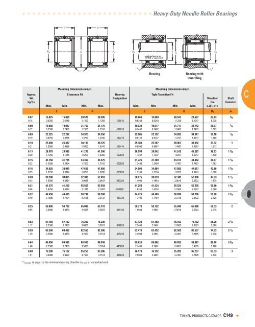
NEEDLE Roller BearingsInner RingsInch Series• Check for availabilty.• Ideal choice where shaft not practical to use as innerraceway.• Provided in inch nominal dimensions for use with inch seriesheavy-duty <strong>needle</strong> <strong>roller</strong> bearings.• Designed to meet established inch tolerances.• Selected size should be wider than matching drawn cupbearing.• Maximum shaft fillet radius (r as max) cannot exceed inner ringbore chamfer (r s min) as shown.• Optional centralized lubrication groove (bore) or through-holeavailable – specify when ordering.• Designed to be axially clamped against shoulder for loosetransition fit on shaft.• After mounting, for tight transition fit (keeping inner ring fromrotating relative to shaft), inner ring O.D. must not exceedraceway diameter on matching bearing.CShaft dimensions mm/in. Inner Ring I inner Ring U used WithDiameter D designation Approx. D designation BearingWt. Loose Transition Fit I interference Fit Designationkg/lbs. mm/in. mm/in.Max. Min. Max. Min.in. d F B r s min s s3 / 8 9.525 15.875 19.05 0.64 IR-061012 0.018 9.520 9.510 IR-061012 9.538 9.530 HJ-1018120.3750 0.6250 0.750 0.025 0.040 0.3748 0.3744 0.3755 0.37521 / 2 12.700 19.050 19.05 1.02 IR-081212 0.023 12.692 12.682 IR-081212 12.715 12.708 HJ-1220120.5000 0.7500 0.750 0.04 0.050 0.4997 0.4993 0.5006 0.500312.700 19.050 25.40 1.02 IR-081216 0.032 12.692 12.682 IR-081216 12.715 12.708 HJ-1220160.5000 0.7500 1.000 0.04 0.070 0.4997 0.4993 0.5006 0.50035 / 8 15.875 22.225 19.05 1.02 IR-101412 0.027 15.867 15.857 IR-101412 15.890 15.883 HJ-1422120.6250 0.8750 0.750 0.04 0.060 0.6247 0.6243 0.6256 0.625315.875 22.225 25.40 1.02 IR-101416 0.036 15.867 15.857 IR-101416 15.890 15.883 HJ-1422160.6250 0.8750 1.000 0.04 0.080 0.6247 0.6243 0.6256 0.625311 / 16 17.463 22.225 19.05 1.02 IR-111412 0.023 17.455 17.445 IR-111412 17.478 17.470 HJ-1422120.6875 0.8750 0.750 0.04 0.050 0.6872 0.6868 0.6881 0.68783 / 4 19.050 25.400 19.05 1.02 IR-121612 0.032 19.042 19.030 IR-121612 19.068 19.058 HJ-1624120.7500 1.0000 0.750 0.04 0.070 0.7497 0.7492 0.7507 0.750319.050 25.400 25.40 1.02 IR-121616 0.041 19.042 19.030 IR-121616 19.068 19.058 HJ-1624160.7500 1.0000 1.000 0.04 0.090 0.7497 0.7492 0.7507 0.750313 / 16 20.638 25.400 25.40 1.02 IR-131616 0.032 20.630 20.617 IR-131616 20.655 20.645 HJ-1624160.8125 1.0000 1.000 0.04 0.070 0.8122 0.8117 0.8132 0.81287 / 8 22.225 28.575 25.40 1.02 IR-141816 0.050 22.217 22.205 IR-141816 22.243 22.233 HJ-1826160.8750 1.1250 1.000 0.04 0.110 0.8747 0.8742 0.8757 0.875322.225 28.575 31.75 1.02 IR-141820 0.059 22.217 22.205 IR-141820 22.243 22.233 HJ-1826200.8750 1.1250 1.250 0.04 0.130 0.8747 0.8742 0.8757 0.875315 / 16 23.813 28.575 25.40 1.02 IR-151816 0.036 23.805 23.792 IR-151816 23.830 23.820 HJ-1826160.9375 1.1250 1.000 0.04 0.080 0.9372 0.9367 0.9382 0.937823.813 28.575 31.75 1.02 IR-151820 0.045 23.805 23.792 IR-151820 23.830 23.820 HJ-1826200.9375 1.1250 1.250 0.04 0.100 0.9372 0.9367 0.9382 0.93781 25.400 31.750 25.40 1.02 IR-162016 0.054 25.392 25.380 IR-162016 25.418 25.408 HJ-2028161.0000 1.2500 1.000 0.04 0.120 0.9997 0.9992 1.0007 1.000325.400 31.750 31.75 1.02 IR-162020 0.068 25.392 25.380 IR-162020 25.418 25.408 HJ-2028201.0000 1.2500 1.250 0.04 0.150 0.9997 0.9992 1.0007 1.00031 1 / 8 28.575 34.925 25.40 1.02 IR-182216 0.059 28.567 28.555 IR-182216 28.593 28.583 HJ-2230161.1250 1.3750 1.000 0.04 0.130 1.1247 1.1242 1.1257 1.125328.575 34.925 31.75 1.02 IR-182220 0.077 28.567 28.555 IR-182220 28.593 28.583 HJ-2230201.1250 1.3750 1.250 0.04 0.170 1.1247 1.1242 1.1257 1.12531 1 / 16 30.163 38.100 31.75 1.52 IR-192420 0.100 30.155 30.142 IR-192420 30.180 30.170 HJ-2433201.1875 1.5000 1.250 0.06 0.220 1.1872 1.1867 1.1882 1.18781 1 / 4 31.750 38.100 25.40 1.52 IR-202416 0.068 31.740 31.725 IR-202416 31.770 31.760 HJ-2433161.2500 1.5000 1.000 0.06 0.150 1.2496 1.2490 1.2508 1.250431.750 38.100 31.75 1.52 IR-202420 0.082 31.740 31.725 IR-202420 31.770 31.760 HJ-2433201.2500 1.5000 1.250 0.06 0.180 1.2496 1.2490 1.2508 1.25041 5 / 16 33.338 41.275 25.40 1.52 IR-212616 0.086 33.327 33.312 IR-212616 33.358 33.348 HJ-2635161.3125 1.6250 1.000 0.06 0.190 1.3121 1.3115 1.3133 1.3129Continued on next page.•C150 TIMKEN PRODUCTS CATALOG
Heavy-Duty Needle Roller BearingsDF WB• See tables for required bearing dimensions racewaydiameter.r a *r• After mounting, if O.D. of inner ring exceeds the requiredraceway diameter for matching bearing, ring should bed F Sground to proper diameter while mounted on shaft.• Unmarked end of inner ring to be assembled against the shaftshoulder to assure clearing the maximum allowable shaftfillet (r as max) as indicated in tables shown.rShaft dimensions mm/in. Inner Ring I inner Ring U used WithFa Diameter D SD Hdesignation a Approx. D designation BearingWt. Loose Transition Fit I interference Fit Designationshaft surface to be58 HRC or equivalentkg/lbs. mm/in. mm/in.Max. Min. Max. Min.in. d F B r s min s sr aF33.338 41.275 31.75 1.52 IR-212620 0.109 33.327 33.312 IR-212620 33.358 33.348 HJ-2635201.3125 1.6250 1.250 0.06 r a 0.240 1.3121 1.3115 S1.3133 1.3129d1 3 / 8 34.925 41.275 31.75 1.52 IR-222620 0.091 34.915 34.900 IR-222620 34.945 34.935 HJ-2635201.3750 1.6250 1.250 0.06 0.200 1.3746 1.3740 1.3758 1.375434.925 44.450 31.75 1.52 IR-222820 0.141 34.915 34.900 IR-222820 34.945 34.935 HJ-2837201.3750 1.7500 1.250 0.06 0.310 1.3746 1.3740 1.3758 1.3754r1 7 / 16 36.513 44.450 25.40 1.52 IR-232816 0.095 36.502 36.487 IR-232816 36.533 36.523 HJ-2837161.4375 re: Service 1.7500 Catalog, 1.000 pages 0.06408, 410, 411, 4120.210 1.4371 1.4365 1.4383 1.437936.513 44.450 31.75rev3 - 8Oct991.52 IR-232820 0.118 36.502 36.487 IR-232820 36.533 36.523 HJ-2837201.4375 1.7500 1.250 0.06 0.260 1.4371 1.4365 1.4383 1.43791 1 / 2 38.100 44.450 25.40 1.52 IR-242816 0.077 38.090 38.075 IR-242816 38.120 38.110 HJ-2837161.5000 1.7500 1.000 0.06 0.170 1.4996 1.4990 1.5008 1.500438.100 44.450 31.75 1.52 IR-242820 0.095 38.090 38.075 IR-242820 38.120 38.110 HJ-283720B 3d1.5000 1.7500 1.250 0.06 0.210 1.4996 1.4990 1.5008 1.500438.100 50.800 31.75 1.52 IR-243220 0.209 38.090 38.075 IR-243220 38.120 38.110 HJ-3241201.5000 2.0000 1.250 0.06 0.460 1.4996 1.4990 1.5008 1.50041 9 / 16 39.688 47.625 31.75 1.52 IR-253020 0.127 39.677 39.662 IR-253020D39.708 d4 39.698 HJ-3039201.5625 1.8750 1.250 0.06 0.280 1.5621 1.5615 1.5633 1.562939.688 50.800 31.75 1.52 IR-253220 0.186 39.677 39.662 IR-253220 39.708 39.698 HJ-3241201.5625 2.0000 1.250 0.06 0.410 1.5621 1.5615 1.5633 1.56291 5 / 8 41.275 50.800 31.75 1.52 IR-263220 0.163 41.265 41.250 IR-263220 41.295 41.285 HJ-3241201.6250 2.0000 1.250 0.06 0.360 1.6246 1.6240 1.6258 1.6254B 21 11 / 16 42.863 50.800 25.40 1.52 IR-273216 0.109 42.852 42.837 IR-273216 42.883 42.873 HJ-3241161.6875 2.0000 1.000 0.06 0.240 1.6871 1.6865 1.6883 1.687942.863 50.800 31.75 1.52 IR-273220 0.136 42.852 42.837 IR-273220 42.883 42.873 HJ-3241201.6875 2.0000 1.250 0.06 0.300 1.6871 1.6865 1.6883 1.6879re: Service Catalog, pages 4131 3 / 4 44.450 57.150 38.10 1.52 IR-283624 0.286 44.440 44.425 IR-283624 44.470 44.460 HJ-364824 rev1 - 20Sept991.7500 2.2500 1.500 0.06 0.630 1.7496 1.7490 1.7508 1.750444.450 57.150 44.45 1.52 IR-283628 0.336 44.440 44.425 IR-283628 44.470 44.460 HJ-3648281.7500 2.2500 1.750 0.06 0.740 1.7496 1.7490 1.7508 1.75041 15 / 16 49.213 63.500 38.10 2.03 IR-314024 0.358 49.202 49.187 IR-314024 49.233 49.223 HJ-4052241.9375 2.5000 1.500 0.08 0.790 1.9371 1.9365 1.9383 1.937949.213 63.500 44.45 2.03 IR-314028 0.417 49.202 49.187 IR-314028 49.233 49.223 HJ-4052281.9375 2.5000 1.750 0.08 0.920 1.9371 1.9365 1.9383 1.93792 50.800 63.500 38.10 2.03 IR-324024 0.322 50.790 50.772 IR-324024 50.823 50.810 HJ-4052242.0000 2.5000 1.500 0.08 0.710 1.9996 1.9989 2.0009 2.000450.800 63.500 44.45 2.03 IR-324028 0.376 50.790 50.772 IR-324028 50.823 50.810 HJ-4052282.0000 2.5000 1.750 0.08 0.830 1.9996 1.9989 2.0009 2.00042 3 / 16 55.563 69.850 44.45 2.03 IR-354428 0.467 55.552 55.535 IR-354428 55.585 55.573 HJ-4456282.1875 2.7500 1.750 0.08 1.030 2.1871 2.1864 2.1884 2.18792 1 / 4 57.150 69.850 38.10 2.03 IR-364424 0.358 57.140 57.122 IR-364424 57.173 57.160 HJ-4456242.2500 2.7500 1.500 0.08 0.790 2.2496 2.2489 2.2509 2.2504* *Continued on next page.ACTIMKEN PRODUCTS CATALOG C151•
NEEDLE Roller BearingsInner Rings – continuedInch Series• Check for availabilty.• Ideal choice where shaft not practical to use as innerraceway.• Provided in inch nominal dimensions for use with inch seriesheavy-duty <strong>needle</strong> <strong>roller</strong> bearings.• Designed to meet established inch tolerances.• Selected size should be wider than matching drawn cupbearing.• Maximum shaft fillet radius (r as max) cannot exceed inner ringbore chamfer (r s min) as shown.• Optional centralized lubrication groove (bore) or through-holeavailable – specify when ordering.• Designed to be axially clamped against shoulder for loosetransition fit on shaft.• After mounting, for tight transition fit (keeping inner ring fromrotating relative to shaft), inner ring O.D. must not exceedraceway diameter on matching bearing.CShaft dimensions mm/in. Inner Ring I inner Ring U used WithDiameter D designation Approx. D designation BearingWt. Loose Transition Fit I interference Fit Designationkg/lbs. mm/in. mm/in.Max. Min. Max. Min.in. d F B r s min s s57.150 69.850 44.45 2.03 IR-364428 0.417 57.140 57.122 IR-364428 57.173 57.160 HJ-4456282.2500 2.7500 1.750 0.08 0.920 2.2496 2.2489 2.2509 2.25042 3 / 8 60.325 76.200 44.45 2.03 IR-384828 0.562 60.315 60.297 IR-384828 60.348 60.335 HJ-4860282.3750 3.0000 1.750 0.08 1.240 2.3746 2.3739 2.3759 2.37542 1 / 2 63.500 76.200 38.10 2.03 IR-404824 0.395 63.490 63.472 IR-404824 63.523 63.510 HJ-4860242.5000 3.0000 1.500 0.08 0.870 2.4996 2.4989 2.5009 2.500463.500 76.200 44.45 2.03 IR-404828 0.463 63.490 63.472 IR-404828 63.523 63.510 HJ-4860282.5000 3.0000 1.750 0.08 1.020 2.4996 2.4989 2.5009 2.50042 3 / 4 69.850 82.550 44.45 2.03 IR-445228 0.503 69.840 69.822 IR-445228 69.873 69.860 HJ-5268282.7500 3.2500 1.750 0.08 1.110 2.7496 2.7489 2.7509 2.750469.850 82.550 50.80 2.03 IR-445232 0.576 69.840 69.822 IR-445232 69.873 69.860 HJ-5268322.7500 3.2500 2.000 0.08 1.270 2.7496 2.7489 2.7509 2.75042 15 / 16 74.613 88.900 50.80 2.03 IR-475632 0.694 74.602 74.585 IR-475632 74.635 74.623 HJ-5672322.9375 3.5000 2.000 0.08 1.530 2.9371 2.9364 2.9384 2.93793 76.200 88.900 50.80 2.03 IR-485632 0.621 76.190 76.172 IR-485632 76.223 76.210 HJ-5672323.0000 3.5000 2.000 0.08 1.370 2.9996 2.9989 3.0009 3.00043 1 / 8 79.375 95.250 50.80 2.54 IR-506032 0.880 79.365 79.347 IR-506032 79.398 79.385 HJ-6076323.1250 3.7500 2.000 0.1 1.940 3.1246 3.1239 3.1259 3.12543 1 / 4 82.550 95.250 50.80 2.54 IR-526032 0.708 82.537 82.517 IR-526032 82.578 82.563 HJ-6076323.2500 3.7500 2.000 0.1 1.560 3.2495 3.2487 3.2511 3.250582.550 101.600 50.80 2.54 IR-526432 1.089 82.537 82.517 IR-526432 82.578 82.563 HJ-6480323.2500 4.0000 2.000 0.1 2.400 3.2495 3.2487 3.2511 3.25053 3 / 8 85.725 101.600 50.80 2.54 IR-546432 0.930 85.712 85.692 IR-546432 85.753 85.738 HJ-6480323.3750 4.0000 2.000 0.1 2.050 3.3745 3.3737 3.3761 3.37553 1 / 2 88.900 101.600 50.80 2.54 IR-566432 0.757 88.887 88.867 IR-566432 88.928 88.913 HJ-6480323.5000 4.0000 2.000 0.1 1.670 3.4995 3.4987 3.5011 3.500588.900 107.950 50.80 2.54 IR-566832 1.179 88.887 88.867 IR-566832 88.928 88.913 HJ-6884323.5000 4.2500 2.000 0.1 2.600 3.4995 3.4987 3.5011 3.50053 3 / 4 95.250 107.950 50.80 2.54 IR-606832 1.012 95.237 95.217 IR-606832 95.278 95.263 HJ-6884323.7500 4.2500 2.000 0.1 2.230 3.7495 3.7487 3.7511 3.750595.250 114.300 57.15 2.54 IR-607236 1.406 95.237 95.217 IR-607236 95.278 95.263 HJ-7296363.7500 4.5000 2.250 0.1 3.100 3.7495 3.7487 3.7511 3.750595.250 114.300 63.50 2.54 IR-607240 1.565 95.237 95.217 IR-607240 95.278 95.263 HJ-7296403.7500 4.5000 2.500 0.1 3.450 3.7495 3.7487 3.7511 3.75054 101.600 127.000 57.15 2.54 IR-648036 2.046 101.587 101.567 IR-648036 101.628 101.613 HJ-80104364.0000 5.0000 2.250 0.1 4.510 3.9995 3.9987 4.0011 4.0005101.600 127.000 63.50 2.54 IR-648040 2.272 101.587 101.567 IR-648040 101.628 101.613 HJ-80104404.0000 5.0000 2.500 0.1 5.010 3.9995 3.9987 4.0011 4.00054 1 / 4 107.950 127.000 57.15 2.54 IR-688036 1.565 107.937 107.917 IR-688036 107.978 107.963 HJ-80104364.2500 5.0000 2.250 0.1 3.450 4.2495 4.2487 4.2511 4.25054 1 / 2 114.300 139.700 63.50 2.54 IR-728840 2.495 114.287 114.267 IR-728840 114.328 114.313 HJ-88112404.5000 5.5000 2.500 0.1 5.500 4.4995 4.4987 4.5011 4.5005Continued on next page.•C152 TIMKEN PRODUCTS CATALOG
Heavy-Duty Needle Roller BearingsDF WB• See tables for required bearing dimensions racewaydiameter.r a *r• After mounting, if O.D. of inner ring exceeds the requiredraceway diameter for matching bearing, ring should bed F Sground to proper diameter while mounted on shaft.• Unmarked end of inner ring to be assembled against the shaftshoulder to assure clearing the maximum allowable shaftfillet (r as max) as indicated in tables shown.rShaft dimensions mm/in. Inner Ring I inner Ring U used WithFa Diameter D SD Hdesignation a Approx. D designation BearingWt. Loose Transition Fit I interference Fit Designationshaft surface to be58 HRC or equivalentkg/lbs. mm/in. mm/in.Max. Min. Max. Min.in. d F B r s min s sr aF114.300 139.700 76.20 2.54 IR-728848 2.989 114.287 114.267 IR-728848 114.328 114.313 HJ-88112484.5000 5.5000 3.000 0.1 r a 6.590 4.4995 4.4987 S4.5011 4.5005d4 3 / 4 120.650 146.050 76.20 3.05 IR-769248 3.180 120.635 120.612 IR-769248 120.683 120.665 HJ-92116484.7500 5.7500 3.000 0.12 7.010 4.7494 4.7485 4.7513 4.75065 127.000 152.400 63.50 3.05 IR-809640 2.781 126.985 126.962 IR-809640 127.033 127.015 HJ-96120405.0000 6.0000 2.500 0.12 6.130 4.9994 4.9985 5.0013 5.0006r127.000 152.400 76.20 3.05 IR-809648 3.325 126.985 126.962 IR-809648 127.033 127.015 HJ-96120485.0000 re: Service 6.0000 Catalog, 3.000 pages 0.12408, 410, 411, 4127.330 4.9994 4.9985 5.0013 5.00065 1 / 2 139.700 165.100 63.50rev3 - 8Oct993.05 IR-8810440 3.035 139.685 139.662 IR-8810440 139.733 139.715 HJ-104128405.5000 6.5000 2.500 0.12 6.690 5.4994 5.4985 5.5013 5.5006139.700 165.100 76.20 3.05 IR-8810448 3.629 139.685 139.662 IR-8810448 139.733 139.715 HJ-104128485.5000 6.5000 3.000 0.12 8.000 5.4994 5.4985 5.5013 5.50066 152.400 184.150 76.20 3.05 IR-9611648 4.935 152.385 152.362 IR-9611648 152.433 152.415 HJ-11614648B 3d6.0000 7.2500 3.000 0.12 10.880 5.9994 5.9985 6.0013 6.00066 1 / 2 165.100 196.850 76.20 3.05 IR-10412448 5.343 165.085 165.062 IR-10412448 165.133 165.115 HJ-124154486.5000 7.7500 3.000 0.12 11.780 6.4994 6.4985 6.5013 6.50067 177.800 209.550 76.20 3.05 IR-11213248 5.389 177.785 177.762 IR-11213248D177.833 d4 177.815 HJ-132162487.0000 8.2500 3.000 0.12 11.880 6.9994 6.9985 7.0013 7.00067 1 / 2 190.500 222.250 76.20 4.06 IR-12014048 6.110 190.485 190.454 IR-12014048 190.536 190.515 HJ-140170487.5000 8.7500 3.000 0.16 13.470 7.4994 7.4982 7.5014 7.50068 203.200 234.950 76.20 4.06 IR-12814848 6.518 203.185 203.154 IR-12814848 203.236 203.215 HJ-148178488.0000 9.2500 3.000 0.16 14.370 7.9994 7.9982 8.0014 8.0006B 2* *ACre: Service Catalog, pages 413rev1 - 20Sept99TIMKEN PRODUCTS CATALOG C153•
NEEDLE Roller BearingsNOTESC•C154 TIMKEN PRODUCTS CATALOG
Stud Type and Yoke Type Track Rollerstrack <strong>roller</strong>sOverview: Track <strong>roller</strong>s (also known as cam followers) are characterized by their thick-walled outerrings that run directly on a track. The thick outer rings permit high load-carrying capability whileminimizing both distortion and bending stresses. Sealed designs with internal thrust washers helpextend service life under conditions of infrequent lubrication.• Sizes: 16 mm - 110 mm ( 1 / 2 in. - 4 in.) bore.• Markets: Ram support <strong>roller</strong>s, material handling and indexing equipment.• Features: Available in two basic designs: with an inner ring for straddle mountingin a yoke or with an integral stud for cantilever mounting.• Benefits: High load-carrying capability with minimized distortion and bending stresses.Extended service life under conditions of infrequent relubrication.CAFPOAFPOTIMKEN PRODUCTS CATALOG C155•
Yoke NEEDLE Type Track Roller Rollers Bearings – Metric Nominal DimensionsBore diameter from 10 mm to 17 mm (for NA22)00 = 10 mm 02 = 15 mm01 = 12 mm 03 = 17 mmBore diameter > 17 mm (for NA22)05 = 25 mmNA22 05 2rsCPrefixNA22 track <strong>roller</strong>, yoke type, profiled outsidediameter with inner ring, sealedRNA22 track <strong>roller</strong>, yoke type, profiled outsidediameter without inner ring, sealedRSTO track <strong>roller</strong>, yoke type, profiled outsidediameter without inner ring, without washersSTO track <strong>roller</strong>, yoke type, profiled outsidediameter with inner ring, without washersNATR track <strong>roller</strong>, yoke type, profiled outsidediameter with inner ring, with washersNUTR track <strong>roller</strong>, yoke type, profiled outsidediameter with inner ring, with washers;two paths of full complement cylindrical <strong>roller</strong>sSuffixTN molded cage of reinforced, engineered polymerDZ cylindrical outside diameterZZ two washers for track <strong>roller</strong>s used for axiallocation.2RS lip contact seal on each side of the bearingZZ.DZ two washers for track <strong>roller</strong>s used for axiallocation; cylindrical outside diameterDZ.TN cylindrical outside diameter; molded cage ofreinforced, engineered polymer.2RS.DZ lip contact seal on each side of bearing;cylindrical outside diameterSTO 25 DZBore diameter for STO, NATR, NUTR:25 = 25 mm45 = 45 mmNUTR 45 100 DZOutside diameter for NUTR100 = 100 mmStud Type Track Rollers – Metric Nominal DimensionsPrefix ModificationE Eccentric studSuffixSK hexagonal wrench socket in stud headDZ.2RS cylindrical outside diameter: lip contactseals on each end of bearing.2RS lip contact seal on each side of the bearingDZ cylindrical outside diameterAKR E 22 .2RSPrefixKR track <strong>roller</strong>, stud type with cage; profiled outside diameterKRV track <strong>roller</strong>, stud type, full complement <strong>needle</strong> <strong>roller</strong>s; profiled outside diameterNUKR track <strong>roller</strong>, stud type, full complement of cylindrical <strong>roller</strong>s (2 rows) profiled outside diameterTrack Rollers ⁄ Cam Followers – Inch Nominal DimensionsOutside diameter22 = 22 mmPrefixCR stud typeYCR yoke typeOutside Diameter8 = 8 ⁄ 16 = 1 ⁄ 2 in.16 = 16 ⁄ 16 = 1 in.CR S B E - 1632 = 32 ⁄ 16 = 2 in.36 = 36 ⁄ 16 = 2 1 ⁄ 4 in.•Design ModificationsS seals with internal thrust washers (CR Type only)B hex wrench socketC crowned O.D.E eccentric stud (CR Type only)C156 TIMKEN PRODUCTS SERVICE CATALOG
<strong>Full</strong> Complement Yoke Type Track Rollers - Metric Nominal DimensionsPrefixNUTR track <strong>roller</strong>, yoke type, profiled outside diameterwith inner ring and washers (two paths of cylindrical <strong>roller</strong>s)FG track <strong>roller</strong>, yoke type, profiled outside diameter standard seriesFGU track <strong>roller</strong>, yoke type, profiled outside diameter light seriesFGU track <strong>roller</strong>, yoke type, profiled outside diameter heavy series(larger O.D. than light series of same bore size)FP track <strong>roller</strong>, yoke type, profiled outside diameter small seriesRNA track <strong>roller</strong>, yoke type, profiled outside diameter 11000 Series(without seals)NUTR 45 100 .DZBore diameter45 = 45 mmOutside diameter100 = 100 mm(see tables fordimensions)RNA 110 12 B6Suffix.DZ cylindrical outside diameter (NUTR styles only)EE 2 polymer shields (FG styles only)EEM 2 metal shields (FG styles only)MM 2 metal shields (FGU styles only)CCAFG L 6 19 EEMPrefix ModificationL cylindrical outside diameter<strong>Full</strong> Complement Stud Type Track Rollers - Metric Nominal DimensionsPrefixNUKR track <strong>roller</strong>, stud type, profiled outside diameter(two paths of cylindrical <strong>roller</strong>s)KRV track <strong>roller</strong>, stud type, profiled outside diameterwith full complement of <strong>needle</strong> <strong>roller</strong>sGC track <strong>roller</strong>, stud type, profiled outside diametersmall series (up to 15 mm O.D.), standard seriesGCU track <strong>roller</strong>, stud type, profiled outside diameterlight seriesOutside diameter16 = 16 mmKRV 16 .DZNUKR 62 .2SKGC L 6 19 EEMAPrefix ModificationL cylindrical outside diameterR eccentric collarBore diameter45 = 45 mmSuffix.DZ cylindrical outside diameter (KRV styles only).2SK hexagonal socket in stud head (NUKR styles only)EE 2 polymer shields (GC, GCR styles only)EEM 2 metal shields (GC, GCR styles only)MM 2 metal shields (GCU, GCUR styles only)TIMKEN PRODUCTS SERVICE CATALOG C157TIMKEN SERVICE CATALOG C157• • •
CCA•C158 TIMKEN PRODUCTS CATALOG
Stud Type and Yoke TypeTrack RollersSTUD TYPE AND YOKE TYPE TRACK ROLLERSMETRIC SERIESPageIntroduction.............................................................................. C160STUD TYPE Metric SeriesNeedle Roller and Cage Assemblies (KR Series)................... C168Needle Roller and Cage Assemblies, Sealed(KR….2S Series)................................................................. C170<strong>Full</strong> Complement with Needle Rollers (KRV Series) orCylindrical Rollers (NUKR Series).................................... C172<strong>Full</strong> Complement, Small Series, Unsealed (GC Series)........ C174<strong>Full</strong> Complement, Standard Series, with orwithout Seals (GC Series)................................................ C176<strong>Full</strong> Complement, with Metal Seals (GCU…..MM Series).... C178<strong>Full</strong> Complement, Eccentric (GCR Series).............................. C180<strong>Full</strong> Complement Eccentric, with Metal Seals(GCUR…..MM Series)........................................................ C184YOKE TYPE METRIC SERIESCaged, without Inner Ring, No End Washers(RSTO Series)..................................................................... C186Caged, with Inner Ring, No End Washers (STO Series)....... C188Caged, without Inner Ring, No End Washers,Sealed (RNA22 Series)...................................................... C190Caged, with Inner Ring, No End Washers,Sealed (NA22 Series)........................................................ C192Caged, with Inner Ring, With End Washers(NATR, STO.ZZ Series)...................................................... C194<strong>Full</strong> Complement, with Inner Ring, with End Washers,Cylindrical Rollers (NUTR Series).................................... C196....................................................................................................... Page<strong>Full</strong> Complement, Non-Separable, Small Series,Unsealed (FP Series)......................................................... C198<strong>Full</strong> Complement, Non-Separable, Sealed or Unsealed(FG Series).......................................................................... C199<strong>Full</strong> Complement, Non-Separable, Light Series,with Metal Seals (FGU…..MM Series)............................. C202<strong>Full</strong> Complement, Non-Separable, Heavy Series,with Metal Seals (FGU…..MM Series)............................. C203<strong>Full</strong> Complement, without Inner Ring, Unsealed(RNA…..B6, RNAB, RNAL Series)..................................... C205Separate Inner Rings for RNA…..B6, RNAB,RNAL Series (BIC Series).................................................. C205STUD TYPE AND YOKE TYPE TRACK ROLLERS ....................................INCH SERIESIntroduction.............................................................................. C206Stud Type Track Rollers CR, CRS Series................................ C212Stud Type Track Rollers CRSB Series..................................... C216Yoke Type Track Rollers YCR, YCRS Series........................... C220CAATIMKEN PRODUCTS CATALOG C159•
NEEDLE Roller BearingsCStud Type And Yoke Type Track Rollers –Metric SeriesTimken track <strong>roller</strong>s listed in this catalog have been designedwith outer rings of a large radial cross section to withstand heavyrolling and shock loads on track type or cam-controlled equipment.The outside diameters of the outer rings are either profiled orcylindrical. Profiled track <strong>roller</strong>s are designed to alleviate unevenbearing loading resulting from deflection, bending or misalignmentin mounting.Stud type track <strong>roller</strong>s are available in various open designs,as well as with lip contact seals or metal shields.Yoke type track <strong>roller</strong>s are designed for straddle mounting.The various metric series designs are grouped and organized asillustrated below.Reference standards are:• ISO 6278 – Needle <strong>roller</strong> bearings – Track <strong>roller</strong>s –Boundary dimensions• ISO 492 – Radial bearings – Tolerances• DIN 620 – Tolerances of Ball and Roller Bearings• ISO 281 – Rolling bearings – Dynamic load ratingsand rating lifeASuffixes – Stud Type, Metric Series (except GC types).2RStwo sealsDZcylindrical outside diameterDZ.2RS cylindrical outside diameter • two sealsSKhexagonal socket in flange end2SKhexagonal socket in both flange and stud endsSuffixes – Yoke Type, Metric Series (except FP or FG types)DZ.TNcylindrical outside diameter • molded cage of reinforced engineered polymerTNmolded cage of reinforced engineered polymerDZcylindrical outside diameterZZtwo end washers for the outer ringZZ.DZtwo end washers for the outer ring • cylindrical outside diameter.2RStwo seals.2RS.DZ two seals • cylindrical outside diameterSuffixes – Yoke Type (FP, FG) and Stud Type (GC)EEpolymer sealsEEMmetal shieldsMMmetal shields•C160 TIMKEN PRODUCTS CATALOG
Stud Type and Yoke Type Track RollersKRStud Type Metric series Track Roller TypesKR.BKR.CKR.DZKR.B.DZKR.C.DZStud type track <strong>roller</strong>s, caged <strong>needle</strong> <strong>roller</strong>sKRKR.BKR.Ckr kr.DZ KR.2RS KR.DZ.2RSKR.DZKR.B.DZKR.C.DZKR.B.2RSKR.C.2RSKR.B.DZ.2RSKR.C.DZ.2RSCAStud type track <strong>roller</strong>s, full complement <strong>needle</strong> <strong>roller</strong>sPage 131-1rev1.26Jan99KR.B.2RSKR.C.2RSKR.B.DZ.2RSKR.C.DZ.2RSKRVkrVKRV.DZkrV.DZPage 131-1rev1.26Jan99GC/GCL GC/GCL GCR/GCRLKRVKRV.DZNUKR.AANUKR.AA.DZAGC...series:Stud type track <strong>roller</strong>s, GC...EE series: withoutfull with plasticsealscomplement sealscylindrical <strong>roller</strong>sGC...EEM series: with metal sealsPage 131-2rev4.25Feb99NUKR.AANUKR.AA.DZnukr NUKR.DZ GCU/GCUL GCUR/GCURLPage 131-2rev4.25Feb99TIMKEN PRODUCTS CATALOG C161•
NEEDLE Roller BearingsTypes of Metric Series Yoke Type Track RollersYoke type track <strong>roller</strong>s without end washersCrsto rsto.DZ sto sto.DZRSTO RSTO.DZ STORSTO.DZ RSTO.DZ RSTO.DZ STO.DZSTO.DZRSTO RSTO.DZ STORSTO.DZ RSTO.DZ RSTO.DZ STO.DZSTO.DZSealed yoke type track <strong>roller</strong>s without end washers.RNA22.2RSRNA22.2RS.DRNA22.2RS.DNA22.2RS.DZRNA22.2RS.DNA22.2RS.DZRNA22.2RS.DNA22.2RS.DZNA22.2RS.DZZZZZRNA22.2rs rna22.2RS.DZ na22.2rs na22.2RS.DZRNA22.2RSRNA22.2RS.DRNA22.2RS.DNA22.2RS.DZRNA22.2RS.DRNA22.2RS.DNA22.2RS.DZNA22.2RS.DZNA22.2RS.DZZZZZPage 109-1Page 109-1 rev0.Nov98 Page 109-1Yoke type track <strong>roller</strong>s Page 109-1 with end Page washers109-1 rev0.Nov98 Page 109-1rev0.Nov98 Page 109-1 rev0.Nov98rev0.Nov98Yoke type track <strong>roller</strong>s with fullcomplement of cylindrical <strong>roller</strong>srev0.Nov98 Page 109-1rev0.Nov98rev0.Nov98Anatr natr.DZ sto.ZZ sto.ZZ.DZNATR NATR NATR NATR NATR.DZ NATR.DZ NATR.DZ NATR.DZ ST0.ZZ ST0.ZZ ST0.ZZ ST0.ZZ STO.ZZ.DZ STO.ZZ.DZ STO.ZZ.DZ STO.ZZ.DZFGU/FGUL LightFGU/FGUL HeavyNATR NATR NATR.DZ NATR.DZ ST0.ZZ ST0.ZZ STO.ZZ.DZ STO.ZZYoke type track <strong>roller</strong>s with end washers, full complement of <strong>needle</strong> <strong>roller</strong>sNUTR NUTR NUTR NUTRNUTR.DZ NUTR.DZ NUTR.DZ NUTR.DZFP/FPL FG/FGl rna1100 NUTRnutr NUTR NUTR.DZ NUTR.DZ nutr.DZPage Page 109-2 Page 109-2 Page 109-2 109-2rev0.Nov98rev0.Nov98RNA...B6•C162 TIMKEN PRODUCTS CATALOGPage 109-2 Page 109-2rev0.Nov98
ConstructionStud Type Track RollersThe metric series stud type track <strong>roller</strong> is a non-separableunit, consisting of a large radial cross-section outer ring, <strong>needle</strong><strong>roller</strong> and cage radial assembly or a full complement of <strong>needle</strong> orcylindrical <strong>roller</strong>s, a stud and a retaining washer securely fastenedto the stud.The seals on the sealed stud type track <strong>roller</strong>s are located in thecounterbores of the outer ring and seal against the stud flange and theretaining washer, providing good retention of lubricant and exclusionof foreign material. The seals are thermally stable in a temperaturerange between -30˚ C and 110˚ C.A screwdriver slot (standard) or a hexagonal wrench socket(customer requested) in the head of the stud facilitates mounting.Wrench sizes are listed on the dimensional tables where found amongcertain GC Series sizes on pages later in this section. Other metricseries hexagonal socket sizes are listed in Table 1.Stud Type and Yoke Type Track RollersSome applications may require more secure positioning thanprovided by the tightened stud nut. If so, it is recommended thatthe mounting hole and the eccentric bushing be drilled at the timeof installation to accept a locating dowel pin.B ee De SW80 90 30 35 29 1.5tTable 1 –Hexagonal Socket – Metric SeriesTable 2 –Eccentric Bushing Dimensions –Stud Type Track RollerdimensionsMetric Series (except GCR, GCUR series)Outside DiameterStud Type Track Roller> ≤ sw tOutside Diameter mm dimensionsmm> ≤16 3 2.5d e D e B e e19 26 4 2.516 6 9 7 0.530 35 6 419 19 8 11 9 0.540 52 8 522 26 10 13 10 0.562 72 12 730 32 12 15 11 0.580 90 17 1035 35 16 20 14 1.040 40 18 22 16 1.047 52 20 24 18 1.0B eSWCAd ee DePage 132Table 2A -Eccentric Bushing DimensionsMetric Series GCR, GCurEccentric Studs For Stud Type Track RollersTo provide radial adjustment of the outer ring toward the track orcam surface at the time of installation, some metric series stud typetrack <strong>roller</strong>s are available with eccentric studs which are specifiedby adding the letter “E” to the designation letters: KRE and NUKRE.The GCR and GCUR Series include an eccentric bushing added tothe track <strong>roller</strong> stud. Appropriate dimensions of the eccentric studbushing are listed in Table 2 and 2A.Since a track <strong>roller</strong> with an eccentric stud is usually adjustedupon installation by turning the stud in the mounting hole, a closeclearance fit between the outside diameter of the bushing andthe mounting hole is necessary. For turning the stud, a hexagonalwrench is generally more convenient than a screwdriver, thus,the option of a hexagonal wrench socket in the head of the studshould be considered.tover incl. de De Bw emm- 19 6 9 7.5 0.519 28 10 14 10.5 1.028 32 12 16 11.5 1.032 35 16 21 15.1 1.535 40 18 24 17.1 1.540 52 20 27 19.1 2.052 72 24 36 24.1 3.072 90 30 42 30.7 3.090 110 36 48 36.5 3.0110 - 42 54 43.5 3.0ATIMKEN PRODUCTS CATALOG C163•
CANEEDLE Roller BearingsYoke Type Track RollersMetric Series Yoke Type Track RollersWithout End WashersThese yoke type track <strong>roller</strong>s are available with a profiled or acylindrical outside diameter of the outer ring, and with or without aseparable inner ring. Since they are supplied without end washers,their outer rings must be guided by the adjacent end locatingsurfaces. Tolerance class F6 is the normal specification for thebore of the metric series <strong>needle</strong> <strong>roller</strong> and cage radial assembliesused with these yoke type track <strong>roller</strong>s.Yoke Type Track Rollers – Series RSTO & STOSeries STO have a separable inner ring and when the innerring is removed they become series RSTO. They run directly on ahardened and ground inner raceway. Quality requirements for innerraceways are given in the engineering section of this catalog.Sealed Yoke Type Track Rollers Without EndWashers – Series RNA 22.2RS & NA22.2RSThese yoke type track <strong>roller</strong>s have the same bore diameter andoutside diameter as most of the other metric series yoke type track<strong>roller</strong>s listed in this catalog. The thick section outer ring is madeof one-piece channel-shaped bearing quality steel, heat treated toyield maximum load carrying capability. The integral end flangesprovide axial guidance for the large diameter <strong>needle</strong> <strong>roller</strong>s, anda cage supplies their inward retention. These track <strong>roller</strong>s havetwo integral lip contact seals designated by .2RS. The seals arethermally stable in a temperature range between -30° C and 110° C.Care should be exercised when mounting track <strong>roller</strong>s withoutinner rings onto inner raceways to avoid damage to the seals.Inner raceway quality requirements are given in the engineeringsection of this catalog.Metric Series Yoke Type Track Rollers WithEnd WashersThese yoke type track <strong>roller</strong>s are available with a crowned ora cylindrical outside diameter of the outer ring. Metric series yoketype track <strong>roller</strong>s with end washers, depending on the internalconstruction, may be end guided, either through the end washersor between the end faces of the <strong>roller</strong>s and the inside faces of theouter ring flanges.Yoke Type Track Rollers – Series NATR & STO.ZZThe series NATR yoke type track <strong>roller</strong>s are of non-separabledesign consisting of a crowned or a cylindrical outer ring, caged<strong>needle</strong> <strong>roller</strong>s, an inner ring and two retaining end washers securelyfastened to the inner ring. The series STO.ZZ yoke type track <strong>roller</strong>sare of separable design with two loose end washers. These endwashers placed in the counter bores of the outer ring form veryeffective labyrinth type shields, providing good retention of lubricantand exclusion of foreign material. A lubrication hole in the innerring enables relubrication when a cross-drilled bolt or shaft, whichcan be serviced from the end, is used.Yoke Type Track Rollers – Series NUTRThe series NUTR yoke type track <strong>roller</strong>s are of non-separabledesign consisting of a profiled or cylindrical outer ring, two rows offull complements of cylindrical <strong>roller</strong>s, an inner ring, two retainingend washers and two shields. The outer ring is located axiallythrough the cylindrical <strong>roller</strong>s.A lubricating hole in the inner ring enables relubrication whena cross-drilled bolt or shaft, which can be serviced from the end,is used.The smallest track <strong>roller</strong> of this series has an outside diameterof 35 mm. NUTR yoke type track <strong>roller</strong>s are well suited to carryhigh loads and designs with a thicker outer ring are particularlysuitable for high shock loads. Designs with thicker outer ring havea larger outside diameter which can be identified by the bearingdesignation (e.g., NUTR 1542).Yoke type track <strong>roller</strong>s – series FP and FGThe FP and FG non-separable inner ring designs are available inprofiled or cylindrical outer rings. Both employ a full complementof <strong>needle</strong> <strong>roller</strong>s and require relubrication via a pathway throughthe shaft. The FP Series is the smallest series available and is notoffered with seals.Yoke type track <strong>roller</strong>s – series FGU(Light and Heavy types)The FGU non-separable inner ring desings are availablein profiled or cylindrical outer rings. All FGU Series use a fullcomplement of cylindrical <strong>roller</strong>s between the inner and outer ringsand require relubrication via a pathway through the shaft. The FGUHeavy series uses a thicker outer ring section and are capable ofhigher loads.Both FGU Series are only available with a metal shield for a<strong>roller</strong> sealing option.Yoke type track <strong>roller</strong>s – series RNA, RNAB,RNALThe RNA and RNAB Series design use a full complement of<strong>needle</strong> <strong>roller</strong>s retained with a pair of end washers. A separate,matching inner ring is listed in the tables of part numbers. TheRNAL Series use a cylindrical outer ring and is only offered inlimited sizes.•C164 TIMKEN PRODUCTS CATALOG
Stud Type and Yoke Type Track RollersDimensional AccuracyThe tolerances of the basic metric series caged <strong>roller</strong> and NUKRstud type and yoke type track <strong>roller</strong>s whose outer rings have acylindrical outside diameter, correspond to tolerances specifiedin ISO-492 Radial bearings - Tolerances. The outer ring tolerancesgiven in Table 4 apply to the outer rings used in the caged <strong>roller</strong> andNUKR stud type and caged <strong>roller</strong> and NUTR yoke type, metric series,track <strong>roller</strong>s. Metric series track <strong>roller</strong>s with a crowned outsidediameter are the exception: their outside diameter tolerances is 0-0.05 for all caged <strong>roller</strong> sizes and NUTR, NUKR types. The remainingtypes have h9 tolerance on profiled outer diameters and h7 forstraight diameters. Stud diameter and stud length tolerances areTable 3 –Tolerances For Stud Diameter And Stud Length– Metric SeriesStud Diameter mmStud Length mmµm> ≤ high low high lowd 1 ∆d 1S B 2 ∆B 23 6 0 -126 10 0 -15 all10 18 0 -18 lengths 0 -118 30 0 -2130 50 0 -2550 80 0 -3080 100 0 -35given in Table 3. The inner ring tolerances given in Table 5 apply toinner rings used in metric series caged <strong>roller</strong>, NUKR Series yoketype track <strong>roller</strong>s.Mounting Stud Type Track RollersWhen the stud shank of a metric series stud type track <strong>roller</strong> ismounted in a hole of tolerance H7, the installation force should beapplied only to the center portion of the flanged end of the stud,preferably with an arbor press. The surface of the hole in themachine element which supports the stud must not deform underthe expected load, and the support should be sufficiently rigid toresist bending loads. Deformation and bending will cause unevenloading of the outer ring.In mounting the stud type track <strong>roller</strong>, the retaining washer mustbe firmly backed up by a flat shoulder which is square with the studcenter line. The shoulder diameter must be no smaller than theminimum clamping diameter, d a listed in the tabular data.The maximum inherent strength of the stud is obtained whenthe track <strong>roller</strong> is supported as close as possible to the retainingwasher, which minimizes the bending moment. For this reason theedge of the housing which supports the stud shank should be keptas sharp as practical, but free from burrs.The clamping nut should not be tightened with a torque valuehigher than the maximum listed. A screwdriver slot or hexagonalwrench socket in the flanged end of the stud is provided for a toolto prevent the stud from turning when the nut is being tightened.Hexagonal nuts are supplied with all metric series stud type track<strong>roller</strong>s.CATable 4 –Outer Ring – Metric Series (Caged <strong>roller</strong> and nukr, nutr types)Tolerances in mm (0.001 mm)mm> ≤ cylindrical crownedhigh low high low high low max.D ∆ Dmp ∆ Cs k ea10 18 0 -8 0 -50 0 -120 1518 30 0 -9 0 -50 0 -120 1530 50 0 -11 0 -50 0 -120 2050 80 0 -13 0 -50 0 -120 2580 120 0 -15 0 -50 0 -120 35120 150 0 -18 0 -50 0 -120 40150 180 0 -25 0 -50 0 -150 45180 240 0 -30 0 -50 0 -200 50ATable 5 – Inner Ring – Metric Series (Caged <strong>roller</strong> and nutr types)Tolerances in mm (0.001 mm)mm> ≤ high low high lowd ∆ dmp ∆ Bs2.5 18 0 -8 0 -18018 30 0 -10 0 -21030 50 0 -12 0 -25050 80 0 -15 0 -30080 120 0 -20 0 -350TIMKEN PRODUCTS CATALOG C165•
NEEDLE Roller BearingsCYoke Type Track RollersThe machine element with the holes in which the mountingbolt or shaft is supported must be sufficiently rigid to resist localcrushing under the applied load, and to resist bending which cancause uneven loading of the <strong>needle</strong> <strong>roller</strong>s.When applied loads are high, the h6 or j6 tolerance should beused in conjunction with a high strength shaft or bolt for mountingmetric series yoke type track <strong>roller</strong>s. When loads are moderate,a g6 tolerance may be used with a high strength shaft or bolt. Forlight loads, the loose transition fit with the f6 tolerance may be usedwith an unhardened shaft or bolt.The yoke type track <strong>roller</strong>s with inner rings, also those withend washers as well as inner rings, should be clamped endwisebetween parallel faces perpendicular to the axis to prevent theretaining washers from coming off under load. The dimensions ofmachine parts adjoining the metric series yoke type track <strong>roller</strong>sshould be based on the minimum clamping diameter d a to ensurethat the washers are adequately supported. If the track <strong>roller</strong>cannot be end clamped, a close axial fit in the yoke is required.Care should be taken that the lubricating hole is located in theunloaded zone of the raceway.The metric series yoke type track <strong>roller</strong>s without inner ringsrequire a hardened and ground shaft or bolt with a k5 tolerance.Inner raceway quality requirements are given in the engineeringsection of this catalog.ALoad RatingsDynamic Loading As A Track RollerWhen the outer ring of a stud type or yoke type track <strong>roller</strong>runs on a track, the contact, under a radial load, causes elastic(oval) deformation of the outer ring. As a result, a smaller zone ofthe raceway is loaded and the load is distributed on fewer <strong>needle</strong><strong>roller</strong>s. This in turn affects the dynamic and static load ratings ofthe track <strong>roller</strong>s. Also, this deformation generates bending stressin the outer ring which must not exceed the maximum permitted forthe material of the outer ring. The maximum permissible dynamic(F r perm) radial load condition is determined by this requirement.The rating life of stud type or yoke type track <strong>roller</strong>s should becalculated using the dynamic load ratings C w shown in the tables.The tables also show the maximum permissible radial load, F r permthat can be dynamically applied on stud type or yoke type track<strong>roller</strong>s. However, to calculate the L 10 life of a track <strong>roller</strong>, theapplied radial load must not be greater than C w/2 based on idealoperating conditions of alignment, lubrication, temperature, speed,and accelerations.Static Rating As A Track RollerIn addition to the basic static load rating C 0, the tables also listthe maximum permissible static radial load F 0r perm that may beapplied to a stud type or yoke type metric series track <strong>roller</strong>. Thevalues of F 0r perm result in a calculated minimum static factor f s of 0.7for the worst condition of internal load distribution in metric seriestrack <strong>roller</strong> operation. The F 0r perm values must not be exceeded. Thestatic factor f s can be calculated using the following formula:f s ≥F0.7 • 0r permwhereF 0r permP 0rF 0rf s= Maximum permissible static radial load (kN)= Equivalent static load (kN)P 0r = F 0r for metric series track <strong>roller</strong>s= Static radial load (kN)= Static factor whose values should not besmaller than those suggested in Table 6.Table 6 –suggested Values For Static Factors f s For Metric SeriesTrack RollersRequirements For Yoketype Track Rollers And Studtype Track RollersP 0rsuggested f s ValuesHigh shock-type loadsQuiet running 1.5...2.5Normal loadingNormal quietness ofrunning 1...1.5Minor impact loads androtary motion particularlyquiet running not required 0.7...1•C166 TIMKEN PRODUCTS CATALOG
Stud Type and Yoke Type Track RollersLubrication Of Stud TypeTrack RollersTimken metric series stud type track <strong>roller</strong>s are supplied with alithium soap based, general purpose grease. When the caged KRSeries track <strong>roller</strong>s are operated at low speeds, with light loadsand in clean environments, there often is no need to relubricatethe track <strong>roller</strong>. In other applications, periodic relubrication maybe necessary to obtain optimum performance. The full complementseries of track <strong>roller</strong>s have less internal volume available forgrease storage, therefore, they may require more frequentlubrication than caged type track <strong>roller</strong>s. Stud type track <strong>roller</strong>s,with a screwdriver slot in the flanged end of the stud, haveprovisions for relubrication through the flanged end of the stud.Metric series stud type track <strong>roller</strong>s with hexagonal sockets cannot be relubricated from the flanged end of the stud. Both types ofmetric series stud type track <strong>roller</strong>s, with outside diameters largerthan 22 mm (28 mm for all GC variations), allow for relubricationthrough the threaded end of the stud. In addition, caged <strong>roller</strong> andNUKR Series stud type track <strong>roller</strong>s with 30 mm and larger outsidediameters allow for relubrication through a cross-drilled hole in thestud shank. The ends of the axial holes are counterbored to acceptpress-fit grease fittings of series VENN. The grease fittings aresupplied with metric series stud type track <strong>roller</strong>s. Hole diameters(d 4) for these grease fittings are listed in the tables of dimensionson pages later in this chapter as it applies. Note that the GC smallseries has no axial hole.One or more plugs are supplied with every metric series studtype track <strong>roller</strong> to close off unused holes. At the flanged end,the plug must not be pushed in too deeply as it may cover thecross-drilled lubricating hole. The plug should be pressed in usingan installation tool whose dimensions are given in Table 8. If thecross-drilled hole in the stud shank is not used, it will be coveredwhen the track <strong>roller</strong> is properly installed.t 1-0,1d D-0,1 d 4-0,1d E-0,1t +0,2During installation of the track <strong>roller</strong> it will be desirable to ensurethat the cross drilled hole is positioned in the unloaded zone of thetrack <strong>roller</strong> raceway. The location of the cross-drilled hole can bebest recognized by its alignment with the manufacturer's stampor parallel to the screwdriver slot, in certain cases.Lubrication Of Yoke TypeTrack RollersYoke type track <strong>roller</strong>s are produced with a lubricating hole inthe inner ring so they can be relubricated through a cross-drilledhole in the supporting shaft or bolt. When mounting yoke type track<strong>roller</strong>s, care should be taken that the lubrication hole is located inthe unloaded raceway zone.Oil is the preferred lubricant for yoke type track <strong>roller</strong>s.Continuous oil lubrication or frequent grease lubrication should beused for steady rotating conditions. Applications involving slow,intermittent oscillations are not as critical, and longer intervalsbetween relubrication are permitted. Sealed yoke type track<strong>roller</strong>s are normally supplied with an initial charge of a mediumtemperature grease. Caged yoke type track <strong>roller</strong>s have maximumgrease storage capacity and, consequently, longer pregreased lifethan full complement types.CAd 4H 1D kHATable 7 – Metric Series Grease Fittings, Series VENNDesignation Dimensions mm wt. gapprox.d 4 D K H H 1VENN 4 4 6 6 1.5 0.4VENN 6 6 8 7 2 1.6VENN 8 8 10 12 3 4.7Table 8 – Installation Tool For Metric Series PlugStud Typedimensionstrack Rolleroutsidediameter mm> ≤ d 4 d D d E t t 116 26 3.9 10 2.7 3.7 4.530 40 5.9 12 4.7 4.7 747 90 7.9 15 6.7 6.7 10TIMKEN PRODUCTS CATALOG C167•
NEEDLE Roller BearingsD d a d 4 d 1 d 4 GG 1B 2KRKR.BKR.CNeedle Roller and Cage Assemblies,Stud type (KR Series)Metric SeriesrCrCC 1B 1B 3d 3R500B 3d 3D d a d 4 d 1 d 4 GG 1B 2KRD KR.B d a d 4 d 1d 4KR.CGKR.DZKR.B.DZKR.C.DZCAC 1B 1KRL 2 C B 3rd ard 3R500Outer D dimensions mm/in.Dia.KR.DZThreadD D a d 1 d h d 1D KR.B.DZ d a d 4 d 1d 4mm d 1 h 7 C r s min B 1 B 2 B 3 G 1 KR.C.DZd 4 d 3 G C 116 6 16 11 0.3 28.2 16 8 4 M6x1 0.60.2362 0.6299 0.433 0.012 1.110 0.630 0.315 0.157 0.0246 16 11 0.3 28.2 16 8 4 C M6x1 10.6 G 10.2362 0.6299 0.433 0.012 C 1.110 0.630 0.315 0.157 0.024sB 219 8 19 11 0.3 32.2L20 10 4 M8x1.25 0.6B0.3150 0.7480 0.433 0.012 1.268 1L0.787 0.394 0.157 0.02428 19 11 0.3 32.2 20 10 4 M8x1.25 0.6r0.3150 0.7480 0.433 0.012 1.268d0.787 a0.394 0.157 0.02422 10 22 12 R500 0.3 36.0 23 12 4 M10x1 0.60.3937 0.8661 0.472 0.012 1.417 0.906 0.472 0.157 0.024KR.B.2RS10 22 12 D D a d0.3 36.2 1 d h23 d 1 G 12 4 M10x1 0.6KR.C.2RS0.3937 0.8661 0.472 0.012 1.425 0.906 0.472 0.157 0.024300.3937 1.0236 0.472 0.012 1.425 0.906 0.472 0.157 0.024CLs112 30 14 0.6 40.0 25 6 13 Page 136/138 6 3 M12x1.5 0.6Lrev3.26Jan990.4724 1.1811 0.551 0.024 1.575 0.984 0.236 0.512 0.236 0.118 0.02410 26 12 0.3 36.2 23 L 3 12 4 M10x1 0.626 10 26 12 0.3 36.0 23 12 4 M10x1 0.60.3937 1.0236 0.472 0.012 1.417 0.906 0.472 0.157 0.024L 1L 3GC 1B 1KR.DZB 2G 112 30 14 0.6 40.2 25 6 13 6 3 M12x1.5 0.60.4724 1.1811 0.551 0.024 1.583 0.984 0.236 0.512 0.236 0.118 0.02432 12 32 14 0.6 40.0 25 6 13 6 3 M12x1.5 0.60.4724 1.2598 0.551 0.024 1.575 0.984 0.236 0.512 0.236 0.118 0.02412 32 14 0.6 40.2 25 6 13 6 3 M12x1.5 0.60.4724 1.2598 0.551 0.024 1.583 0.984 0.236 0.512 0.236 0.118 0.024GKR.B.2RKR.C.2RPage 136/138•C168 TIMKEN PRODUCTS CATALOG
Dd a d 4 d 1 d 4G 1B 2GKR.DZKR.B.DZKR.C.DZStud Type and Yoke Type Track RollersC 1B 1DC B 3rd 3R500d a d 4 d 1d 4GKR.B.2RSKR.C.2RSC 1KR.2RSB 2G 1Page 136/138B 1Load Ratings kN/lbf. tightening Limitingrev4.25Feb99CABearing as a Track Roller torque Speed wt.designation Dynamic Static Dynamic static Nm/in.-lbs. Grease kg/lbs.d a C C o C w F r perm F Or perm RPM11 KR16 3.60 3.58 2.97 2.85 3.58 7 17000 0.0190.433 810 800 670 640 800 62.0 0.04211 KR16.DZ 3.60 3.58 2.97 2.85 3.58 7 17000 0.0190.433 810 800 670 640 800 62.0 0.04213 KR19 4.18 4.65 3.28 3.29 4.22 16 13000 0.0310.512 940 1050 740 740 950 142 0.06813 KR19.DZ 4.18 4.65 3.28 3.29 4.22 16 13000 0.0310.512 940 1050 740 740 950 142 0.06815 KR22 5.35 6.79 3.94 4.04 5.45 28 10000 0.0460.591 1200 1530 890 910 1230 248 0.10115 KR22.DZ 5.35 6.79 3.94 4.04 5.45 28 10000 0.0460.591 1200 1530 890 910 1230 248 0.10115 KR26 5.35 6.79 4.55 6.78 7.24 28 10000 0.0590.591 1200 1530 1020 1520 1630 248 0.13015 KR26.DZ 5.35 6.79 4.55 6.78 7.24 28 10000 0.0590.591 1200 1530 1020 1520 1630 248 0.13021 KR30 7.89 9.79 6.32 7.74 9.31 45 8200 0.0870.827 1770 2200 1420 1740 2090 398 0.19221 KR30.DZ 7.89 9.79 6.32 7.74 9.31 45 8200 0.0870.827 1770 2200 1420 1740 2090 398 0.19221 KR32 7.89 9.79 6.65 9.62 10.3 45 8200 0.0950.827 1770 2200 1490 2160 2320 398 0.20921 KR32.DZ 7.89 9.79 6.65 9.62 10.3 45 8200 0.0980.827 1770 2200 1490 2160 2320 398 0.216ATIMKEN PRODUCTS CATALOG C169•
NEEDLE Roller BearingsD d a d 4 d 1 d 4 GG 1B 2KRKR.BKR.CNeedle Roller and Cage Assemblies, Sealed,Stud type (KR...2S Series)Metric SeriesrR500CrCC 1B 1B 3d 3B 3d 3D d a d 4 d 1 d 4 GG 1B 2KRD KR.B d a d 4 d 1d 4KR.CGKR.DZKR.B.DZKR.C.DZCAC 1B 1KRL 2 C B 3rd ard 3R500Outer D dimensions mm/in.dia.KR.DZThreadD D a d 1 d h d 1D KR.B.DZ d a d 4 d 1d 4mm d 1 h 7 C r s min B 1 B 2 B 3 G 1 KR.C.DZd 4 d 3 G C 116 6 16 11 0.3 28.2 16 8 4 M6x1 0.60.2362 0.6299 0.433 0.012 1.110 0.630 0.315 0.157 0.0246 16 11 0.3 28.2 16 8 4CM6x1G0.6110.2362 0.6299 0.433 0.012C1.110 0.630 0.315 0.157 0.024sB 219 8 19 11 0.3 32.2 20 10 4 M8x1.25 0.6L0.3150 0.7480 0.433 0.012 1.268 0.787 0.394 0.157 B 10.024L 28 19 11 0.3 32.2 20 10 4 M8x1.25 0.60.3150 0.7480 0.433 0.012 r 1.268 0.787 d a0.394 0.157 0.02422 10 22 12 R500 0.3 36.2 23 12 4 M10x1 0.60.3937 0.8661 0.472 0.012 1.425 0.906 0.472 0.157 0.02410 22 12 KR.B.2RSD D0.3 a d36.2 1 d 23 h d12 4 M10x1 0.61 GKR.C.2RS0.3937 0.8661 0.472 0.012 1.425 0.906 0.472 0.157 0.024300.3937 1.0236 0.472 0.012 1.425 0.906 0.472 0.157 0.024CLs112 30 14 0.6 40.2 25 6 13 Page 136/138 6 3 M12x1.5 0.6Lrev3.26Jan990.4724 1.1811 0.551 0.024 1.583 0.984 0.236 0.512 0.236 0.118 0.02410 26 12 0.3 36.2 23 L 3 12 4 M10x1 0.626 10 26 12 0.3 36.2 23 12 4 M10x1 0.60.3937 1.0236 0.472 0.012 1.425 0.906 0.472 0.157 0.024L 1L 3GC 1B 1KR.DZB 2G 112 30 14 0.6 40.2 25 6 13 6 3 M12x1.5 0.60.4724 1.1811 0.551 0.024 1.583 0.984 0.236 0.512 0.236 0.118 0.02432 12 32 14 0.6 40.2 25 6 13 6 3 M12x1.5 0.60.4724 1.2598 0.551 0.024 1.583 0.984 0.236 0.512 0.236 0.118 0.02412 32 14 0.6 40.2 25 6 13 6 3 M12x1.5 0.60.4724 1.2598 0.551 0.024 1.583 0.984 0.236 0.512 0.236 0.118 0.024GKR.B.2RKR.C.2RPage 136/138•C170 TIMKEN PRODUCTS CATALOG
Dd a d 4 d 1 d 4G 1B 2GKR.DZKR.B.DZKR.C.DZStud Type and Yoke Type Track RollersC 1B 1DC B 3rd 3R500d a d 4 d 1d 4GKR.B.2RSKR.C.2RSC 1B 1KR.2RSB 2G 1Page 136/138rev4.25Feb99CALoad Ratings kN/lbf. tightening LimitingBearing as a Track Roller torque Speed wt.designation Dynamic Static Dynamic static Nm/in.-lbs. Grease kg/lbs.d a C C o C w F r perm F Or perm RPM11 KR16.2RS 3.60 3.58 2.97 2.85 3.58 7.0 17000 0.0190.433 810 800 670 640 800 61.96 0.04211 KR16.DZ.2RS 3.60 3.58 2.97 2.85 3.58 7.0 17000 0.010.433 810 800 670 640 800 61.96 0.04213 KR19.2RS 4.18 4.65 3.28 3.29 4.22 16 13000 0.0310.512 940 1050 740 740 950 141.61 0.06813 KR19.DZ.2RS 4.18 4.65 3.28 3.29 4.22 16 13000 0.0310.512 940 1050 740 740 950 141.61 0.06815 KR22.2RS 5.35 6.79 3.94 4.04 5.45 28 10000 0.0460.591 1200 1530 890 910 1230 247.82 0.10115 KR22.DZ.2RS 5.35 6.79 3.94 4.04 5.45 28 10000 0.0460.591 1200 1530 890 910 1230 247.82 0.10115 KR26.2RS 5.35 6.79 4.55 6.78 7.24 28 10000 0.0590.591 1200 1530 1020 1520 1630 247.82 0.13015 KR26.DZ.2RS 5.35 6.79 4.55 6.78 7.24 28 10000 0.0590.591 1200 1530 1020 1520 1630 247.82 0.13021 KR30.2RS 7.89 9.79 6.32 7.74 9.31 45 8200 0.0870.827 1770 2200 1420 1740 2090 398.28 0.19221 KR30.DZ.2RS 7.89 9.79 6.32 7.74 9.31 45 8200 0.0870.827 1770 2200 1420 1740 2090 398.28 0.19221 KR32.2RS 7.89 9.79 6.65 9.62 10.3 45 8200 0.0980.827 1770 2200 1490 2160 2320 398.28 0.21621 KR32.DZ.2RS 7 .89 9.79 6.65 9.62 10.3 45 8200 0.0980.827 1770 2200 1490 2160 2320 398.28 0.216ATIMKEN PRODUCTS CATALOG C171•
R500NEEDLE Roller BearingsCfull complement with <strong>needle</strong>1 G<strong>roller</strong>1(KRV Series)B B 2or Cylindrical Rollers,Stud typeCr(NUKR Series)Metric SeriesDd a d 4 d 1R500B 1d 4B 3d 3 D d a d 4 d 1 d 4GGKR.B.DZ.2RSKR.C.DZ.2RSD d a d 4 d 1 d 4KRVDrCC 1B 1B 2G 1d a d 4 d 1B 3d 3d 4GGKRVKRV.DZCAC 1B 1B 2G 1L 2KRVkrV.DZrd aOuter D dimensions mm/in.KRV.DZDia. T threadD D a d 1 dDh d 1mm d 1 D, h 7 C r s min B 1 B 2 B 3 G 1 d 4 d 3 G C 116 6 16 11 0.3 28.2 16 8 4 M6x1 0.60.2362 0.6299 0.433 0.012 1.110 0.630 0.315 0.157 0.0246 16 11 0.3 C 28.2 16 8 4 M6x1 0.60.2362 0.6299 0.433 0.012 s 1.110 0.630 Page 0.315 137 0.157 rev4.26Jan990.024L19 8 19 11 0.3 32.2 20 10 4 M8x1.25 0.60.3150 0.7480 0.433 0.012 1.268 0.787 0.394 0.157 0.024GL 3 L 1C 1B 1B 2G 18 19 11 0.3 32.2 20 10 4 M8x1.25 0.60.3150 0.7480 0.433 0.012 1.268 0.787 0.394 0.157 0.02422 10 22 12 0.3 36.2 23 12 4 M10x1 0.60.3937 0.8661 0.472 0.012 1.425 0.906 0.472 0.157 0.02410 22 12 0.3 36.2 23 12 4 M10x1 0.60.3937 0.8661 0.472 0.012 1.425 0.906 0.472 0.157 0.02426 10 26 12 0.3 36.2 23 12 4 M10x1 0.60.3937 1.0236 0.472 0.012 1.425 0.906 0.472 0.157 0.02410 26 12 0.3 36.2 23 12 4 M10x1 0.60.3937 1.0236 0.472 0.012 1.425 0.906 0.472 0.157 0.02430 12 30 14 0.6 40.2 25 6 13 6 3 M12x1.5 0.60.4724 1.1811 0.551 0.024 1.583 0.984 0.236 0.512 0.236 0.118 0.02412 30 14 0.6 40.2 25 6 13 6 3 M12x1.5 0.60.4724 1.1811 0.551 0.024 1.583 0.984 0.236 0.512 0.236 0.118 0.02432 12 32 14 0.6 40.2 25 6 13 6 3 M12x1.5 0.60.4724 1.2598 0.551 0.024 1.583 0.984 0.236 0.512 0.236 0.118 0.02412 32 14 0.6 40.2 25 6 13 6 3 M12x1.5 0.60.4724 1.2598 0.551 0.024 1.583 0.984 0.236 0.512 0.236 0.118 0.02435 16 35 18 0.6 52 32.5 8 17 6 3 M16x1.5 0.80.6299 1.3780 0.709 0.024 2.047 1.280 0.315 0.669 0.236 0.118 0.03140 18 40 20 1 58 36.5 8 19 6 3 M18x1.5 0.80.7087 1.5748 0.787 0.039 2.283 1.437 0.315 0.748 0.236 0.118 0.03147 20 47 24 1 66 40.5 9 21 6 4 M20x1.5 0.80.7874 1.8504 0.945 0.039 2.598 1.594 0.354 0.827 0.236 0.157 0.03152 20 52 24 1 66 40.5 9 21 6 4 M20x1.5 0.80.7874 2.0472 0.945 0.039 2.598 1.594 0.354 0.827 0.236 0.157 0.03162 24 62 29 1 80 49.5 11 25 8 4 M24x1.5 0.80.9449 2.4409 1.142 0.039 3.150 1.949 0.433 0.984 0.315 0.157 0.03172 24 72 29 1.1 80 49.5 11 25 8 4 M24x1.5 0.80.9449 2.8346 1.142 0.043 3.150 1.949 0.433 0.984 0.315 0.157 0.03180 30 80 35 1.1 100 63 15 32 8 4 M30x1.5 1.01.1811 3.1496 1.378 0.043 3.937 2.480 0.591 1.260 0.315 0.157 0.03990 30 90 35 1.1 100 63 15 32 8 4 M30x1.5 1.01.1811 3.5433 1.378 0.043 3.937 2.480 0.591 1.260 0.315 0.157 0.039Page 137•C172 TIMKEN PRODUCTS CATALOG
Dd a d 4 d1G 1B 2B 1GNUKRStud Type and Yoke Type Track RollersC 1d 4rCB 3d 3rCB 3d 3R500NUKR.DZDd a d 4 d1G 1B 2B 1NUKRC 1d 4GNUKRDd a d 4 d 1d 4NUKR.DZC 1 G 1B 2B 1CB 3rd 3Load Ratings kN/lbf. tightening LimitingBearing NUKR.DZas a Track Roller Page 139 torque Speed rev4.27Jan99 Wt.designation Dynamic Static dynamic static Nm/in.-lbs. Grease kg/lbs.d aD d a d 4 d 1Cd 4C 0GC w F r perm F 0r perm RPM11 KRV16 6.90 8.40 5.11 3.49 6.28 7 5700 0.0190.433 1550 1890 1150 780 1410 62.0 0.04211 KRV16.DZ 6.90 8.40 5.11 3.49 6.28 7 5700 0.0190.433 1550 1890 1150 780 1410 62.0 0.04213 KRV19 C 1 8.08 G 1 11.0 5.66 4.13 7.43 16 4300 0.03113 KRV19.DZ B 18.08 11.0 5.66 4.13 7.43 16 4300 0.0310.512 1820 B 22470 1270 930 1670 142 0.0680.512 1820 2470 1270 930 1670 142 0.06815 KRV22 9.45 14.3 6.32 5.04 9.07 28 3400 0.0460.591 2120 3210 1420 1130 2040 248 0.10115 KRV22.DZ 9.45 14.3 6.32 5.04 9.07 28 3400 0.0460.591 2120 3210 1420Page 139rev4.27Jan991130 2040 248 0.10115 KRV26 9.45 14.3 7.30 8.60 12.7 28 3400 0.0590.591 2120 3210 1640 1930 2860 248 0.13015 KRV26.DZ 9.45 14.3 7.30 8.60 12.7 28 3400 0.0590.591 2120 3210 1640 1930 2860 248 0.13021 KRV30 13.4 19.8 9.85 9.20 15.7 45 2800 0.0870.827 3010 4450 2210 2070 3530 398 0.19221 KRV30.DZ 13.4 19.8 9.85 9.20 15.7 45 2800 0.0870.827 3010 4450 2210 2070 3530 398 0.19221 KRV32 13.4 19.8 10.4 11.3 17.4 45 2800 0.0980.827 3010 4450 2340 2540 3910 398 0.21621 KRV32.DZ 13.4 19.8 10.4 11.3 17.4 45 2800 0.0980.827 3010 4450 2340 2540 3910 398 0.21625 NUKR35.2SK 24.7 29.4 16.2 10.1 16.1 53.2 6100 0.1700.984 5550 6610 3640 2270 3620 471 0.37527 NUKR40.2SK 26.6 33.3 18.7 15.0 23.9 77.5 5300 0.2501.063 5980 7490 4200 3370 5370 686 0.55133 NUKR47.2SK 41.4 53.2 28.1 20.5 32.7 109 4500 0.3801.299 9310 12000 6320 4610 7350 965 0.83837 NUKR52.2SK 45.8 63.1 29.6 22.2 35.4 109 3700 0.4611.457 10300 14200 6650 4990 7960 965 1.01645 NUKR62.2SK 62.7 83.1 40.9 29.6 47.2 193 3200 0.7901.772 14100 18700 9190 6650 10600 1 708 1.74251 NUKR72.2SK 68.9 97.8 46.1 39.6 63.1 193 2600 1.0402.008 15500 22000 10400 8900 14200 1 708 2.29352 NUKR80.2SK 95.4 130 69.7 63.2 101 390 2900 1.5502.047 21400 29200 15700 14200 22700 3 452 3.41752 NUKR90.2SK 95.4 130 77.8 97.8 128 390 2900 2.0202.047 21400 29200 17500 22000 28800 3 452 4.453GCAATIMKEN PRODUCTS CATALOG C173•
NEEDLE Roller Bearingsfull complement, Small Series,Unsealed,Stud type (GC Series)Metric SeriesGC: convex outer ringGCL: cylindrical outer ringDCC 1G 1d 1B 1CGC series:without sealsGC SeriesOuter D dimensions mm/in. ProfiledDia. D designationTmm d d 1 C C 1 r s min B 1 G 110 10 4 8 0.25 0.2 19.5 6 GC 100.3937 0.1575 0.315 0.010 0.008 0.768 0.23611 11 4 8 0.25 0.2 19.5 6 GC 110.4331 0.1575 0.315 0.010 0.008 0.768 0.23612 12 5 9 0.25 0.2 22.5 7 GC 120.4724 0.1969 0.354 0.010 0.008 0.886 0.27613 13 5 9 0.25 0.2 22.5 7 GC 130.5118 0.1969 0.354 0.010 0.008 0.886 0.27614 14 6 9.5 0.25 0.3 26 8 GC 140.5512 0.2362 0.374 0.010 0.012 1.024 0.31515 15 6 9.5 0.25 0.3 26 8 GC 150.5906 0.2362 0.374 0.010 0.012 1.024 0.315A•C174 TIMKEN PRODUCTS CATALOG
Stud Type and Yoke Type Track RollersCylindricalLimiting Speeddesignation tightening load Ratings kN/lbf. wt.torque Nm/in.-lbs. dynamic static Grease kg/lbs.C 1 F r perm F 0 RPMCAGCL 10 0.9 2.13 0.52 0.96 14000 0.0067.97 479 117 216 0.014GCL 11 0.9 2.48 0.52 0.96 14000 0.0077.97 558 117 216 0.016GCL 12 1.8 2.98 0.90 1.68 11000 0.01115.93 670 202 378 0.024GCL 13 1.8 3.35 0.90 1.68 11000 0.01115.93 753 202 378 0.024GCL 14 3.0 3.5 1.48 2.75 10000 0.01626.55 787 333 618 0.035GCL 15 3.0 3.75 1.48 2.75 10000 0.01826.55 843 333 618 0.039ATIMKEN PRODUCTS CATALOG C175•
NEEDLE Roller Bearingsfull complement,Standard series,with or without seals,Stud type (GC Series)DrCd 4GC/GCL GC...EE, GC...EMd 4 d 1Metric SeriesCGC: convex outer ringGCL: cylindrical outer ringGC...series: without sealsGC...EE series: with plastic sealsGC...EEM series: with metal sealsOuter Dimensions mm/in. ProfiledDia. D designationC 1B 1G 1mm d d 1 C C 1 r s min B 1 G 1A16 16 6 11 0.60 0.3 28.3 8 GC 160.6299 0.2362 0.433 0.024 0.012 1.114 0.31519 19 8 11 0.60 0.3 32.3 10 GC 190.748 0.315 0.433 0.024 0.012 1.272 0.39422 22 10 12 0.60 0.3 36.3 12 GC 220.8661 0.3937 0.472 0.024 0.012 1.429 0.47224 24 10 12 0.60 0.3 36.3 12 GC 240.9449 0.3937 0.472 0.024 0.012 1.429 0.47226 26 10 12 0.60 0.3 36.3 12 GC 26 (4)1.0236 0.3937 0.472 0.024 0.012 1.429 0.47228 28 10 12 0.60 0.3 36.3 12 GC 281.1024 0.3937 0.472 0.024 0.012 1.429 0.47230 30 12 14 0.60 0.6 40.3 13 GC 301.1811 0.4724 0.51 0.024 0.024 1.587 0.51232 32 12 14 0.60 0.6 40.3 13 GC 321.2598 0.4724 0.51 0.024 0.024 1.587 0.51235 35 16 18 0.80 0.6 52.3 17 GC 351.378 0.6299 0.709 0.031 0.024 2.059 0.66947 47 20 24 0.80 1 66.3 21 GC 471.8504 0.7874 0.45 0.031 0.039 2.61 0.82752 52 20 24 0.80 1 66.3 21 GC 522.0472 0.7874 0.45 0.031 0.039 2.61 0.82762 62 24 29 0.80 1 80.3 25 GC 622.4409 0.9449 1.142 0.031 0.039 3.161 0.98472 72 24 29 0.80 1 80.3 25 GC 722.8346 0.9449 1.142 0.031 0.039 3.161 0.98480 80 30 35 1.00 1 100.3 32 GC 803.1496 1.1811 1.378 0.039 0.039 3.949 1.2685 85 30 35 1.00 1 100.3 32 GCL 85 EE3.3465 1.1811 1.378 0.039 0.039 3.949 1.2685 30 35 1.00 1 100.3 32 GCL 85 EEM3.3465 1.1811 1.378 0.039 0.039 3.949 1.2690 90 30 35 1.00 1 100.3 32 GC 903.5433 1.1811 1.378 0.039 0.039 3.949 1.26•C176 TIMKEN PRODUCTS CATALOG
Stud Type and Yoke Type Track RollersTightening Load Ratings kN/lbf. Limiting Speedtorque mm wt.nm/in.-lbs. dynamic static Grease wrench mm/in. kg/lbs.C F r perm F 0 RPM3 5.05 1.18 2.2 9300 n/A 4 0.02126.6 1140 265 495 0.157 0.0468 5.75 2.83 5.2 7600 n/A 4 0.03470.8 1290 636 1170 0.157 0.07520 6.3 4.9 8.1 6300 n/A 4 0.058177 1420 1100 1820 0.157 0.12820 6.9 5.2 9.2 6300 n/A 4 0.067177 1550 1170 2070 0.157 0.14820 8.9 5.2 9.6 5500 n/A 4 0.072177 2000 1170 2160 0.157 0.15920 9.6 5.2 9.6 5500 n/A 4 0.08177 2160 1170 2160 0.157 0.17626 12.9 7.7 14.3 4800 8 4 0.115230 2900 1730 3210 0.157 0.25426 13.8 7.7 14.3 4800 8 4 0.12230 3100 1730 3210 0.157 0.26564 19.2 11.4 24 3850 10 6 0.208566 4320 2560 5400 0.236 0.459120 28.3 21.4 40 2700 14 6 0.4771060 6360 4810 8990 0.236 1.052120 34 21.4 40 2700 14 6 0.5421060 7640 4810 8990 0.236 1.195220 42 31 57.5 2330 12 6 0.9441950 9440 6970 12900 0.236 2.081220 44 31 57.5 2330 12 6 1.1651950 9890 6970 12900 0.236 2.568450 60 50 93 1700 14 8 1.9153980 13500 11200 20900 0.315 4.222450 64 50 93 1700 14 8 2.0963980 14400 11200 20900 0.315 4.621450 64 50 93 1700 14 8 2.0963980 14400 11200 20900 0.315 4.621450 65 50 93 1700 14 8 2.2873980 14600 11200 20900 0.315 5.042CAATIMKEN PRODUCTS CATALOG C177•
NEEDLE Roller Bearingsfull complement,with metal seals,Stud type (GCU...MM series)CB 3C 1B 2Metric SeriesDPd 1MCGCU: convex outer ringGCUL: cylindrical outer ringGCU...MM series:with metal sealsOutside dimensions mm/in. Profiled CylindricalDia. designation Designationrd 4G 1B 1GCU, GCULmm d d 1 C C 1 B 1 G 1 r sminA35 35 16 18 0.85 52.3 17 0.6 GCU 35 MM GCUL 35 MM1.3780 0.6299 0.709 0.033 2.059 0.669 0.02440 40 18 20 0.85 58.3 19 1.0 GCU 401.5748 0.7087 0.787 0.033 2.295 0.748 0.03940 18 20 0.85 58.3 19 1.0 GCU 40 MM GCUL 40 MM1.5748 0.7087 0.787 0.033 2.295 0.748 0.03947 47 20 24 0.85 66.3 21 1.0 GCU 47 MM GCUL 47 MM1.8504 0.7874 0.945 0.033 2.610 0.827 0.03952 52 20 24 0.85 66.3 21 1.0 GCUL 522.0472 0.7874 0.945 0.033 2.610 0.827 0.03952 20 24 0.85 66.3 21 1.0 GCU 52 MM GCUL 52 MM2.0472 0.7874 0.945 0.033 2.610 0.827 0.03962 62 24 29 0.85 80.3 25 1.0 GCU 62 MM2.4409 0.9449 1.142 0.033 3.161 0.984 0.03972 72 24 29 0.85 80.3 25 1.1 GCUL 72 MM2.8346 0.9449 1.142 0.033 3.161 0.984 0.04380 80 30 35 1.10 100.3 32 1.1 GCU 80 MM3.1496 1.1811 1.378 0.043 3.949 1.260 0.04390 90 30 35 1.10 100.3 32 1.1 GCUL 903.5433 1.1811 1.378 0.043 3.949 1.260 0.04390 30 35 1.10 100.3 32 1.1 GCU 90 MM3.5433 1.1811 1.378 0.043 3.949 1.260 0.043100 100 36 40 1.10 117.3 38 2.0 GCU 1003.9370 1.4173 1.575 0.043 4.618 1.496 0.079100 36 40 1.10 117.3 38 2.0 GCU 100 MM3.9370 1.4173 1.575 0.043 4.618 1.496 0.079110 110 36 40 1.10 117.3 38 2.0 GCU 110 MM GCUL 110 MM4.3307 1.4173 1.575 0.043 4.618 1.496 0.079120 120 42 46 1.10 136.3 44 2.0 GCU 120 MM4.7244 1.6535 1.811 0.043 5.366 1.732 0.079130 130 42 46 1.10 136.3 44 2.0 GCUL 1305.1181 1.6535 1.811 0.043 5.366 1.732 0.079130 42 46 1.10 136.3 44 2.0 GCU 130 MM5.1181 1.6535 1.811 0.043 5.366 1.732 0.079•C178 TIMKEN PRODUCTS CATALOG
Stud Type and Yoke Type Track Rollerstightening load Ratings kN/lbf. limiting Speedtorque mm wt.Nm/in.-lbs. Dynamic static Grease wrench mm/in. kg/lbs.CAC F r perm F 01 RPM B 3 d 464 17.0 7.80 17.2 5700 10 8 6 0.200566 3820 1750 3870 0.315 0.236 0.44190 20.0 11.5 22.0 5200 12 8 6 0.289797 4500 2590 4950 0.315 0.236 0.63790 20.0 11.5 22.0 5200 12 8 6 0.289797 4500 2590 4950 0.315 0.236 0.637120 29.5 15.5 33.0 4400 14 9 6 0.4501060 6630 3480 7420 0.354 0.236 0.992120 36.5 21.5 40.0 4400 14 9 6 0.5201060 8210 4830 8990 0.354 0.236 1.146120 36.5 21.5 40.0 4400 14 9 6 0.5201060 8210 4830 8990 0.354 0.236 1.146220 52.0 31.0 58.0 3700 12 11 6 0.9101950 11700 6970 13000 0.433 0.236 2.006220 63.0 31.0 58.0 3700 12 11 6 1.1401950 14200 6970 13000 0.433 0.236 2.513450 76.0 48.0 93.0 2700 14 15 8 1.8703980 17100 10800 20900 0.591 0.315 4.123450 94.0 50.0 93.0 2700 14 15 8 2.2303980 21100 11200 20900 0.591 0.315 4.916450 94.0 50.0 93.0 2700 14 15 8 2.2303980 21100 11200 20900 0.591 0.315 4.914740 115 76.0 142 2300 17 20 8 3.2906550 25900 17100 31900 0.787 0.315 7.253740 115 76.0 142 2300 17 20 8 3.2906550 25900 17100 31900 0.787 0.315 7.253740 129 76.0 142 2300 17 20 8 3.8006550 29000 17100 31900 0.787 0.315 8.3781 200 150 120 200 2000 19 24 8 5.42210620 33700 27000 45000 0.945 0.315 1.9531 200 163 121 223 2000 19 24 8 5.78010620 36600 27200 50100 0.945 0.315 12.7431 200 163 121 223 2000 19 24 8 5.78010620 36600 27200 50100 0.945 0.315 12.743ATIMKEN PRODUCTS CATALOG C179•
NEEDLE Roller Bearingsfull complement,eccentric, stud type(GCR series)DrCd4d14Metric SeriesGCR: convex outer ringGCRL: cylindrical outer ringGCR 16 - 52C 1B 1G 1d 4GCR 16-52 GCR 62-90GCR 62 - 90CAOuter Dimensions mm/in. Profiled CylindricalDia. designation Designationmm d d 1 C C 1 B 1 G 1 r a min16 16 6 11 0.60 28.3 8 0.3 GCR 160.6299 0.2362 0.433 0.024 1.114 0.315 0.01216 6 11 0.60 28.3 8 0.3 GCR 16 EE GCRL 16 EE0.6299 0.2362 0.433 0.024 1.114 0.315 0.01216 6 11 0.60 28.3 8 0.3 GCR 16 EEM GCRL 16 EEM0.6299 0.2362 0.433 0.024 1.114 0.315 0.01219 19 8 11 0.60 32.3 10 0.3 GCR 190.748 0.315 0.433 0.024 1.272 0.394 0.01219 8 11 0.60 32.3 10 0.3 GCR 19 EE GCRL 19 EE0.748 0.315 0.433 0.024 1.272 0.394 0.01219 8 11 0.60 32.3 10 0.3 GCR 19 EEM0.748 0.315 0.433 0.024 1.272 0.394 0.01222 22 10 12 0.60 36.3 12 0.3 GCR 22 EE GCRL 22 EE0.8661 0.3937 0.472 0.024 1.429 0.472 0.01222 10 12 0.60 36.3 12 0.3 GCR 22 EEM GCRL 22 EEM0.8661 0.3937 0.472 0.024 1.429 0.472 0.01224 24 10 12 0.60 36.3 12 0.3 GCR 240.9449 0.3937 0.472 0.024 1.429 0.472 0.01224 10 12 0.60 36.3 12 0.3 GCR 24 EE GCRL 24 EE0.9449 0.3937 0.472 0.024 1.429 0.472 0.01224 10 12 0.60 36.3 12 0.3 GCR 24 EEM GCRL 24 EEM0.9449 0.3937 0.472 0.024 1.429 0.472 0.01226 26 10 12 0.60 36.3 12 0.3 GCR 261.0236 0.3937 0.472 0.024 1.429 0.472 0.01226 10 12 0.60 36.3 12 0.3 GCR 26 EE GCRL 26 EE1.0236 0.3937 0.472 0.024 1.429 0.472 0.01228 28 10 12 0.60 36.3 12 0.3 GCR 28 ee1.1024 0.3937 0.472 0.024 1.429 0.472 0.01228 10 12 0.60 36.3 12 0.3 GCR 28 EEM GCRL 28 EEM1.1024 0.3937 0.472 0.024 1.429 0.472 0.01230 30 12 14 0.60 40.3 13 0.6 GCR 30 EE GCRL 30 EE1.1811 0.4724 0.551 0.024 1.587 0.512 0.02430 12 14 0.60 40.3 13 0.6 GCR 30 EEM GCRL 30 EEM1.1811 0.4724 0.551 0.024 1.587 0.512 0.02432 32 12 14 0.60 40.3 13 0.6 GCR 321.2598 0.4724 0.551 0.024 1.587 0.512 0.02432 12 14 0.60 40.3 13 0.6 GCR 32 EE GCRL 32 EE1.2598 0.4724 0.551 0.024 1.587 0.512 0.02432 12 14 0.60 40.3 13 0.6 GCR 32 EEM1.2598 0.4724 0.551 0.024 1.587 0.512 0.02435 35 16 18 0.80 52.3 17 0.6 GCR 351.378 0.6299 0.709 0.031 2.059 0.669 0.02435 16 18 0.80 52.3 17 0.6 GCR 35 EE GCRL 35 EE1.378 0.6299 0.709 0.031 2.059 0.669 0.02435 16 18 0.80 52.3 17 0.6 GCR 35 EEM GCRL 35 EEM1.378 0.6299 0.709 0.031 2.059 0.669 0.024•C180 TIMKEN PRODUCTS CATALOG
Stud Type and Yoke Type Track Rollerstightening Load Ratings kN/lbf. Limiting Speedtorquewt.nm/in.-lbs. dynamic static Grease mm/in. kg/lbs.C 0 F r perm F 0 RPM d42 5.05 1.18 2.20 9300 4 0.02417.7 1140 265 495 0.157 0.0532 5.05 1.18 2.20 9300 4 0.02417.7 1140 265 495 0.157 0.0532 5.05 1.18 2.20 9300 4 0.02417.7 1140 265 495 0.157 0.0535 5.75 2.83 4.50 7600 4 0.03944.3 1290 636 1010 0.157 0.0865 5.75 2.83 4.50 7600 4 0.03944.3 1290 636 1010 0.157 0.0865 5.75 2.83 4.50 7600 4 0.03944.3 1290 636 1010 0.157 0.08616 6.30 4.90 5.60 6300 4 0.057142 1420 1100 1260 0.157 0.12616 6.30 4.90 5.60 6300 4 0.057142 1420 1100 1260 0.157 0.12616 6.90 5.20 5.60 6300 4 0.072142 1550 1170 1260 0.157 0.15916 6.90 5.20 5.60 6300 4 0.072142 1550 1170 1260 0.157 0.15916 6.90 5.20 5.60 6300 4 0.072142 1550 1170 1260 0.157 0.15916 8.90 5.20 6.10 5500 4 0.080142 2000 1170 1370 0.157 0.17616 8.90 5.20 6.10 5500 4 0.080142 2000 1170 1370 0.157 0.17616 9.60 5.20 6.10 5500 4 0.088142 2160 1170 1370 0.157 0.19416 9.60 5.20 6.10 5500 4 0.088142 2160 1170 1370 0.157 0.19422 12.9 7.70 10.4 4800 4 0.118195 2900 1730 2340 0.157 0.26022 12.9 7.70 10.4 4800 4 0.118195 2900 1730 2340 0.157 0.26022 13.8 7.70 10.4 4800 4 0.126195 3100 1730 2340 0.157 0.27822 13.8 7.70 10.4 4800 4 0.126195 3100 1730 2340 0.157 0.27822 13.8 7.70 10.4 4800 4 0.126195 3100 1730 2340 0.157 0.27855 19.2 11.4 11.0 3850 6 0.220487 4320 2560 2470 0.236 0.48555 19.2 11.4 11.0 3850 6 0.220487 4320 2560 2470 0.236 0.48555 19.2 11.4 11.0 3850 6 0.220487 4320 2560 2470 0.236 0.485CAAContinued on next page.TIMKEN PRODUCTS CATALOG C181•
NEEDLE Roller Bearingsfull complement,eccentric, stud type(GCR series) – continuedDrCd4d14Metric SeriesGCR: convex outer ringGCRL: cylindrical outer ringGCR 16 - 52C 1B 1G 1d 4GCR 16-52 GCR 62-90GCR 62 - 90CAOuter Dimensions mm/in. Profiled CylindricalDia. designation Designationmm d d 1 C C 1 B 1 G 1 r a min40 40 18 20 0.80 58.3 19 1 GCR 40 GCRL 401.5748 0.7087 0.787 0.709 2.295 0.748 0.03940 18 20 0.80 58.3 19 1 GCR 40 EE GCRL 40 EE1.5748 0.7087 0.787 0.709 2.295 0.748 0.03940 18 20 0.80 58.3 19 1 GCR 40 EEM GCRL 40 EEM1.5748 0.7087 0.787 0.709 2.295 0.748 0.03947 47 20 24 0.80 66.3 21 1 GCR 47 ee1.8504 0.7874 0.945 0.709 2.61 0.827 0.03947 20 24 0.80 66.3 21 1 GCR 47 EEM GCRL 47 EEM1.8504 0.7874 0.945 0.709 2.61 0.827 0.03952 52 20 24 0.80 66.3 21 1 GCR 522.0472 0.7874 0.945 0.709 2.61 0.827 0.03952 20 24 0.80 66.3 21 1 GCR 52 EE GCRL 52 EE2.0472 0.7874 0.945 0.709 2.61 0.827 0.03952 20 24 0.80 66.3 21 1 GCR 52 EEM GCRL 52 EEM2.0472 0.7874 0.945 0.709 2.61 0.827 0.03962 62 24 29 0.80 80.3 25 1 GCR 622.4409 0.9449 1.142 0.709 3.161 0.984 0.03962 24 29 0.80 80.3 25 1 GCR 62 ee2.4409 0.9449 1.142 0.709 3.161 0.984 0.03962 24 29 0.80 80.3 25 1 GCR 62 EEM GCRL 62 EEM2.4409 0.9449 1.142 0.709 3.161 0.984 0.03972 72 24 29 0.80 80.3 25 1 GCR 72 EE GCRL 72 EE2.8346 0.9449 1.142 0.709 3.161 0.984 0.03972 24 29 0.80 80.3 25 1 GCRL 72 EEM2.8346 0.9449 1.142 0.709 3.161 0.984 0.03980 80 30 35 1.00 100.3 32 1 GCR 803.1496 1.1811 1.378 0.039 3.949 1.26 0.03980 30 35 1.00 100.3 32 1 GCR 80 EE GCRL 80 EE3.1496 1.1811 1.378 0.039 3.949 1.26 0.03980 30 35 1.00 100.3 32 1 GCR 80 EEM GCRL 80 EEM3.1496 1.1811 1.378 0.039 3.949 1.26 0.03990 90 30 35 1.00 100.3 32 1 GCR 90 GCRL 903.5433 1.1811 1.378 0.039 3.949 1.26 0.03990 30 35 1.00 100.3 32 1 GCR 90 ee3.5433 1.1811 1.378 0.039 3.949 1.26 0.03990 30 35 1.00 100.3 32 1 GCR 90 EEM3.5433 1.1811 1.378 0.039 3.949 1.26 0.039•C182 TIMKEN PRODUCTS CATALOG
Stud Type and Yoke Type Track Rollerstightening Load Ratings kN/lbf. Limiting Speedtorquewt.nm/in.-lbs. dynamic static Grease mm/in. kg/lbs.C 0 F r perm F 0 RPM d475 20.0 14.2 12.3 3150 6 0.321664 4500 3190 2770 0.236 0.70875 20.0 14.2 12.3 3150 6 0.321664 4500 3190 2770 0.236 0.70875 20.0 14.2 12.3 3150 6 0.321664 4500 3190 2770 0.236 0.708100 28.3 21.4 23.7 2700 6 0.500885 6360 4810 5330 0.236 1.102100 28.3 21.4 23.7 2700 6 0.500885 6360 4810 5330 0.236 1.102100 34.0 21.4 23.7 2700 6 0.568885 7640 4810 5330 0.236 1.252100 34.0 21.4 23.7 2700 6 0.568885 7640 4810 5330 0.236 1.252100 34.0 21.4 23.7 2700 6 0.568885 7640 4810 5330 0.236 1.252180 42.0 31.0 28.8 2330 8 1.0351590 9440 6970 6470 0.315 2.282180 42.0 31.0 28.8 2330 8 1.0351590 9440 6970 6470 0.315 2.282180 42.0 31.0 28.8 2330 8 1.0351590 9440 6970 6470 0.315 2.282180 44.0 31.0 28.8 2330 8 1.2781590 9890 6970 6470 0.315 2.818180 44.0 31.0 28.8 2330 8 1.2781590 9890 6970 6470 0.315 2.818370 60.0 50.0 54.0 1700 8 2.0743270 13500 11200 12100 0.315 4.572370 60.0 50.0 54.0 1700 8 2.0743270 13500 11200 12100 0.315 4.572370 60.0 50.0 54.0 1700 8 2.0743270 13500 11200 12100 0.315 4.572370 65.0 50.0 54.0 1700 8 2.4353270 14600 11200 12100 0.315 5.368370 65.0 50.0 54.0 1700 8 2.4353270 14600 11200 12100 0.315 5.368370 65.0 50.0 54.0 1700 8 2.4353270 14600 11200 12100 0.315 5.368CAATIMKEN PRODUCTS CATALOG C183•
NEEDLE Roller BearingsCfull complementeccentric, withmetal seals,Stud type(GCUR...MM series)Metric SeriesGCUR: convex outer ringGCURL: cylindrical outer ringDrCGCUR 35 - 524d 4 d 1C 1 G 1B 1GCUR 62 - 130GCUR 35-52 GCUR 62-130Outside dimensions mm/in. Profiled CylindricalDia. designation Designationmm d d 1 C C 1 B 1 G 1 r sminA35 35 16 18 0.85 52.3 17 0.6 GCUR 351.3780 0.6299 0.709 0.033 2.059 0.669 0.02440 40 18 20 0.85 58.3 19 1.0 GCUR 401.5748 0.7087 0.787 0.033 2.295 0.748 0.03940 18 20 0.85 58.3 19 1.0 GCURL 40 MM1.5748 0.7087 0.787 0.033 2.295 0.748 0.03952 52 20 24 0.85 66.3 21 1.0 GCUR 52 MM2.0472 0.7874 0.945 0.033 2.610 0.827 0.03962 62 24 29 0.85 80.3 25 1.0 GCUR 622.4409 0.9449 1.142 0.033 3.161 0.984 0.03962 24 29 0.85 80.3 25 1.0 GCUR 62 MM2.4409 0.9449 1.142 0.033 3.161 0.984 0.03972 72 24 29 0.85 80.3 25 1.1 GCUR 722.8346 0.9449 1.142 0.033 3.161 0.984 0.04372 24 29 0.85 80.3 25 1.1 GCUR 72 MM2.8346 0.9449 1.142 0.033 3.161 0.984 0.04380 80 30 35 1.10 100.3 32 1.1 GCUR 803.1496 1.1811 1.378 0.014 3.949 1.260 0.04380 30 35 1.10 100.3 32 1.1 GCUR 80 MM3.1496 1.1811 1.378 0.043 3.949 1.260 0.04390 90 30 35 1.10 100.3 32 1.1 GCUR 903.5433 1.1811 1.378 0.043 3.949 1.260 0.043100 100 36 40 1.10 117.3 38 2.0 GCUR 1003.9370 1.4173 1.575 0.043 4.618 1.496 0.079100 36 40 1.10 117.3 38 2.0 GCUR 100 MM3.9370 1.4173 1.575 0.043 4.618 1.496 0.079110 110 36 40 1.10 117.3 38 2.0 GCUR 110 MM4.3307 1.4173 1.575 0.043 4.618 1.496 0.079120 120 42 46 1.10 136.3 44 2.0 GCUR 120 MM4.7244 1.6535 1.811 0.043 5.366 1.732 0.079130 130 42 46 1.10 136.3 44 2.0 GCUR 1305.1181 1.6535 1.811 0.043 5.366 1.732 0.079130 42 46 1.10 136.3 44 2.0 GCUR 130 MM5.1181 1.6535 1.811 0.043 5.366 1.732 0.079•C184 TIMKEN PRODUCTS CATALOG
Stud Type and Yoke Type Track Rollerstightening load Ratings kN/lbf. limiting Speedtorque mm wt.Nm/in.-lbs. Dynamic static Grease wrench mm/in. kg/lbs.CAC F r perm F 01 RPM d 455 17.0 7.8 10.0 5700 10 6 0.215487 3820 1750 2250 0.236 0.47475 20.0 10.9 10.9 5200 12 6 0.313664 4500 2450 2450 0.236 0.69075 20.0 10.9 10.9 5200 12 6 0.313664 4500 2450 2450 0.236 0.690100 36.5 21.3 21.3 4400 14 6 0.555885 8210 4790 4790 0.236 1.224180 52.0 28.8 28.8 3700 12 6 1.0221593 11690 6470 6470 0.236 2.253180 52.0 28.8 28.8 3700 12 6 1.0221593 11690 6470 6470 0.236 2.253180 63.0 28.8 28.8 3700 12 6 0.1131593 14160 6470 6470 0.236 0.249180 63.0 28.8 28.8 3700 12 6 0.1131593 14160 6470 6470 0.236 0.249370 76.0 48.0 54.0 2700 14 8 0.1823275 17090 10790 12140 0.315 0.401370 76.0 48.0 54.0 2700 14 8 0.1823275 17090 10790 12140 0.315 0.401370 94.0 50.0 54.0 2700 14 8 0.1823275 21130 11240 12140 0.315 0.402610 115 76.0 83.0 2300 17 8 0.2445399 25850 17090 18660 0.315 0.539610 115 76.0 83.0 2300 17 8 0.2445399 25850 17090 18660 0.315 0.539610 129 76.0 83.0 2300 17 8 0.2455399 29000 17090 18660 0.315 0.5401000 150 120 130 2000 19 8 0.3288851 33720 26980 29230 0.315 0.7241000 150 121 130 2000 19 8 0.3298851 33720 27200 29230 0.315 0.7251000 150 121 130 2000 19 8 0.3298851 33720 27200 29230 0.315 0.725ATIMKEN PRODUCTS CATALOG C185•
NEEDLE Roller BearingsCaged, without inner ring,no end washers,yoke type (RSTO Series)Cr rR500 R500CrrCCMetric SeriesF wF wE wEDwDF wF wE wEDwDCArstoRSTO RSTOrsto.DZRSTO.DZ RSTO.DZr rr rDimensions Load Ratings kN/lbf. limitingOuter Bearing R500 as R500 a Bearing as a Track Roller speed Wt.Dia. designation Dynamic Static r 1 r 1Dynamic static r 1Grease r 1kg/lbs.mm D B C F w E w r S C C o C w F r perm F Or perm RPM16 16 8 7.8 7 10 0.3 RSTO5A.TNF w Fd2.74 w d2.44E w 2.49EDw D F w 2.97Fdw d2.44 19000E w EDw D0.0090.6299 0.315 0.307 0.2756 0.394 0.012 616 549 560 668 549 0.02016 8 7.8 7 10 0.3 RSTO5ADZ.TN 2.74 2.44 2.49 2.97 2.44 19000 0.0090.6299 0.315 0.307 0.2756 0.394 0.012 616 549 560 668 549 0.02019 19 10 9.8 10 13 0.3 RSTO6 5.40 6.43 4.15 4.04 5.63 13000 0.0140.7480 0.394 0.386 0.3937 0.512 0.012 1210 1450 933 908 1270 0.03119 10 9.8 10 13 0.3 RSTO6DZ 5.40 6.43 B B 4.15 4.04 5.63 B B 13000 0.0140.7480 0.394 0.386 0.3937 0.512 0.012 1210 1450 933 908 1270 0.03119 10 9.8 10 13 0.3 RSTO6TN 5.40 STO 6.43 STO 4.15 4.04 STO.DZ 5.63 STO.DZ 13000 0.0140.7480 0.394 0.386 0.3937 0.512 0.012 1210 1450 933 908 1270 0.03124 24 10 9.8 12 15 0.3 RSTO8 5.85 7.51 4.79 6.67 7.44 10000 0.0230.9449 0.394 0.386 0.4724 0.591 0.012 1320 1690 1080 Page Page 114/116 114/116 1500 1670 rev2.30Nov98 rev2.30Nov980.05124 10 9.8 12 15 0.3 RSTO8DZ 5.85 7.51 4.79 6.67 7.44 10000 0.0230.9449 0.394 0.386 0.4724 0.591 0.012 1320 1690 1080 1500 1670 0.05130 30 12 11.8 14 20 0.3 RSTO10 10.40 10.6 8.62 7.69 10.6 9400 0.0441.1811 0.472 0.465 0.5512 0.787 0.012 2340 2380 1940 1730 2380 0.09730 12 11.8 14 20 0.3 RSTO10DZ 10.40 10.6 8.62 7.69 10.6 9400 0.0441.1811 0.472 0.465 0.5512 0.787 0.012 2340 2380 1940 1730 2380 0.09732 32 12 11.8 16 22 0.3 RSTO12 11.20 11.9 8.80 7.65 10.9 8100 0.0491.2598 0.472 0.465 0.6299 0.866 0.012 2520 2680 1980 1720 2450 0.10832 12 11.8 16 22 0.3 RSTO12DZ 11.20 11.9 8.80 7.65 10.9 8100 0.0491.2598 0.472 0.465 0.6299 0.866 0.012 2520 2680 1980 1720 2450 0.10835 35 12 11.8 20 26 0.3 RSTO15 12.90 15.3 9.13 6.95 11.2 6300 0.0521.3780 0.472 0.465 0.7874 1.024 0.012 2900 3440 2050 1560 2520 0.11535 12 11.8 20 26 0.3 RSTO15DZ 12.90 15.3 9.13 6.95 11.2 6300 0.0521.3780 0.472 0.465 0.7874 1.024 0.012 2900 3440 2050 1560 2520 0.115CCCCContinued on next page.•C186 TIMKEN PRODUCTS CATALOG
Stud Type and Yoke Type Track RollersDimensions Load Ratings kN/lbf. limitingOuter Bearing as a Bearing as a Track Roller speed Wt.Dia. designation Dynamic Static Dynamic static Grease kg/lbs.mm D B C F w E w r S C C o C w F r perm F Or perm RPM40 40 16 15.8 22 29 0.3 RSTO17 19.00 23.3 13.8 11.4 18.2 5800 0.0951.5748 0.630 0.622 0.8661 1.142 0.012 4270 5240 3100 2560 4090 0.20940 16 15.8 22 29 0.3 RSTO17DZ 19.00 23.3 13.8 11.4 18.2 5800 0.0951.5748 0.630 0.622 0.8661 1.142 0.012 4270 5240 3100 2560 4090 0.20947 47 16 15.8 25 32 0.3 RSTO20 20.00 25.3 15.3 16.5 22.2 5000 0.1341.8504 0.630 0.622 0.9843 1.260 0.012 4500 5690 3440 3710 4990 0.29547 16 15.8 25 32 0.3 RSTO20DZ 20.00 25.3 15.3 16.5 22.2 5000 0.1341.8504 0.630 0.622 0.9843 1.260 0.012 4500 5690 3440 3710 4990 0.29552 52 16 15.8 30 37 0.3 RSTO25 22.40 31.0 16.0 16.9 23.7 4100 0.1552.0472 0.630 0.622 1.1811 1.457 0.012 5040 6970 3600 3800 5330 0.34252 16 15.8 30 37 0.3 RSTO25DZ 22.30 31.0 16.0 16.9 23.7 4100 0.1552.0472 0.630 0.622 1.1811 1.457 0.012 5010 6970 3600 3800 5330 0.34262 62 20 19.8 38 46 0.6 RSTO30 33.30 51.0 22.3 23.2 34.2 3200 0.2582.4409 0.787 0.780 1.4961 1.811 0.024 7490 11470 5010 5220 7690 0.56962 20 19.8 38 46 0.6 RSTO30DZ 33.30 51.0 22.3 23.2 34.2 3200 0.2582.4409 0.787 0.780 1.4961 1.811 0.024 7490 11470 5010 5220 7690 0.56972 72 20 19.8 42 50 0.6 RSTO35 35.20 56.6 25.2 33.3 43.0 2900 0.372.8346 0.787 0.780 1.6535 1.969 0.024 7910 12720 5670 7490 9670 0.81672 20 19.8 42 50 0.6 RSTO35DZ 35.20 56.6 25.2 33.3 43.0 2900 0.3702.8346 0.787 0.780 1.6535 1.969 0.024 7910 12720 5670 7490 9670 0.81680 80 20 19.8 50 58 0.6 RSTO40 38.80 67.8 25.9 34.7 45.0 2400 0.4303.1496 0.787 0.780 1.9685 2.283 0.024 8720 15240 5820 7800 10120 0.94880 20 19.8 50 58 0.6 RSTO40DZ 38.80 67.8 25.9 34.7 45.0 2400 0.4303.1496 0.787 0.780 1.9685 2.283 0.024 8720 15240 5820 7800 10120 0.94885 85 20 19.8 55 63 0.6 RSTO45 40.30 73.5 26.0 35.8 45.5 2200 0.4473.3465 0.787 0.780 2.1654 2.480 0.024 9060 16520 5850 8050 10230 0.98590 90 20 19.8 60 68 0.6 RSTO50 41.80 79.2 26.0 37.1 45.8 2000 0.4953.5433 0.787 0.780 2.3622 2.677 0.024 9400 17800 5850 8340 10300 1.091CAATIMKEN PRODUCTS CATALOG C187•
NEEDLE Roller BearingsRSTO RSTORSTO.DZ RSTO.DZCaged, with inner ring,no end washersYoke type (STO Series)Cr rR500 R500Cr 1r 1rrCCr 1r 1Metric SeriesF wdF wdE wDE wD F wdF wdE wDE wDBBBBCADimensions Load Ratings Page Page 114/116 kN/lbf. 114/116limitingrev2.30Nov98 rev2.30Nov98Outer Bearing As a Bearing as a Track Roller speed Wt.Dia. designation Dynamic static Dynamic static Grease kg/lbs.STOstoSTOsto.DZSTO.DZ STO.DZmm D d B C F w E w r s r ls C C o C w F r perm F Or perm RPM19 19 6 10 9.8 10 13 0.3 0.3 STO6 5.40 6.43 4.15 4.04 5.63 9400 0.0180.7480 0.2362 0.394 0.386 0.3937 0.5118 0.012 0.012 1210 1450 933 908 1270 0.04019 6 10 9.8 10 13 0.3 0.3 STO6DZ 5.40 6.43 4.15 4.04 5.63 9400 0.0180.7480 0.2362 0.394 0.386 0.3937 0.5118 0.012 0.012 1210 1450 933 908 1270 0.04024 24 8 10 9.8 12 15 0.3 0.3 STO8 5.85 7.51 4.79 6.67 7.44 8100 0.0280.9449 0.3150 0.394 0.386 0.4724 0.5906 0.012 0.012 1320 1690 1080 1500 1670 0.06224 8 10 9.8 12 15 0.3 0.3 STO8DZ 5.85 7.51 4.79 6.67 7.44 8100 0.0280.9449 0.3150 0.394 0.386 0.4724 0.5906 0.012 0.012 1320 1690 1080 1500 1670 0.06230 30 10 12 11.8 14 20 0.3 0.3 STO10 10.4 10.6 8.62 7.69 10.6 6300 0.0651.1811 0.3937 0.472 0.465 0.5512 0.7874 0.012 0.012 2340 2380 1940 1730 2380 0.14330 10 12 11.8 14 20 0.3 0.3 STO10DZ 10.4 10.6 8.62 7.69 10.6 6300 0.0651.1811 0.3937 0.472 0.465 0.5512 0.7874 0.012 0.012 2340 2380 1940 1730 2380 0.14332 32 12 12 11.8 16 22 0.3 0.3 STO12 11.2 11.9 8.80 7.65 10.9 5800 0.1141.2598 0.4724 0.472 0.465 0.6299 0.8661 0.012 0.012 2520 2680 1980 1720 2450 0.25132 12 12 11.8 16 22 0.3 0.3 STO12DZ 11.2 11.9 8.80 7.65 10.9 5800 0.1141.2598 0.4724 0.472 0.465 0.6299 0.8661 0.012 0.012 2520 2680 1980 1720 2450 0.25135 35 15 12 11.8 20 26 0.3 0.3 STO15 12.9 15.3 9.13 6.95 11.2 5000 0.1601.3780 0.5906 0.472 0.465 0.7874 1.0236 0.012 0.012 2900 3440 2050 1560 2520 0.35335 15 12 11.8 20 26 0.3 0.3 STO15DZ 12.9 15.3 9.13 6.95 11.2 5000 0.1561.3780 0.5906 0.472 0.465 0.7874 1.0236 0.012 0.012 2900 3440 2050 1560 2520 0.34440 40 17 16 15.8 22 29 0.3 0.3 STO17 19.1 23.3 13.8 11.4 18.2 4100 0.1141.5748 0.6693 0.630 0.622 0.8661 1.1417 0.012 0.012 4290 5240 3100 2560 4090 0.25140 17 16 15.8 22 29 0.3 0.3 STO17DZ 19.1 23.3 13.8 11.4 18.2 4100 0.1141.5748 0.6693 0.630 0.622 0.8661 1.1417 0.012 0.012 4290 5240 3100 2560 4090 0.25147 47 20 16 15.8 25 32 0.3 0.3 STO20 19.8 25.3 15.3 16.5 22.2 3200 0.3251.8504 0.7874 0.630 0.622 0.9843 1.2598 0.012 0.012 4450 5690 3440 3710 4990 0.71747 20 16 15.8 25 32 0.3 0.3 STO20DZ 20.0 25.3 15.3 16.5 22.2 3200 0.1561.8504 0.7874 0.630 0.622 0.9843 1.2598 0.012 0.012 4500 5690 3440 3710 4990 0.344Continued on next page.•C188 TIMKEN PRODUCTS CATALOG
Stud Type and Yoke Type Track RollersDimensions Load Ratings kN/lbf. limitingOuter Bearing As a Bearing as a Track Roller speed Wt.Dia. designation Dynamic static Dynamic static Grease kg/lbs.mm D d B C F w E w r s r ls C C o C w F r perm F Or perm RPM52 52 25 16 15.8 30 37 0.3 0.3 STO25 22.4 31.0 16.0 16.9 23.7 2900 0.4352.0472 0.9843 0.630 0.622 1.1811 1.4567 0.012 0.012 5040 6970 3600 3800 5330 0.95952 25 16 15.8 30 37 0.3 0.3 STO25DZ 22.4 31.0 16.0 16.9 23.7 2900 0.4352.0472 0.9843 0.630 0.622 1.1811 1.4567 0.012 0.012 5040 6970 3600 3800 5330 0.95962 62 30 20 19.8 38 46 0.6 0.6 STO30 33.3 51.0 22.3 23.2 34.2 2400 0.3252.4409 1.1811 0.787 0.780 1.4961 1.8110 0.024 0.024 7490 11470 5010 5220 7690 0.71762 30 20 19.8 38 46 0.6 0.6 STO30DZ 33.3 51.0 22.3 23.2 34.2 2400 0.3252.4409 1.1811 0.787 0.780 1.4961 1.8110 0.024 0.024 7490 11470 5010 5220 7690 0.71772 72 35 20 19.8 42 50 0.6 0.6 STO35 35.2 56.6 25.2 33.3 43.0 2200 0.4352.8346 1.3780 0.787 0.780 1.6535 1.9685 0.024 0.024 7910 12720 5670 7490 9670 0.95972 35 20 19.8 42 50 0.6 0.6 STO35DZ 35.2 56.6 25.2 33.3 43.0 2200 0.4352.8346 1.3780 0.787 0.780 1.6535 1.9685 0.024 0.024 7910 12720 5670 7490 9670 0.95980 80 40 20 19.8 50 58 0.6 1.0 STO40 38.8 67.8 25.9 34.7 45.0 2000 0.5403.1496 1.5748 0.787 0.780 1.9685 2.2835 0.024 0.039 8720 15240 5820 7800 10120 1.19080 40 20 19.8 50 58 0.6 1.0 STO40DZ 38.8 67.8 25.9 34.7 45.0 2000 0.5403.1496 1.5748 0.787 0.780 1.9685 2.2835 0.024 0.039 8720 15240 5820 7800 10120 1.19085 85 45 20 19.8 55 63 0.6 1.0 STO45 40.3 73.5 26.0 35.8 45.5 13000 0.5803.3465 1.7717 0.787 0.780 2.1654 2.4803 0.024 0.039 9060 16520 5850 8050 10230 1.27985 45 20 19.8 55 63 0.6 1.0 STO45DZ 40.3 73.5 26.0 35.8 45.5 13000 0.5803.3465 1.7717 0.787 0.780 2.1654 2.4803 0.024 0.039 9060 16520 5850 8050 10230 1.27990 90 50 20 19.8 60 68 0.6 1.0 STO50 41.8 79.2 26.0 37.1 45.8 10000 0.6503.5433 1.9685 0.787 0.780 2.3622 2.6772 0.024 0.039 9400 17800 5850 8340 10300 1.43390 50 20 19.8 60 68 0.6 1.0 STO50DZ 41.8 79.2 26.0 37.1 45.8 10000 0.6503.5433 1.9685 0.787 0.780 2.3622 2.6772 0.024 0.039 9400 17800 5850 8340 10300 1.433CAATIMKEN PRODUCTS CATALOG C189•
NEEDLE Roller BearingsCaged, without inner ring,no end washers, Sealed,yoke type (RNA22 Series)rR500CrCMetric SeriesF wd aDF wd aDCARNA22.2rsRNA22.2RSRNA22.2RS.DZrrDimensions Load Ratings kN/lbf. limitingOuter Bearing as a Bearing R500as a Track Roller speed WtDia. designation Dynamic Static Dynamic r 1 static Grease r 1 kg/lbs.mm D C F w E w r s C C o C w F r perm F Or perm RPMF wdd aDF wdd a D19 19 11.8 10 14 0.3 RNA22/6.2RS 4.70 5.43 4.13 3.06 4.59 13000 0.0140.7480 0.465 0.3937 0.551 0.012 1060 1220 928 688 1030 0.03124 24 11.8 12 18 0.3 RNA22/8.2RS 6.70 6.08 5.31 3.37 5.22 11000 0.0250.9449 0.465 0.4724 0.709 0.012 1510 1370 1190 758 1170 0.05524 11.8 12 18 0.3 RNA22/8.2RS.DZ 6.70 6.08 B5.31 3.37 5.22 B11000 0.0250.9449 0.465 0.4724 0.709 0.012 1510 1370 1190 758 1170 0.05530 30 13.8 14 20 0.6 RNA2200.2RS 8.50 NA22.2RSNA22.2RS.DZ9.45 8.03 7.85 9.45 9400 0.0491.1811 0.543 0.5512 0.787 0.024 1910 2120 1810 1760 2120 0.10830 13.8 14 20 0.6 RNA2200.2RS.DZ 8.50 9.45 8.03 Page 7.85 118/120 9.45 9400 0.049rev3.23Mar991.1811 0.543 0.5512 0.787 0.024 1910 2120 1810 1760 2120 0.108Crna22.2RS.DZ19 11.8 10 14 0.3 RNA22/6.2RS.DZ 4.70 5.43 4.13 3.06 4.59 13000 0.0140.7480 0.465 0.3937 0.551 0.012 1060 1220 928 688 1030 0.03132 32 13.8 16 22 0.6 RNA2201.2RS 9.00 10.5 8.2 7.78 10.1 8100 0.0531.2598 0.543 0.6299 0.866 0.024 2020 2360 1840 1750 2270 0.11732 13.8 16 22 0.6 RNA2201.2RS.DZ 9.00 10.5 8.2 7.78 10.1 8100 0.0531.2598 0.543 0.6299 0.866 0.024 2020 2360 1840 1750 2270 0.11735 35 13.8 20 27 0.6 RNA2202.2RS 12.2 14.5 9.24 6.00 10.2 6300 0.0551.3780 0.543 0.7874 1.063 0.024 2740 3260 2080 1350 2290 0.12135 13.8 20 27 0.6 RNA2202.2RS.DZ 12.2 14.5 9.24 6.00 10.2 6300 0.0551.3780 0.543 0.7874 1.063 0.024 2740 3260 2080 1350 2290 0.12140 40 15.8 22 30 1.0 RNA2203.2RS 16.3 17.8 11.9 8.50 13.7 5900 0.0901.5748 0.622 0.8661 1.181 0.039 3660 4000 2680 1910 3080 0.19840 15.8 22 30 1.0 RNA2203.2RS.DZ 16.3 17.8 11.9 8.50 13.7 5900 0.0901.5748 0.622 0.8661 1.181 0.039 3660 4000 2680 1910 3080 0.19847 47 17.8 25 35 1.0 RNA2204.2RS 19.6 20.2 14.8 11.0 16.7 5200 0.1501.8504 0.701 0.9843 1.378 0.039 4410 4540 3330 2470 3750 0.33147 17.8 25 35 1.0 RNA2204.2RS.DZ 19.6 20.2 14.8 11.0 16.7 5200 0.1501.8504 0.701 0.9843 1.378 0.039 4410 4540 3330 2470 3750 0.331CContinued on next page.•C190 TIMKEN PRODUCTS CATALOG
Stud Type and Yoke Type Track RollersDimensions Load Ratings kN/lbf. limitingOuter Bearing as a Bearing as a Track Roller speed Wt.Dia. designation Dynamic Static Dynamic static Grease kg/lbs.mm D C F w E w r s C C o C w F r perm F Or perm RPM52 52 17.8 30 40 1.0 RNA2205.2RS 21.6 24.3 15.5 11.3 17.7 4300 0.1712.0472 0.701 1.1811 1.575 0.039 4860 5460 3480 2540 3980 0.37752 17.8 30 40 1.0 RNA2205.2RS.DZ 21.6 24.3 15.5 11.3 17.7 4300 0.1712.0472 0.701 1.1811 1.575 0.039 4860 5460 3480 2540 3980 0.37762 62 19.8 35 47 1.0 RNA2206.2RS 29.0 32.8 21.2 15.8 24.8 3700 0.2852.4409 0.780 1.3780 1.850 0.039 6520 7370 4770 3550 5580 0.62862 19.8 35 47 1.0 RNA2206.2RS.DZ 29.7 32.8 21.2 15.8 24.8 3700 0.2852.4409 0.780 1.3780 1.850 0.039 6680 7370 4770 3550 5580 0.62872 72 22.8 42 54 1.1 RNA2207.2RS 40.5 52.5 28.6 24.2 37.9 3000 0.4902.8346 0.898 1.6535 2.126 0.043 9100 11800 6430 5440 8520 1.08072 22.8 42 54 1.1 RNA2207.2RS.DZ 40.5 52.5 28.6 24.2 37.9 3000 0.4202.8346 0.898 1.6535 2.126 0.043 9100 11800 6430 5440 8520 0.92680 80 22.8 48 60 1.1 RNA2208.2RS 44.0 60.0 30.4 27.8 42.0 2600 0.5153.1496 0.898 1.8898 2.362 0.043 9890 13490 6830 6250 9440 1.13580 22.8 48 60 1.1 RNA2208.2RS.DZ 44.3 60.0 30.4 27.8 42.0 2600 0.5153.1496 0.898 1.8898 2.362 0.043 9960 13490 6830 6250 9440 1.13585 85 22.8 52 64 1.1 RNA2209.2RS 45.6 63.9 30.9 29.7 43.7 2400 0.5653.3465 0.898 2.0472 2.520 0.043 10250 14370 6950 6680 9820 1.24685 22.8 52 64 1.1 RNA2209.2RS.DZ 45.6 63.9 30.9 29.7 43.7 2400 0.5653.3465 0.898 2.0472 2.520 0.043 10250 14370 6950 6680 9820 1.24690 90 22.8 58 70 1.1 RNA2210.2RS 48.5 71.3 31.0 29.4 43.4 2100 0.5903.5433 0.898 2.2835 2.756 0.043 10900 16030 6970 6610 9760 1.30190 22.8 58 70 1.1 RNA2210.2RS.DZ 48.5 71.3 31.0 29.4 43.4 2100 0.5903.5433 0.898 2.2835 2.756 0.043 10900 16030 6970 6610 9760 1.301CAATIMKEN PRODUCTS CATALOG C191•
NEEDLE Roller BearingsCaged, with inner ring,no end washers, sealed,yoke type (NA Series)RNA22.2RS RNA22.2RSC Cr rR500 R500RNA22.2RS.DZ RNA22.2RS.DZC Cr rr 1 r 1Metric SeriesF wdF wdd aDd ar 1 r 1d a Dd a DD F wFdwdBBBBCANA22.2rsNA22.2RS NA22.2RSna22.2RS.DZNA22.2RS.DZ NA22.2RS.DZDimensions Load RatingsPage Page 118/120kN/lbf. 118/120speedrev3.23Mar99 rev3.23Mar99Outer Bearing As a Bearing as a Track Roller wt.Dia. designation Dynamic Static Dynamic static Grease kg/lbs.mm D d B C F w E w r s r ls C C o C w F r perm F Or perm RPM19 19 6 12 11.8 10 14 0.3 0.3 NA22/6.2RS 4.70 5.43 4.13 3.06 4.59 13000 0.0180.7480 0.2362 0.472 0.465 0.3937 0.5512 0.012 0.012 1060 1220 928 688 1030 0.04019 6 12 11.8 10 14 0.3 0.3 NA22/6.2RS.DZ 4.70 4.55 4.13 3.06 4.59 13000 0.0180.7480 0.2362 0.472 0.465 0.3937 0.5512 0.012 0.012 1060 1020 928 688 1030 0.04024 24 8 12 11.8 12 18 0.3 0.3 NA22/8.2RS 6.70 6.08 5.31 3.37 5.22 11000 0.0310.9449 0.3150 0.472 0.465 0.4724 0.7087 0.012 0.012 1510 1370 1190 758 1170 0.06824 8 12 11.8 12 18 0.3 0.3 NA22/8.2RS.DZ 6.70 6.08 5.31 3.37 5.22 11000 0.0310.9449 0.3150 0.472 0.465 0.4724 0.7087 0.012 0.012 1510 1370 1190 758 1170 0.06830 30 10 14 13.8 14 20 0.6 0.3 NA2200.2RS 8.50 9.45 8.03 7.85 9.45 9400 0.0571.1811 0.3937 0.551 0.543 0.5512 0.7874 0.024 0.012 1910 2120 1810 1760 2120 0.12630 10 14 13.8 14 20 0.6 0.3 NA2200.2RS.DZ 8.50 9.45 8.03 7.85 9.45 9400 0.0571.1811 0.3937 0.551 0.543 0.5512 0.7874 0.024 0.012 1910 2120 1810 1760 2120 0.12632 32 12 14 13.8 16 22 0.6 0.3 NA2201.2RS 9.00 10.5 8.20 7.78 10.1 8100 0.0631.2598 0.4724 0.551 0.543 0.6299 0.8661 0.024 0.012 2020 2360 1840 1750 2270 0.13932 12 14 13.8 16 22 0.6 0.3 NA2201.2RS.DZ 9.00 10.5 8.20 7.78 10.1 8100 0.0631.2598 0.4724 0.551 0.543 0.6299 0.8661 0.024 0.012 2020 2360 1840 1750 2270 0.13935 35 15 14 13.8 20 27 0.6 0.3 NA2202.2RS 12.2 14.5 9.24 6.00 10.2 6300 0.0701.3780 0.5906 0.551 0.543 0.7874 1.0630 0.024 0.012 2740 3260 2080 1350 2290 0.15435 15 14 13.8 20 27 0.6 0.3 NA2202.2RS.DZ 12.2 14.5 9.24 6.00 10.2 6300 0.0701.3780 0.5906 0.551 0.543 0.7874 1.0630 0.024 0.012 2740 3260 2080 1350 2290 0.15440 40 17 16 15.8 22 30 1.0 0.3 NA2203.2RS 16.3 17.8 11.9 8.50 13.7 5900 0.1071.5748 0.6693 0.630 0.622 0.8661 1.1811 0.039 0.012 3660 4000 2680 1910 3080 0.23640 17 16 15.8 22 30 1.0 0.3 NA2203.2RS.DZ 16.3 17.8 11.9 8.50 13.7 5900 0.1071.5748 0.6693 0.630 0.622 0.8661 1.1811 0.039 0.012 3660 4000 2680 1910 3080 0.23647 47 20 18 17.8 25 35 1.0 0.3 NA2204.2RS 19.6 20.2 14.8 11.0 16.7 5200 0.1751.8504 0.7874 0.709 0.701 0.9843 1.3780 0.039 0.012 4410 4540 3330 2470 3750 0.38647 20 18 17.8 25 35 1.0 0.3 NA2204.2RS.DZ 19.6 20.2 14.8 11.0 16.7 5200 0.1751.8504 0.7874 0.709 0.701 0.9843 1.3780 0.039 0.012 4410 4540 3330 2470 3750 0.386Continued on next page.•C192 TIMKEN PRODUCTS CATALOG
Stud Type and Yoke Type Track RollersDimensions Load Ratings kN/lbf. speedOuter Bearing As a Bearing as a Track Roller wt.Dia. designation Dynamic Static Dynamic static Grease kg/lbs.mm D d B C F w E w r s r ls C C o C w F r perm F Or perm RPM52 52 25 18 17.8 30 40 1.0 0.3 NA2205.2RS 21.6 24.3 15.5 11.3 17.7 4300 0.2022.0472 0.9843 0.709 0.701 1.1811 1.5748 0.039 0.012 4860 5460 3480 2540 3980 0.44552 25 18 17.8 30 40 1.0 0.3 NA2205.2RS.DZ 21.6 24.3 15.5 11.3 17.7 4300 0.2022.0472 0.9843 0.709 0.701 1.1811 1.5748 0.039 0.012 4860 5460 3480 2540 3980 0.44562 62 30 20 19.8 35 47 1.0 0.3 NA2206.2RS 29.0 32.8 21.2 15.8 24.8 3700 0.3242.4409 1.1811 0.787 0.780 1.3780 1.8504 0.039 0.012 6520 7370 4770 3550 5580 0.71462 30 20 19.8 35 47 1.0 0.3 NA2206.2RS.DZ 29.0 32.8 21.2 15.8 24.8 3700 0.3242.4409 1.1811 0.787 0.780 1.3780 1.8504 0.039 0.012 6520 7370 4770 3550 5580 0.71472 72 35 23 22.8 42 54 1.1 0.6 NA2207.2RS 40.5 52.5 28.6 24.2 37.9 3000 0.4902.8346 1.3780 0.906 0.898 1.6535 2.1260 0.043 0.024 9100 11800 6430 5440 8520 1.08072 35 23 22.8 42 54 1.1 0.6 NA2207.2RS.DZ 40.5 52.5 28.6 24.2 37.9 3000 0.4902.8346 1.3780 0.906 0.898 1.6535 2.1260 0.043 0.024 9100 11800 6430 5440 8520 1.08080 80 40 23 22.8 48 60 1.1 0.6 NA2208.2RS 44.0 60.0 30.4 27.8 42.0 2600 0.6153.1496 1.5748 0.906 0.898 1.8898 2.3622 0.043 0.024 9890 13500 6830 6250 9440 1.35680 40 23 22.8 48 60 1.1 0.6 NA2208.2RS.DZ 44.0 60.0 30.4 27.8 42.0 2600 0.6153.1496 1.5748 0.906 0.898 1.8898 2.3622 0.043 0.024 9890 13500 6830 6250 9440 1.35685 85 45 23 22.8 52 64 1.1 0.6 NA2209.2RS 45.0 63.9 30.9 29.7 43.7 2400 0.6613.3465 1.7717 0.906 0.898 2.0472 2.5197 0.043 0.024 10100 14400 6950 6680 9820 1.45785 45 23 22.8 52 64 1.1 0.6 NA2209.2RS.DZ 45.0 63.9 30.9 29.7 43.7 2400 0.6613.3465 1.7717 0.906 0.898 2.0472 2.5197 0.043 0.024 10100 14400 6950 6680 9820 1.45790 90 50 23 22.8 58 70 1.1 0.6 NA2210.2RS 48.0 71.3 31.0 29.4 43.4 2100 0.7123.5433 1.9685 0.906 0.898 2.2835 2.7559 0.043 0.024 10800 16000 6970 6610 9760 1.57090 50 23 22.8 58 70 1.1 0.6 NA2210.2RS.DZ 48.0 71.3 31.0 29.4 43.4 2100 0.7123.5433 1.9685 0.906 0.898 2.2835 2.7559 0.043 0.024 10800 16000 6970 6610 9760 1.570CAATIMKEN PRODUCTS CATALOG C193•
NEEDLE Roller Bearingsd d d a D d a dDd d a D d a Dcaged, with inner ring, with end washers,Byoke type (NATR, STO...ZZ series)Metric SeriesNATR NATRBB BNATR.DZ NATR.DZCCCCCCCCrrrrrrrrR500R500R500R500d d d a D d a dDd d a D d a Dd d d a D d a dDd d a D d a DCBBBBBBBBNATRnatr natr.DZ sto.ZZ sto.ZZ.DZNATRNATR.DZNATR.DZSTO.ZZSTO.ZZSTO.ZZ.DZ STO.ZZ.DZADimensions Load Ratings Page kN/lbf. 122/124 Page 122/124limiting rev3.23Mar99 rev3.23Mar99C CC COuter Bearing as a Bearing as a Track Roller speed Wt.r rr rDia. designation Dynamic Static Dynamic static Grease kg/lbs.mm R500 R500 D d B C d a r s C C o C w F r perm F Or perm RPM16 16 5 12 11.0 13 0.3 NATR5 4.62 5.19 3.34 2.62 4.01 13000 0.0170.6299 0.1969 0.472 0.433 0.512 0.012 1040 1170 751 589 901 0.037d d16d5 a D d a dD12d11.0d13 a D d0.3 a DNATR5DZ 4.62 5.19 3.34 2.62 4.01 13000 0.0170.6299 0.1969 0.472 0.433 0.512 0.012 1040 1170 751 589 901 0.03719 19 6 12 11.0 16 0.3 NATR6 4.84 5.66 3.84 4.28 5.28 12000 0.0220.7480 0.2362 0.472 0.433 0.630 0.012 1090 1270 863 962 1190 0.04919 6 12 11.0 16 0.3 NATR6DZ 5.84 6.66 3.84 4.28 5.28 12000 0.0220.7480 0.2362 0.472 0.433 0.630 0.012 1310 1500 863 962 1190 0.049B19B6 14B13.8B15 0.3 STO6ZZ 5.37 6.47 4.31 5.23 6.17 12000 0.0240.7480 0.2362 0.551 0.543 0.591 0.012 1210 1450 969 1180 1390 0.053STO.ZZ STO.ZZSTO.ZZ.DZ STO.ZZ.DZ19 6 14 13.8 15 0.3 STO6ZZ.DZ 5.37 6.47 4.31 5.23 6.17 12000 0.0240.7480 0.2362 0.551 0.543 0.591 0.012 1210 1450 969 1180 1390 0.053Page 122/124 Page 122/124rev3.23Mar99 rev3.23Mar9924 24 8 14 13.8 18 0.3 STO8ZZ 5.82 7.54 4.97 7.54 8.14 9900 0.0400.9449 0.3150 0.551 0.543 0.709 0.012 1310 1700 1120 1700 1830 0.08824 8 14 13.8 18 0.3 STO8ZZ.DZ 5.82 7.54 4.97 7.54 8.14 9900 0.0400.9449 0.3150 0.551 0.543 0.709 0.012 1310 1700 1120 1700 1830 0.08824 8 15 14.0 20 0.3 NATR8 8.39 8.67 6.66 5.79 8.08 10000 0.0430.9449 0.3150 0.591 0.551 0.787 0.012 1890 1950 1500 1300 1820 0.09524 8 15 14.0 20 0.3 NATR8DZ 9.39 9.67 6.66 5.79 8.08 10000 0.0430.9449 0.3150 0.591 0.551 0.787 0.012 2110 2170 1500 1300 1820 0.09530 30 10 15 14.0 24 0.6 NATR10 9.57 9.45 8.15 8.58 10.1 9400 0.0681.1811 0.3937 0.591 0.551 0.945 0.024 2150 2120 1830 1930 2270 0.15030 10 15 14.0 24 0.6 NATR10DZ 9.57 9.45 8.15 8.58 10.1 9400 0.0681.1811 0.3937 0.591 0.551 0.945 0.024 2150 2120 1830 1930 2270 0.15030 10 16 15.8 23 0.3 STO10ZZ 10.4 10.6 8.94 9.64 11.4 9400 0.0711.1811 0.3937 0.630 0.622 0.906 0.012 2340 2380 2010 2170 2560 0.15730 10 16 15.8 23 0.3 STO10ZZ.DZ 10.4 10.6 8.94 9.64 11.4 9400 0.0711.1811 0.3937 0.630 0.622 0.906 0.012 2340 2380 2010 2170 2560 0.15732 32 12 15 14.0 26 0.6 NATR12 10.2 10.5 8.32 8.50 10.4 8100 0.0751.2598 0.4724 0.591 0.551 1.024 0.024 2290 2360 1870 1910 2340 0.16532 12 15 14.0 26 0.6 NATR12DZ 10.2 10.5 8.32 8.50 10.4 8100 0.0751.2598 0.4724 0.591 0.551 1.024 0.024 2290 2360 1870 1910 2340 0.16532 12 16 15.8 25 0.3 STO12ZZ 11.2 11.9 9.13 9.54 11.7 8100 0.0781.2598 0.4724 0.630 0.622 0.984 0.012 2520 2680 2050 2140 2630 0.17232 12 16 15.8 25 0.3 STO12ZZ.DZ 11.2 11.9 9.13 9.54 11.7 8100 0.0781.2598 0.4724 0.630 0.622 0.984 0.012 2520 2680 2050 2140 2630 0.172Continued on next page.•C194 TIMKEN PRODUCTS CATALOG
Stud Type and Yoke Type Track RollersCADimensions Load Ratings kN/lbf. limitingOuter Bearing as a Bearing as a Track Roller speed Wt.Dia. designation Dynamic Static Dynamic static Grease kg/lbs.mm D d B C d a r s C C o C w F r perm F Or perm RPM35 35 15 16 15.8 30 0.3 STO15ZZ 12.9 15.3 9.47 8.52 12.1 6300 0.0891.3780 0.5906 0.630 0.622 1.181 0.012 2900 3440 2130 1920 2720 0.19635 15 16 15.8 30 0.3 STO15ZZ.DZ 12.9 15.3 9.47 8.52 12.1 6300 0.0891.3780 0.5906 0.630 0.622 1.181 0.012 2900 3440 2130 1920 2720 0.19640 40 17 20 19.8 33 0.3 STO17ZZ 19.0 23.3 14.2 13.4 19.3 5600 0.1451.5748 0.6693 0.787 0.780 1.299 0.012 4270 5240 3190 3010 4340 0.32040 17 20 19.8 33 0.3 STO17ZZ.DZ 19.0 23.3 14.2 13.4 19.3 5600 0.1451.5748 0.6693 0.787 0.780 1.299 0.012 4270 5240 3190 3010 4340 0.32047 47 20 20 19.8 37 0.3 STO20ZZ 20.0 25.4 15.7 19.5 23.5 4900 0.2001.8504 0.7874 0.787 0.780 1.457 0.012 4500 5710 3530 4380 5280 0.44147 20 20 19.8 37 0.3 STO20ZZ.DZ 20.0 25.4 15.7 19.5 23.5 4900 0.2001.8504 0.7874 0.787 0.780 1.457 0.012 4500 5710 3530 4380 5280 0.44152 52 25 20 19.8 42 0.3 STO25ZZ 22.4 31.1 16.4 19.8 25.1 4100 0.2402.0472 0.9843 0.787 0.780 1.654 0.012 5040 6990 3690 4450 5640 0.52952 25 20 19.8 42 0.3 STO25ZZ.DZ 22.4 31.1 16.4 19.8 25.1 4100 0.2402.0472 0.9843 0.787 0.780 1.654 0.012 5040 6990 3690 4450 5640 0.52962 62 30 25 24.8 52 0.6 STO30ZZ 33.3 51.0 23.0 26.9 36.2 3200 0.4122.4409 1.1811 0.984 0.976 2.047 0.024 7490 11500 5170 6050 8140 0.90862 30 25 24.8 52 0.6 STO30ZZ.DZ 33.3 51.0 23.0 26.9 36.2 3200 0.4122.4409 1.1811 0.984 0.976 2.047 0.024 7490 11500 5170 6050 8140 0.90872 72 35 25 24.8 56 0.6 STO35ZZ 35.2 56.6 25.9 39.2 45.5 2900 0.5552.8346 1.3780 0.984 0.976 2.205 0.024 7910 12700 5820 8810 10200 1.22472 35 25 24.8 56 0.6 STO35ZZ.DZ 35.2 56.6 25.9 39.2 45.5 2900 0.5552.8346 1.3780 0.984 0.976 2.205 0.024 7910 12700 5820 8810 10200 1.22480 80 40 26 25.8 64 0.6 STO40ZZ 38.8 67.8 26.8 41.5 48.1 2400 0.7003.1496 1.5748 1.024 1.016 2.520 0.024 8720 15200 6020 9330 10800 1.54380 40 26 25.8 64 0.6 STO40ZZ.DZ 38.8 67.8 26.8 41.5 48.1 2400 0.7003.1496 1.5748 1.024 1.016 2.520 0.024 8720 15200 6020 9330 10800 1.54385 85 45 26 25.8 69 0.6 STO45ZZ 40.3 73.5 26.9 42.4 48.6 2200 0.7703.3465 1.7717 1.024 1.016 2.717 0.024 9060 16500 6050 9530 10900 1.69885 45 26 25.8 69 0.6 STO45ZZ.DZ 40.3 73.5 26.9 42.4 48.6 2200 0.7703.3465 1.7717 1.024 1.016 2.717 0.024 9060 16500 6050 9530 10900 1.698ATIMKEN PRODUCTS CATALOG C195•
NEEDLE Roller BearingsFULL COMPLEMENT,with inner ring,with end washers,cylindrical <strong>roller</strong>s,yoke type (NUTR Series)Metric SeriesC CC Cr rr rR500 R500r 1 r 1r 1 r 1d d d a D d a dDd d a D d a DBBBBCADimensions Load Ratings kN/lbf. limitingOuter Bearing As a Bearing as a Track Roller speed Wt.Dia. designation Dynamic static Dynamic static Grease kg/lbs.mm D d B C d a r s r ls C C o C w F r perm F Or perm RPM35 35 15 19 18 24 0.6 0.3 NUTR15 24.7 29.3 16.2 10.1 16.1 6100 0.1051.3780 0.5906 0.748 0.709 0.945 0.024 0.012 5550 6590 3640 2270 3620 0.231NUTR35 15 19 18 24 0.6 0.3 NUTR15DZ 22.8 29.4 16.2 10.1 16.1 6100 0.105Page 126/128 Page 126/1281.3780 0.5906 0.748 0.709 0.945 0.024 0.012 5130 6610 3640 2270 3620 rev3.23Mar99 rev3.23Mar99 0.23140 40 17 21 20 27 1.0 0.3 NUTR17 26.6 33.4 18.7 15.0 23.9 5300 0.1541.5748 0.6693 0.827 0.787 1.063 0.039 0.012 5980 7510 4200 3370 5370 0.34040 17 21 20 27 1.0 0.3 NUTR17DZ 24.5 33.3 18.7 15.0 23.9 5300 0.1541.5748 0.6693 0.827 0.787 1.063 0.039 0.012 5510 7490 4200 3370 5370 0.34042 42 15 19 18 24 0.6 0.3 NUTR1542 22.8 29.4 20.0 21.2 28.4 6100 0.1661.6535 0.5906 0.748 0.709 0.945 0.024 0.012 5130 6610 4500 4770 6380 0.36642 15 19 18 24 0.6 0.3 NUTR1542DZ 22.8 29.4 20.0 21.2 28.4 6100 0.1661.6535 0.5906 0.748 0.709 0.945 0.024 0.012 5130 6610 4500 4770 6380 0.36647 47 17 21 20 27 1.0 0.3 NUTR1747 24.5 33.3 22.0 28.1 33.6 5300 0.2301.8504 0.6693 0.827 0.787 1.063 0.039 0.012 5510 7490 4950 6320 7550 0.50747 17 21 20 27 1.0 0.3 NUTR1747DZ 24.5 33.3 22.0 28.1 33.6 5300 0.2301.8504 0.6693 0.827 0.787 1.063 0.039 0.012 5510 7490 4950 6320 7550 0.50747 20 25 24 32 1.0 0.3 NUTR20 39.0 53.2 28.1 20.5 32.7 4500 0.2541.8504 0.7874 0.984 0.945 1.260 0.039 0.012 8770 12000 6320 4610 7350 0.56047 20 25 24 32 1.0 0.3 NUTR20DZ 39.0 53.2 28.1 20.5 32.7 4500 0.2541.8504 0.7874 0.984 0.945 1.260 0.039 0.012 8770 12000 6320 4610 7350 0.56052 52 20 25 24 32 1.0 0.3 NUTR2052 39.0 53.2 31.6 31.0 45.9 4500 0.3262.0472 0.7874 0.984 0.945 1.260 0.039 0.012 8770 12000 7100 6970 10300 0.71952 20 25 24 32 1.0 0.3 NUTR2052DZ 39.0 53.2 31.6 31.0 45.9 4500 0.3262.0472 0.7874 0.984 0.945 1.260 0.039 0.012 8770 12000 7100 6970 10300 0.71952 25 25 24 37 1.0 0.3 NUTR25 43.0 63.1 29.6 22.2 35.4 3700 0.2912.0472 0.9843 0.984 0.945 1.457 0.039 0.012 9670 14200 6650 4990 7960 0.64252 25 25 24 37 1.0 0.3 NUTR25DZ 43.0 63.1 29.6 22.2 35.4 3700 0.2912.0472 0.9843 0.984 0.945 1.457 0.039 0.012 9670 14200 6650 4990 7960 0.64262 62 25 25 24 37 1.0 0.3 NUTR2562 43.0 63.1 36.0 43.9 57.8 3700 0.4602.4409 0.9843 0.984 0.945 1.457 0.039 0.012 9670 14200 8090 9870 13000 1.01462 25 25 24 37 1.0 0.3 NUTR2562DZ 43.0 63.1 36.0 43.9 57.8 3700 0.4602.4409 0.9843 0.984 0.945 1.457 0.039 0.012 9670 14200 8090 9870 13000 1.01462 30 29 28 44 1.0 0.3 NUTR30 60.0 83.1 40.8 29.0 46.2 3200 0.4802.4409 1.1811 1.142 1.102 1.732 0.039 0.012 13500 18700 9170 6520 10400 1.05862 30 29 28 44 1.0 0.3 NUTR30DZ 60.0 83.1 40.8 29.0 46.2 3200 0.4802.4409 1.1811 1.142 1.102 1.732 0.039 0.012 13500 18700 9170 6520 10400 1.058nutrNUTRNUTR.DZnutr.DZNUTR.DZContinued on next page.•C196 TIMKEN PRODUCTS CATALOG
Stud Type and Yoke Type Track RollersDimensions Load Ratings kN/lbf. limitingOuter Bearing As a Bearing as a Track Roller speed Wt.Dia. designation Dynamic static Dynamic static Grease kg/lbs.mm D d B C d a r s r ls C C o C w F r perm F Or perm RPM72 72 30 29 28 44 1.0 0.3 NUTR3072 60.0 83.1 48.6 53.2 74.2 3200 0.7112.8346 1.1811 1.142 1.102 1.732 0.039 0.012 13500 18700 10900 12000 16700 1.56772 30 29 28 44 1.0 0.3 NUTR3072DZ 60.0 83.1 48.6 53.2 74.2 3200 0.7112.8346 1.1811 1.142 1.102 1.732 0.039 0.012 13500 18700 10900 12000 16700 1.56772 35 29 28 50 1.1 0.6 NUTR35 65.5 97.8 45.9 38.7 61.7 2600 0.6552.8346 1.3780 1.142 1.102 1.969 0.043 0.024 14700 22000 10300 8700 13900 1.44472 35 29 28 50 1.1 0.6 NUTR35DZ 65.5 97.8 45.9 38.7 61.7 2600 0.6552.8346 1.3780 1.142 1.102 1.969 0.043 0.024 14700 22000 10300 8700 13900 1.44480 80 35 29 28 50 1.1 0.6 NUTR3580 65.5 97.8 51.7 58.7 81.9 2600 0.8653.1496 1.3780 1.142 1.102 1.969 0.043 0.024 14700 22000 11600 13200 18400 1.90780 35 29 28 50 1.1 0.6 NUTR3580DZ 65.5 97.8 51.7 58.7 81.9 2600 0.8653.1496 1.3780 1.142 1.102 1.969 0.043 0.024 14700 22000 11600 13200 18400 1.90780 40 32 30 55 1.1 0.6 NUTR40 88.0 132 60.6 48.0 76.5 2500 0.8483.1496 1.5748 1.260 1.181 2.165 0.043 0.024 19800 29700 13600 10800 17200 1.87080 40 32 30 55 1.1 0.6 NUTR40DZ 88.0 132 60.6 48.0 76.5 2500 0.8483.1496 1.5748 1.260 1.181 2.165 0.043 0.024 19800 29700 13600 10800 17200 1.87085 85 45 32 30 60 1.1 0.6 NUTR45 93.0 146 62.0 50.2 80.0 2200 0.9173.3465 1.7717 1.260 1.181 2.362 0.043 0.024 20900 32800 13900 11300 18000 2.02285 45 32 30 60 1.1 0.6 NUTR45DZ 93.0 146 62.0 50.2 80.0 2200 0.9173.3465 1.7717 1.260 1.181 2.362 0.043 0.024 20900 32800 13900 11300 18000 2.02290 90 40 32 30 55 1.1 0.6 NUTR4090 88.0 132 69.1 75.4 111 2500 1.1623.5433 1.5748 1.260 1.181 2.165 0.043 0.024 19800 29700 15500 17000 25000 2.56290 40 32 30 55 1.1 0.6 NUTR4090DZ 88.0 132 69.1 75.4 111 2500 1.1623.5433 1.5748 1.260 1.181 2.165 0.043 0.024 19800 29700 15500 17000 25000 2.56290 50 32 30 65 1.1 0.6 NUTR50 98.0 160 63.3 52.9 84.3 2000 0.9883.5433 1.9685 1.260 1.181 2.559 0.043 0.024 22000 36000 14200 11900 19000 2.17890 50 32 30 65 1.1 0.6 NUTR50DZ 98.0 160 63.3 52.9 84.3 2000 0.9883.5433 1.9685 1.260 1.181 2.559 0.043 0.024 22000 36000 14200 11900 19000 2.178100 100 45 32 30 60 1.1 0.6 NUTR45100 93.0 146 74.3 92.2 127 2200 1.4123.9370 1.7717 1.260 1.181 2.362 0.043 0.024 20900 32800 16700 20700 28600 3.113100 45 32 30 60 1.1 0.6 NUTR45100DZ 93.0 146 74.3 92.2 127 2200 1.4123.9370 1.7717 1.260 1.181 2.362 0.043 0.024 20900 32800 16700 20700 28600 3.113110 110 50 32 30 65 1.1 0.6 NUTR50110 98.0 160 79.0 110 141 2000 1.7274.3307 1.9685 1.260 1.181 2.559 0.043 0.024 22000 36000 17800 24700 31700 3.807110 50 32 30 65 1.1 0.6 NUTR50110DZ 98.0 160 79.0 110 141 2000 1.7274.3307 1.9685 1.260 1.181 2.559 0.043 0.024 22000 36000 17800 24700 31700 3.807CAATIMKEN PRODUCTS CATALOG C197•
NEEDLE Roller BearingsFULL COMPLEMENT, non-separable,small series, unsealed,yoke type (FP Series)BCrMetric SeriesDr 1dFP: convex outer ringFPL: cylindrical outer ringCFP, FPLSmall Cam Followers FP series:without sealsdesignation load Ratings kN/lbf. limitingOutside dimensions mm/in. Profiled Cylindrical speedDia. track Track W wt.<strong>roller</strong> Roller Dynamic Static Grease kg/lbs.mm D d C B r smin r 1smin C F r perm F 0r perm RPM10 10 3 8 8.7 0.2 0.15 FP 3 10 FPL 3 10 2.13 1.16 2.05 13800 0.0040.3937 0.1181 0.315 0.343 0.008 0.006 480 260 460 0.00912 12 4 9 9.7 0.2 0.15 FP 4 12 FPL 4 12 2.98 1.82 3.35 11400 0.0060.4724 0.1575 0.354 0.382 0.008 0.006 670 410 750 0.01313 13 4 9 9.7 0.2 0.15 FP 4 13 FPL 4 13 3.35 2.45 3.95 11400 0.0080.5118 0.1575 0.354 0.382 0.008 0.006 750 550 890 0.01814 14 4 9 10.2 0.3 0.15 FP 4 14 3.50 2.55 4.35 10100 0.0100.5512 0.1575 0.354 0.402 0.012 0.006 790 570 980 0.02215 15 4 9 10.2 0.3 0.15 FP 4 15 3.50 3.20 4.75 10100 0.0110.5906 0.1575 0.354 0.402 0.012 0.006 790 720 1070 0.024A•C198 TIMKEN PRODUCTS CATALOG
Stud Type and Yoke Type Track RollersFULL COMPLEMENT,NON-SEPARABLE,sealed or unsealed,YOKE TYPE (FG series)Metric SeriesDdBrr 1F wE wFG: convex outer ringFGL: cylindrical outer ringFG...EE FG...EEMCam Followers FG, FGLFGdesignation L load Ratings kN/lbf. limitingOutside dimensions mm/in. Profiled Cylindrical S speedDia. track Track wt.<strong>roller</strong> Roller dynamic Static Grease kg/lbs.mm D d B F w E w r smin r 1smin C F r perm F 0r perm RPM16 16 5 12 7.7 10.7 0.3 0.3 FG 5 16 FGL 5 16 5.05 3.25 5.40 9300 0.0160.6299 0.1969 0.472 0.3031 0.4213 0.012 0.012 1140 730 1210 0.03516 5 12 7.7 10.7 0.3 0.3 FG 5 16 EE FGL 5 16 EE 5.05 3.25 5.40 9300 0.0160.6299 0.1969 0.472 0.3031 0.4213 0.012 0.012 1140 730 1210 0.03516 5 12 7.7 10.7 0.3 0.3 FG 5 16 EEM 5.05 3.25 5.40 9300 0.0160.6299 0.1969 0.472 0.3031 0.4213 0.012 0.012 1140 730 1210 0.03519 19 6 12 9.7 12.7 0.3 0.3 FG 6 19 FGL 6 19 5.80 4.05 6.70 7600 0.0190.7480 0.2362 0.472 0.3819 0.5000 0.012 0.012 1300 910 1510 0.04219 6 12 9.7 12.7 0.3 0.3 FG 6 19 EE FGL 6 19 EE 5.80 4.05 6.70 7600 0.0190.7480 0.2362 0.472 0.3819 0.5000 0.012 0.012 1300 910 1510 0.04219 6 12 9.7 12.7 0.3 0.3 FG 6 19 EEM FGL 6 19 EEM 5.80 4.05 6.70 7600 0.0190.7480 0.2362 0.472 0.3819 0.5000 0.012 0.012 1300 910 1510 0.04224 24 8 13 12.0 15.0 0.3 0.3 FG 8 24 FGL 8 24 6.90 6.60 9.20 6300 0.0370.9449 0.3150 0.512 0.4724 0.5906 0.012 0.012 1550 1480 2070 0.08224 8 13 12.0 15.0 0.3 0.3 FG 8 24 EE FGL 8 24 EE 6.90 6.60 9.20 6300 0.0370.9449 0.3150 0.512 0.4724 0.5906 0.012 0.012 1550 1480 2070 0.08224 8 13 12.0 15.0 0.3 0.3 FG 8 24 EEM FGL 8 24 EEM 6.90 6.60 9.20 6300 0.0370.9449 0.3150 0.512 0.4724 0.5906 0.012 0.012 1550 1480 2070 0.08224 8 15 12.0 15.0 0.3 0.3 FG 8 24 15 FGL 8 24 15 8.70 8.50 12.3 6300 0.0440.9449 0.3150 0.591 0.4724 0.5906 0.012 0.012 1960 1910 2770 0.09724 8 15 12.0 15.0 0.3 0.3 FG 8 24 15 EE FGL 8 24 15 EE 8.70 8.50 12.3 6300 0.0440.9449 0.3150 0.591 0.4724 0.5906 0.012 0.012 1960 1910 2770 0.09724 8 15 12.0 15.0 0.3 0.3 FG 8 24 15 EEM FGL 8 24 15 EEM 8.70 8.50 12.3 6300 0.0440.9449 0.3150 0.591 0.4724 0.5906 0.012 0.012 1960 1910 2770 0.09730 30 10 15 15.2 20.2 0.6 0.3 FG 10 30 FGL 10 30 12.9 8.50 15.5 4800 0.0661.1811 0.3937 0.591 0.5984 0.7953 0.024 0.012 2900 1910 3480 0.14630 10 15 15.2 20.2 0.6 0.3 FG 10 30 EE FGL 10 30 EE 12.9 8.50 15.5 4800 0.0661.1811 0.3937 0.591 0.5984 0.7953 0.024 0.012 2900 1910 3480 0.14630 10 15 15.2 20.2 0.6 0.3 FG 10 30 EEM FGL 10 30 EEM 12.9 8.50 15.5 4800 0.0661.1811 0.3937 0.591 0.5984 0.7953 0.024 0.012 2900 1910 3480 0.14632 32 12 15 17.6 22.6 0.6 0.3 FG 12 32 FGL 12 32 12.9 8.30 16.2 4200 0.0771.2598 0.4724 0.591 0.6929 0.8898 0.024 0.012 2900 1870 3640 0.17032 12 15 17.6 22.6 0.6 0.3 FG 12 32 EE FGL 12 32 EE 12.9 8.30 16.2 4200 0.0771.2598 0.4724 0.591 0.6929 0.8898 0.024 0.012 2900 1870 3640 0.17032 12 15 17.6 22.6 0.6 0.3 FG 12 32 EEM FGL 12 32 EEM 12.9 8.30 16.2 4200 0.0771.2598 0.4724 0.591 0.6929 0.8898 0.024 0.012 2900 1870 3640 0.17035 35 15 19 20.1 25.2 0.6 0.3 FG 15 35 FGL 15 35 18.0 12.2 25.6 3750 0.1031.3780 0.5906 0.748 0.7929 0.9921 0.024 0.012 4050 2740 5760 0.22735 15 19 20.1 25.2 0.6 0.3 FG 15 35 EE FGL 15 35 EE 18.0 12.2 25.6 3750 0.1031.3780 0.5906 0.748 0.7929 0.9921 0.024 0.012 4050 2740 5760 0.22735 15 19 20.1 25.2 0.6 0.3 FG 15 35 EEM FGL 15 35 EEM 18.0 12.2 25.6 3750 0.1031.3780 0.5906 0.748 0.7929 0.9921 0.024 0.012 4050 2740 5760 0.227CAAContinued on next page.TIMKEN PRODUCTS CATALOG C199•
NEEDLE Roller BearingsFULL COMPLEMENT,NON-SEPARABLE,sealed or unsealed,YOKE TYPE (FG series) – continuedBBrr 1rr 1Metric SeriesDdDdF wE w F wE wFG: convex outer ringFGL: cylindrical outer ringFG...EE FG...EEM FG...EEMCACam Followers Cam Followers FG, FGLFG FGdesignation load Ratings kN/lbf. limitingOutside dimensions mm/in. Profiled Cylindrical speedDia. track Track wt.<strong>roller</strong> Roller Dynamic Static Grease kg/lbs.mm D d B F w E w r smin r 1smin C F r perm F 0r perm RPM40 40 17 21 24.0 30.0 0.6 0.3 FG 17 40 FGL 17 40 22.3 14.2 31.0 3150 0.1551.5748 0.6693 0.827 0.9449 1.1811 0.024 0.012 5010 3190 6970 0.34240 17 21 24.0 30.0 0.6 0.3 FG 17 40 EE FGL 17 40 EE 22.3 14.2 31.0 3150 0.1551.5748 0.6693 0.827 0.9449 1.1811 0.024 0.012 5010 3190 6970 0.34240 17 21 24.0 30.0 0.6 0.3 FG 17 40 EEM FGL 17 40 EEM 22.3 14.2 31.0 3150 0.1551.5748 0.6693 0.827 0.9449 1.1811 0.024 0.012 5010 3190 6970 0.34247 47 20 25 28.7 34.7 1.0 0.3 FG 20 47 FGL 20 47 28.3 21.4 44.5 2700 0.2951.8504 0.7874 0.984 1.1299 1.3661 0.039 0.012 6360 4810 10000 0.65047 20 25 28.7 34.7 1.0 0.3 FG 20 47 EE FGL 20 47 EE 28.3 21.4 44.5 2700 0.2951.8504 0.7874 0.984 1.1299 1.3661 0.039 0.012 6360 4810 10000 0.65047 20 25 28.7 34.7 1.0 0.3 FG 20 47 EEM FGL 20 47 EEM 28.3 21.4 44.5 2700 0.2951.8504 0.7874 0.984 1.1299 1.3661 0.039 0.012 6360 4810 10000 0.65052 52 25 25 33.5 39.5 1.0 0.3 FG 25 52 FGL 25 52 29.0 23.6 48.0 2330 0.3102.0472 0.9843 0.984 1.3189 1.5551 0.039 0.012 6520 5310 10800 0.68352 25 25 33.5 39.5 1.0 0.3 FG 25 52 EE FGL 25 52 EE 29.0 23.6 48.0 2330 0.3102.0472 0.9843 0.984 1.3189 1.5551 0.039 0.012 6520 5310 10800 0.68352 25 25 33.5 39.5 1.0 0.3 FG 25 52 EEM FGL 25 52 EEM 29.0 23.6 48.0 2330 0.3102.0472 0.9843 0.984 1.3189 1.5551 0.039 0.012 6520 5310 10800 0.68362 62 30 29 38.2 44.2 1.0 0.3 FG 30 62 FGL 30 62 38.5 38.0 73.0 2050 0.4902.4409 1.1811 1.142 1.5039 1.7402 0.039 0.012 8660 8540 16400 1.08062 30 29 38.2 44.2 1.0 0.3 FG 30 62 EE FGL 30 62 EE 38.5 38.0 73.0 2050 0.4902.4409 1.1811 1.142 1.5039 1.7402 0.039 0.012 8660 8540 16400 1.08062 30 29 38.2 44.2 1.0 0.3 FG 30 62 EEM 38.5 38.0 73.0 2050 0.4902.4409 1.1811 1.142 1.5039 1.7402 0.039 0.012 8660 8540 16400 1.08072 72 35 29 44.0 50.0 1.0 0.6 FG 35 72 FGL 35 72 43.5 49.0 90.0 1800 0.6702.8346 1.3780 1.142 1.7323 1.9685 0.039 0.024 9780 11000 20200 1.47772 35 29 44.0 50.0 1.0 0.6 FG 35 72 EE FGL 35 72 EE 43.5 49.0 90.0 1800 0.6702.8346 1.3780 1.142 1.7323 1.9685 0.039 0.024 9780 11000 20200 1.47772 35 29 44.0 50.0 1.0 0.6 FG 35 72 EEM FGL 35 72 EEM 43.5 49.0 90.0 1800 0.6702.8346 1.3780 1.142 1.7323 1.9685 0.039 0.024 9780 11000 20200 1.47780 80 40 32 49.7 55.7 1.0 0.6 FG 40 80 54.0 66.0 123 1620 0.8903.1496 1.5748 1.260 1.9567 2.1929 0.039 0.024 12100 14800 27700 1.96280 40 32 49.7 55.7 1.0 0.6 FG 40 80 EE FGL 40 80 EE 54.0 66.0 123 1620 0.8903.1496 1.5748 1.260 1.9567 2.1929 0.039 0.024 12100 14800 27700 1.96280 40 32 49.7 55.7 1.0 0.6 FG 40 80 EEM FGL 40 80 EEM 54.0 66.0 123 1620 0.8903.1496 1.5748 1.260 1.9567 2.1929 0.039 0.024 12100 14800 27700 1.96285 85 45 32 55.4 61.4 1.0 0.6 FG 45 85 ee 53.0 69.0 125 1450 0.9703.3465 1.7717 1.260 2.1811 2.4173 0.039 0.024 11900 15500 28100 2.13885 45 32 55.4 61.4 1.0 0.6 FG 45 85 EEM FGL 45 85 EEM 53.0 69.0 125 1450 0.9703.3465 1.7717 1.260 2.1811 2.4173 0.039 0.024 11900 15500 28100 2.13890 90 50 32 62.1 68.1 1.0 0.6 FG 50 90 51.0 74.0 123 1300 1.043.5433 1.9685 1.260 2.4449 2.6811 0.039 0.024 11500 16600 27700 2.293Continued on next page.•C200 TIMKEN PRODUCTS CATALOG
Stud Type and Yoke Type Track Rollersdesignation load Ratings kN/lbf. limitingOutside dimensions mm/in. Profiled Cylindrical S speedDia. track Track wt.<strong>roller</strong> Roller Dynamic Static Grease kg/lbs.mm D B C F w E w r smin r 1smin C F r perm F 0r perm RPM90 50 32 62.1 68.1 1.0 0.6 FG 50 90 EE FGL 50 90 EE 51.0 74.0 123 1300 1.043.5433 1.9685 1.260 2.4449 2.6811 0.039 0.024 11500 16600 27700 2.29390 50 32 62.1 68.1 1.0 0.6 FG 50 90 EEM FGL 50 90 EEM 51.0 74.0 123 1300 1.043.5433 1.9685 1.260 2.4449 2.6811 0.039 0.024 11500 16600 27700 2.29100 100 55 36 70.0 77.0 1.5 0.6 FG 55 100 FGL 55 100 60.0 88.0 142 1150 1.353.9370 2.1654 1.417 2.7559 3.0315 0.059 0.024 13500 19800 31900 2.976100 55 36 70.0 77.0 1.5 0.6 FG 55 100 EEM FGL 55 100 EEM 60.0 88.0 142 1150 1.353.9370 2.1654 1.417 2.7559 3.0315 0.059 0.024 13500 19800 31900 2.976110 110 60 36 75.0 82.0 1.5 0.6 FG 60 110 67.0 102 168 1090 1.654.3307 2.3622 1.417 2.9528 3.2283 0.059 0.024 15100 22900 37800 3.638110 60 36 75.0 82.0 1.5 0.6 FG 60 110 EEM FGL 60 110 EEM 6 7.0 102 168 1090 1.654.3307 2.3622 1.417 2.9528 3.2283 0.059 0.024 15100 22900 37800 3.638120 120 65 42 80.0 87.0 1.5 0.6 FG 65 120 83.0 135 223 1020 2.354.7244 2.5591 1.654 3.1496 3.4252 0.059 0.024 18700 30300 50100 5.181120 65 42 80.0 87.0 1.5 0.6 FG 65 120 EEM FGL 65 120 EEM 83.0 135 223 1020 2.354.7244 2.5591 1.654 3.1496 3.4252 0.059 0.024 18700 30300 50100 5.181125 125 70 42 85.0 92.0 1.5 0.6 FG 70 125 EEM FGL 70 125 EEM 83.0 144 228 960 2.504.9213 2.7559 1.654 3.3465 3.6220 0.059 0.024 18700 32400 51300 5.512130 130 75 42 90.0 97.0 1.5 0.6 FG 75 130 EEM 84.0 155 234 910 2.655.1181 2.9528 1.654 3.5433 3.8189 0.059 0.024 18900 34800 52600 5.842140 140 80 48 100.0 108.0 2.0 1.0 FG 80 140 99.0 197 275 820 3.405.5118 3.1496 1.890 3.9370 4.2520 0.079 0.039 22300 44300 61800 7.496140 80 48 100.0 108.0 2.0 1.0 FG 80 140 EEM FGL 80 140 EEM 99.0 197 275 820 3.405.5118 3.1496 1.890 3.9370 4.2520 0.079 0.039 22300 44300 61800 7.496150 150 85 48 107.0 115.0 2.0 1.0 FG 85 150 105 220 300 770 4.005.9055 3.3465 1.890 4.2126 4.5276 0.079 0.039 23600 49500 67400 8.818150 85 48 107.0 115.0 2.0 1.0 FG 85 150 EEM 105 220 300 770 4.005.9055 3.3465 1.890 4.2126 4.5276 0.079 0.039 23600 49500 67400 8.818160 160 90 54 115.0 123.0 2.0 1.0 FG 90 160 EEM 120 288 370 710 5.306.2992 3.5433 2.126 4.5276 4.8425 0.079 0.039 27000 64700 83200 11.7170 170 95 54 120.0 128.0 2.0 1.0 FG 95 170 EEM 129 302 410 690 6.006.6929 3.7402 2.126 4.7244 5.0394 0.079 0.039 29000 67900 92200 13.2180 180 100 65 126.0 136.0 2.0 1.5 FG 100 180 175 353 530 650 8.057.0866 3.9370 2.559 4.9606 5.3543 0.079 0.059 39300 79400 119100 17.8180 100 65 126.0 136.0 2.0 1.5 FG 100 180 EEM FGL 100 180 EEM 175 353 530 650 8.057.0866 3.9370 2.559 4.9606 5.3543 0.079 0.059 39300 79400 119100 17.7200 200 110 65 140.0 150.0 2.0 1.5 FG 110 200 EEM 189 420 600 590 10.007.8740 4.3307 2.559 5.5118 5.9055 0.079 0.059 42500 94400 134900 22.0215 215 120 65 150.0 160.0 2.0 1.5 FG 120 215 EEM 199 486 660 550 11.508.4646 4.7244 2.559 5.9055 6.2992 0.079 0.059 44700 109300 148400 25.3270 270 150 78 186.0 198.0 3.0 1.5 FG 150 270 EEM 290 710 1020 440 22.0010.6299 5.9055 3.071 7.3228 7.7953 0.118 0.059 65200 159600 229300 48.5CAATIMKEN PRODUCTS CATALOG C201•
NEEDLE Roller BearingsFULL COMPLEMENT, non-separable,BCLIGHT series, with metal sealsYOKE TYPE (FGU...MM series)Metric Seriesr 1rr 1rBCFGU: convex outer ringFGUL: cylindrical outer ringDd F w E wFGU, FGULDd F w E wCAdesignation load Ratings kN/lbf. limitingOutside dimensions mm/in. Profiled Cylindrical speedRoller Cam FollowersDia.Heavy seriestrack track wt.<strong>roller</strong> Roller Roller Dynamic Cam FollowersFGU...MM series:Static Grease kg/lbs.Light serieswith metal sealsmm D d C B F w E w r s min r 1s min FGU...MM C series: F r perm F 0r perm RPMwith metal seals35 35 15 18 19 20.4 28.4 0.6 0.3 FGU 15 35 7.80 17.0 17.0 5700 0.0961.3780 0.5906 0.709 0.748 0.8031 1.1181 0.024 0.012 1750 3820 3820 0.21235 15 18 19 20.4 28.4 0.6 0.3 FGU 15 35 MM FGUL 15 35 MM 7.80 17.0 17.0 5700 0.0961.3780 0.5906 0.709 0.748 0.8031 1.1181 0.024 0.012 1750 3820 3820 0.21240 40 17 20 21 23.0 31.0 0.6 0.3 FGU 17 40 MM 11.5 20.0 21.5 5200 0.1421.5748 0.6693 0.787 0.827 0.9055 1.2205 0.024 0.012 2590 4500 4830 0.31347 47 20 24 25 27.1 37.1 1.0 0.3 FGU 20 47 MM FGUL 20 47 MM 15.5 29.5 32.3 4400 0.2351.8504 0.7874 0.945 0.984 1.0669 1.4606 0.039 0.012 3480 6630 7260 0.51852 52 25 24 25 31.8 41.8 1.0 0.3 FGU 25 52 17.3 31.5 36.0 3800 0.2682.0472 0.9843 0.945 0.984 1.2520 1.6457 0.039 0.012 3890 7080 8090 0.59152 25 24 25 31.8 41.8 1.0 0.3 FGU 25 52 MM FGUL 25 52 MM 17.3 31.5 36.0 3800 0.2682.0472 0.9843 0.945 0.984 1.2520 1.6457 0.039 0.012 3890 7080 8090 0.59162 62 30 28 29 38.2 50.2 1.0 0.3 FGU 30 62 MM 24.5 44.5 54.00 3200 0.4542.4409 1.1811 1.102 1.142 1.5039 1.9764 0.039 0.012 5510 10000 12100 1.00172 72 35 28 29 45.9 57.9 1.0 0.6 FGU 35 72 MM FGUL 35 72 MM 31.3 50.0 66.0 2700 0.6112.8346 1.3780 1.102 1.142 1.8071 2.2795 0.039 0.024 7040 11200 14800 1.34780 80 40 30 32 51.6 63.6 1.0 0.6 FGU 40 80 40.6 59.0 84.0 2400 0.8223.1496 1.5748 1.181 1.260 2.0315 2.5039 0.039 0.024 9130 13300 18900 1.81280 40 30 32 51.6 63.6 1.0 0.6 FGU 40 80 MM FGUL 40 80 MM 40.6 59.0 84.0 2400 0.8223.1496 1.5748 1.181 1.260 2.0315 2.5039 0.039 0.024 9130 13300 18900 1.812110 110 60 34 36 71.2 87.2 1.5 0.6 FGU 60 110 MM 64.0 88.0 129 1800 1.6254.3307 2.3622 1.339 1.417 2.8031 3.4331 0.059 0.024 14400 19800 29000 3.583120 120 65 40 42 76.4 92.4 1.5 0.6 FGU 65 120 89.0 110 174 1700 2.3004.7244 2.5591 1.575 1.654 3.0079 3.6378 0.059 0.024 20000 24700 39100 5.071120 65 40 42 76.4 92.4 1.5 0.6 FGU 65 120 MM 89.0 110 174 1700 2.3004.7244 2.5591 1.575 1.654 3.0079 3.6378 0.059 0.024 20000 24700 39100 5.071125 125 70 40 42 81.5 97.5 1.5 0.6 FGU 70 125 MM 93.0 110 180 1600 2.0704.9213 2.7559 1.575 1.654 3.2087 3.8386 0.059 0.024 20900 24700 40500 4.564140 140 80 46 48 91.7 107.7 2.0 1.0 FGU 80 140 MM 130 138 250 1400 3.4505.5118 3.1496 1.811 1.890 3.6102 4.2402 0.079 0.039 29200 31000 56200 7.606160 160 90 52 54 101.8 121.8 2.0 1.0 FGU 90 160 MM 166 188 327 1300 5.1856.2992 3.5433 2.047 2.126 4.0079 4.7953 0.079 0.039 37300 42300 73500 11.431170 170 95 52 54 108.2 128.2 2.0 1.0 FGU 95 170 MM 184 198 356 1200 5.9256.6929 3.7402 2.047 2.126 4.2598 5.0472 0.079 0.039 41400 44500 80000 13.062200 200 110 63 65 124.1 144.1 2.0 1.5 FGU 110 200 MM 310 280 590 1100 10.2007.8740 4.3307 2.480 2.559 4.8858 5.6732 0.079 0.059 69700 62900 132600 22.487215 215 120 63 65 133.6 157.6 2.0 1.5 FGU 120 215 310 310 600 960 11.5608.4646 4.7244 2.480 2.559 5.2598 6.2047 0.079 0.059 69700 69700 134900 25.485•C202 TIMKEN PRODUCTS CATALOG
Stud Type and Yoke Type Track RollersFULL COMPLEMENT, Non-separable,Heavy series with metal sealsYOKE TYPE (FGU...MM series)Metric Seriesr 1rBCFGU: convex outer ringFGUL: cylindrical outer ringFGU, FGULDd F w E wCAdesignation load Ratings kN/lbf. limitingOutside dimensions mm/in. Profiled Cylindrical speedDia. track trackRoller Cam Followerswt.Heavy series<strong>roller</strong> Roller FGU...MM Dynamic series: Static Grease kg/lbs.with metal sealsmm D d C B F w E w r smin r 1smin C F r perm F 0r perm RPM42 42 15 18 19 20.4 28.4 1.0 0.3 FGU 15 42 FGUL 15 42 MM 16.5 24.0 27.0 5700 0.1531.6535 0.5906 0.709 0.748 0.8031 1.1181 0.039 0.012 3710 5400 6070 0.33747 47 17 20 21 20.0 28.0 1.0 0.3 FGUL 17 47 MM 22.0 26.7 32.0 5200 0.2141.8504 0.6693 0.787 0.827 0.7874 1.1024 0.039 0.012 4950 6000 7190 0.47252 52 20 24 25 27.1 37.1 1.0 0.3 FGUL 20 52 MM 23.7 36.5 42.5 4350 0.2682.0472 0.7874 0.945 0.984 1.0669 1.4606 0.039 0.012 5330 8210 9550 0.59162 62 25 24 25 31.8 41.8 1.0 0.3 FGU 25 62 MM 34.4 44.0 57.0 3800 0.4352.4409 0.9843 0.945 0.984 1.2520 1.6457 0.039 0.012 7730 9890 12800 0.95972 72 30 28 29 38.2 50.2 1.0 0.3 FGU 30 72 MM FGUL 30 72 MM 43.4 60.0 80.0 3150 0.6812.8346 1.1811 1.102 1.142 1.5039 1.9764 0.039 0.012 9760 13500 18000 1.50180 80 35 28 29 45.9 57.9 1.0 0.6 FGU 35 80 FGUL 35 80 45.6 62.0 88.0 2700 0.823.1496 1.3780 1.102 1.142 1.8071 2.2795 0.039 0.024 10300 13900 19800 1.80880 35 28 29 45.9 57.9 1.0 0.6 FGU 35 80 MM 45.6 62.0 88.0 2700 0.823.1496 1.3780 1.102 1.142 1.8071 2.2795 0.039 0.024 10300 13900 19800 1.80890 90 40 30 32 51.6 63.6 1.0 0.6 FGU 40 90 MM 61.0 75.0 116 2440 1.1253.5433 1.5748 1.181 1.260 2.0315 2.5039 0.039 0.024 13700 16900 26100 2.480100 100 45 30 32 55.4 67.4 1.5 0.6 FGU 45 100 MM 78.0 85.0 138 2290 1.3953.9370 1.7717 1.181 1.260 2.1811 2.6535 0.059 0.024 17500 19100 31000 3.075110 110 50 30 32 61.1 73.1 1.5 0.6 FGU 50 110 91.0 91.0 157 2100 1.6834.3307 1.9685 1.181 1.260 2.4055 2.8780 0.059 0.024 20500 20500 35300 3.710110 50 30 32 61.1 73.1 1.5 0.6 FGU 50 110 MM 91.0 91.0 157 2100 1.6834.3307 1.9685 1.181 1.260 2.4055 2.8780 0.059 0.024 20500 20500 35300 3.710120 120 55 34 36 66.1 82.1 1.5 0.6 FGU 55 120 98.0 113 176 1900 2.2354.7244 2.1654 1.339 1.417 2.6024 3.2323 0.059 0.024 22000 25400 39600 4.927120 55 34 36 66.1 82.1 1.5 0.6 FGU 55 120 MM FGUL 55 120 MM 98.0 113 176 1900 2.2354.7244 2.1654 1.339 1.417 2.6024 3.2323 0.059 0.024 22000 25400 39600 4.927130 130 60 34 36 71.2 87.2 1.5 0.6 FGU 60 130 MM 114 121 197 1770 2.625.1181 2.3622 1.339 1.417 2.8031 3.4331 0.059 0.024 25600 27200 44300 5.776140 140 65 40 42 76.4 92.4 2.0 0.6 FGU 65 140 MM 153 145 254 1650 3.565.5118 2.5591 1.575 1.654 3.0079 3.6378 0.079 0.024 34400 32600 57100 7.848150 150 70 40 42 81.5 97.5 2.0 0.6 FGU 70 150 MM 172 153 277 1570 4.095.9055 2.7559 1.575 1.654 3.2087 3.8386 0.079 0.024 38700 34400 62300 9.017160 160 75 40 42 86.6 102.6 2.0 0.6 FGU 75 160 193 160 300 1480 4.656.2992 2.9528 1.575 1.654 3.4094 4.0394 0.079 0.024 43400 36000 67400 10.3160 75 40 42 86.6 102.6 2.0 0.6 FGU 75 160 MM 193 160 300 1480 4.656.2992 2.9528 1.575 1.654 3.4094 4.0394 0.079 0.024 43400 36000 67400 10.3Continued on next page.ATIMKEN PRODUCTS CATALOG C203•
NEEDLE Roller BearingsFULL COMPLEMENT, Non-separable,Heavy series with metal sealsYOKE TYPE (FGU...MM series) – continuedMetric Seriesr 1rBCFGU: convex outer ringFGUL: cylindrical outer ringFGU, FGULDd F w E wCdesignation load Ratings kN/lbf. limitingOutside dimensions mm/in. Profiled Cylindrical speedRoller Cam FollowersDia. Track trackHeavy serieswt.Roller Roller FGU...MM Dynamic series: Static Grease kg/lbs.with metal sealsmm D d C B F w E w r smin r 1smin C F r perm F 0r perm RPM170 170 80 46 48 91.7 107.7 2.0 1.0 FGU 80 170 247 190 380 1400 6.076.6929 3.1496 1.811 1.890 3.6102 4.2402 0.079 0.039 55500 42700 85400 13.4170 80 46 48 91.7 107.7 2.0 1.0 FGU 80 170 MM 247 190 380 1400 6.076.6929 3.1496 1.811 1.890 3.6102 4.2402 0.079 0.039 55500 42700 85400 13.4180 180 85 46 48 95.5 115.5 2.0 1.0 FGU 85 180 243 215 390 1330 6.7247.0866 3.3465 1.811 1.890 3.7598 4.5472 0.079 0.039 54600 48300 87700 14.8180 85 46 48 95.5 115.5 2.0 1.0 FGU 85 180 MM FGUL 85 180 MM 243 215 390 1330 6.7247.0866 3.3465 1.811 1.890 3.7598 4.5472 0.079 0.039 54600 48300 87700 14.8190 190 90 52 54 101.8 121.8 2.0 1.0 FGU 90 190 MM 297 250 480 1250 8.5157.4803 3.5433 2.047 2.126 4.0079 4.7953 0.079 0.039 66800 56200 108000 18.8260 260 120 63 65 133.6 157.6 3.0 1.5 FGU 120 260 MM 570 395 830 960 19.75010.2362 4.7244 2.480 2.559 5.2598 6.2047 0.118 0.059 128000 88800 187000 43.6300 300 140 75 78 152.6 176.6 3.0 1.5 FGU 140 300 MM 860 500 1 160 850 31.26511.8110 5.5118 2.953 3.071 6.0079 6.9528 0.118 0.059 193000 112000 261000 68.9A•C204 TIMKEN PRODUCTS CATALOG
FULL COMPLEMENT,WITHOUT INNER RING,unsealed, yoke type(RNA...B6, RNAB, RNAL Series)Separate inner rings(BIC Series)Metric SeriesF wBRNA...B6RNA...B6: Convex outer ring to maximum slope of 0.15%. Tolerance h9 on dim. D.RNAB: Convex outer ring to maximum slope of 1.5%. Tolerance h9 on dim. D.RNAL: Cylindrical outer ring. Tolerance h7 on dim. D.F wStud Type and Yoke Type Track RollersBrDRNA...B6RNA...B6Cam Followers Cam Followers without inner without ringinner ringRNA...B6, RNAB, RNA...B6, RNAL RNAB, series: RNAL series:without seals without sealsrDBShaft ShaftDiameter Diameter (F w ) (F w )BICBICBICBCAload Ratings kN/lbf. limitingOutside dimensions mm/in. speedDia. Bearing Designation wt. Inner Ring Shaftseries dynamic Static Grease kg/lbs. designation Dia.mm D d B F w E w r smin RNA..B6 RNAB RNAL C F r perm F 0r perm RPM19 19 7.3 12 7.3 12.3 0.35 RNA 11005 B6 RNAB 11005 5.10 4.05 4.05 8700 0.0190.7480 0.2874 0.472 0.287 0.484 0.014 1150 910 910 0.04222 22 9.7 12 9.7 14.7 0.35 RNA 11007 B6 RNAB 11007 RNAL 11007 6.00 5.10 5.20 7000 0.0220.8661 0.3819 0.472 0.382 0.579 0.014 1350 1150 1170 0.04928 28 12.1 12 12.1 17.1 0.35 RNA 11009 B6 RNAB 11009 RNAL 11009 7.40 7.10 7.10 5800 0.0281.1024 0.4764 0.472 0.476 0.673 0.014 1660 1600 1600 0.06232 32 17.6 15 17.6 22.6 0.35 RNA 11012 B6 RNAB 11012 RNAL 11012 10.8 9.10 12.7 4200 0.032 BIC 1012 121.2598 0.6929 0.591 0.693 0.890 0.014 2430 2050 2860 0.07135 35 20.8 15 20.8 25.8 0.65 RNA 11015 B6 RNAB 11015 10.8 9.10 13.4 3650 0.035 BIC 1015 151.3780 0.8189 0.591 0.819 1.016 0.026 2430 2050 3010 0.07742 42 23.9 15 23.9 28.9 0.65 RNA 11017 B6 RNAB 11017 RNAL 11017 13.4 13.9 18.5 3200 0.042 BIC 1017 171.6535 0.9409 0.591 0.941 1.138 0.026 3010 3120 4160 0.09347 47 28.7 18 28.7 34.7 0.65 RNA 11020 B6 RNAB 11020 RNAL 11020 16.8 15.4 23.0 2700 0.047 BIC 2020 201.8504 1.1299 0.709 1.130 1.366 0.026 3780 3460 5170 0.10452 52 33.5 18 33.5 39.5 0.65 RNA 11025 B6 RNAB 11025 17.2 16.5 24.7 2330 0.052 BIC 1025 252.0472 1.3189 0.709 1.319 1.555 0.026 3870 3710 5550 0.11562 62 38.2 22 38.2 44.2 0.65 RNA 11030 B6 RNAB 11030 28.5 31.5 49.5 2050 0.062 BIC 2030 302.4409 1.5039 0.866 1.504 1.740 0.026 6410 7080 11100 0.13772 72 44.0 22 44.0 50.0 0.65 RNA 11035 B6 32.0 41.0 61.0 1800 0.072 BIC 2035 352.8346 1.7323 0.866 1.732 1.969 0.026 7190 9220 13700 0.15980 80 49.7 22 49.7 55.7 0.85 rnaB 11040 34.0 47.0 68.0 1620 0.080 BIC 2040 403.1496 1.9567 0.866 1.957 2.193 0.033 7640 10600 15300 0.17690 90 62.1 24 62.1 68.1 0.85 RNA 11050 B6 32.5 51.0 68.0 1300 0.090 BIC 11050 503.5433 2.4449 0.945 2.445 2.681 0.033 7310 11500 15300 0.198ATIMKEN PRODUCTS CATALOG C205•
NEEDLE Roller BearingsStud Type And Yoke Type TrackRollersInch SeriesInch series track <strong>roller</strong>s listed in this catalog have beendesigned with the outer rings of large radial cross section towithstand heavy rolling or shock loads on track type or camcontrolledequipment.Reference standard:• ANSI/ABMA Std. 18.2 – Needle <strong>roller</strong> bearings – radial, inchdesign.Before selecting specific inch series track <strong>roller</strong>s, the engineeringsection of this catalog should be reviewed.CCR with StudYCR for Yoke MountingAIdentificationThe type, special construction features, and size are designatedby an identification code consisting of prefix letters followed by adash and suffix numbers.The initial prefix letters denote the type of track <strong>roller</strong>/camfollower. Additional prefix letters are used when it is necessary todenote special construction features. The suffix numbers followingthe prefix letters denote the size of the track <strong>roller</strong>. See Table 1.The basic types are listed below:CR - regular stud type, full complement <strong>needle</strong> <strong>roller</strong>s,inch seriesYCR - yoke type, full complement <strong>needle</strong> <strong>roller</strong>s, inch seriesConstruction feature code letters for inch series track <strong>roller</strong>sare used as required, in the following order:S - seals with internal thrust washersB - hexagonal wrench socket in stud head (stud typeonly)C - profiled outer ringE - eccentric stud (stud type only)Descriptions of typical examples, with complete letter codescombining basic type of bearing and construction features follow.See Table 2.Since the entire identification code might not appear on the bearingitself, the manufacturer’s parts list or another reliable source shouldalways be consulted when ordering bearings for field or servicereplacement, to make certain that the correct unit with the correctlubricant is specified.Table 1 – Identification Code – Inch SeriesPrefix Letters Suffix Numbers Completetype plus construction plus O.D. equals Designationfeatures sizeCR plus SBE plus -16 equals CRSBE-16CR plus -16 equals CR-16Table 2 – Code Description – Inch SeriesDescriptionwith seals andinternal thrust washerswith seals,internal thrust washersand profiled outer ringwith seals, internal thrustwashers, hex socket andprofiled outer ringwith seals, internal thrustwashers, hex socket,profiled outer ring andeccentric studwith seals andinternal thrust washerswith seals, internal thrustwashers and profiledouter ringstud TypesYoke TypesPrefix CodeCRSCRSCCRSBCCRSBCEYCRSYCRSC•C206 TIMKEN PRODUCTS CATALOG
Stud Type and Yoke Type Track RollersConstructionTimken products listed on the following pages have beendesigned with the outer ring of large radial cross section towithstand heavy rolling and shock loads on track type or camcontrolledequipment.Regular stud type (CR) are designed with integral studs forcantilever mounting. When a regular stud type track <strong>roller</strong> is usedwithin the permissible dynamic load (F r perm) given in the tabulardata, the ductile core of the stud provides the necessary toughnessfor and resistance to shock loads. A screwdriver slot or a hexagonalwrench socket in the head of the stud facilitates mounting.Yoke type (YCR) are designed for straddle mounting. Each typeis available with a full complement of <strong>needle</strong> <strong>roller</strong>s.All inch series track <strong>roller</strong> have a black-oxide finish on allexternal surfaces.Sealed Track Rollers – Inch SeriesInch series sealed track <strong>roller</strong>s contain a lip type seal and an internalthrust washer. On some sizes of track <strong>roller</strong>s, the thrust washer andseal have been incorporated into a single component. Regardlessof configuration, the thrust washer fits between the shouldersof the outer ring and inside faces of the steel retaining washerand flange of the stud. These washers reduce sliding frictionand serve to increase the life of the bearing, particularly whenit is infrequently relubricated or where misalignment occurs. Inall cases, the external dimensions of the sealed bearings are thesame as the unsealed bearings. The seals are thermally stable ina temperature range between -25˚ F and +225˚ F.profiled Track RollersThese units are available with cylindrical or profiled outerrings.Track <strong>roller</strong>s are designed with a profiled outer ring to alleviatethe uneven bearing loading resulting from deflection, bending ormisalignment in mounting.To specify a profiled ring for any inch series track <strong>roller</strong> havinga cylindrical outer ring, add the letter “C” at the end of the prefixcode. For example:prefix CR – regular stud type, full complement of <strong>needle</strong><strong>roller</strong>s and cylindrical outer ringprefix CRC – same as above, but with profiled outerring.The O.D. tolerance of profiled track <strong>roller</strong>s is +0.000 - 0.002 inch.The profile radii are listed in Table 3.RTable 3 – Profile RadiusFor Types CRC, CRSC, CRSBC, YCRC, YCRSCSize r size RDesignation Profile Designation Profileradiusradius(approx.)(approx.)(suffix) inch (suffix) inch-8 6 -28 20-8-1 7 -30 20-10 7 -32 24-10-1 8 -36 24-12 10 -40 30-14 10 -44 30-16 12 -48 30-18 12 -52 30-20 14 -56 30-22 14 -64 30-24 20-26 20Hexagonal SocketsSmaller sizes of regular inch series stud type units have ascrewdriver slot or a hexagonal socket in the flanged end ofthe stud to facilitate mounting. Larger sizes have a socket toaccommodate a hexagonal wrench. Wrench sizes are listed inTable 4.RCAATIMKEN PRODUCTS CATALOG C207•
NEEDLE Roller BearingsCAEccentric StudsTo provide radial adjustment of the outer ring toward the trackor cam surface at the time of installation, the regular inch seriesstud types are available with eccentric studs which are specifiedby adding the letter “E” to the construction feature code:prefix CRSBE – regular stud type track <strong>roller</strong> with fullcomplement of <strong>needle</strong> <strong>roller</strong>s, two seals,with internal thrust washers, hexagonalwrench socket in stud head, and eccentricstud.Pertinent dimensions of the eccentric stud are listed in Table 5.M 2Since a track <strong>roller</strong> with an eccentric stud is usually adjusted uponinstallation by turning the stud in the mounting hole, a close clearancefit between the outside diameter of the bushing and the mounting holeis necessary. For turning the stud, a hexagonal wrench is generallymore convenient than a screwdriver, and an option for a hexagonalwrench socket in the head of the stud should be exercised.Some applications may require more secure positioning thanprovided by the tightened stud nut. If so, it is suggested that the housingand eccentric bushing be drilled at the time of installation to accepta locating dowel pin.Table 4 – Hexagonal Wrench Sizes – Inch SeriesSize Wrench Size WrenchDesignation Size Designation Size(suffix) Inch (suffix) Inch-8 1 ⁄ 8 -28 5 ⁄ 16-8-1 1 ⁄ 8 -30 5 ⁄ 16-10 1 ⁄ 8 -32 7 ⁄ 16-10-1 1 ⁄ 8 -36 7 ⁄ 16-12 3 ⁄ 16 -40 1 ⁄ 2-14 3 ⁄ 16 -44 1 ⁄ 2-16 1 ⁄ 4 -48 3 ⁄ 4-18 1 ⁄ 4 -52 3 ⁄ 4-20 1 ⁄ 4 -56 3 ⁄ 4-22 1 ⁄ 4 -64 3 ⁄ 4-24 5 ⁄ 16-26 5 ⁄ 16Ed 3Table 5 – Eccentric Bushing DimensionsRegular Stud Type (Type CR)SizeInchDesignation Bushing Bushing EccentricityO outside WidthDdiameter+0.001 +0.000(suffix) -0.001 -0.010D d e B e e-8-1 0.250 0.375 0.010-10-1 0.375 0.437 0.015-12 0.500 0.500 0.015-14 0.500 0.500 0.015-16 0.625 0.500 0.030-18 0.625 0.500 0.030-20 0.687 0.625 0.030-22 0.687 0.625 0.030-24 0.875 0.750 0.030-26 0.875 0.750 0.030-28 1.000 0.875 0.030-30 1.000 0.875 0.030-32 1.187 1.000 0.030-36 1.187 1.000 0.030-40 1.375 1.125 0.030-44 1.375 1.125 0.030-48 1.750 1.250 0.060-52 1.750 1.250 0.060-56 1.812 1.375 0.060-64 2.000 2.000 0.060* To ensure proper clamping of the stud, the housing should be slightly widerthan the maximum width of the eccentric bushing.Load RatingsDynamic Loading As A Track RollerWhen the outer ring of a stud type or yoke type track <strong>roller</strong>runs on a track, the contact under a radial load causes elastic(oval) deformation of the outer ring. As a result, a smaller zone ofthe raceway is loaded and the load is distributed on fewer <strong>needle</strong><strong>roller</strong>s. This in turn affects the track <strong>roller</strong>’s dynamic and static loadratings. Also, this deformation generates bending stress in the outerring which must not exceed the maximum permitted for the materialof the outer ring. The maximum permissible dynamic (F r perm) radialload condition is determined by this requirement.The rating life of a stud type or yoke type track <strong>roller</strong> shouldbe calculated using the dynamic load ratings C w shown in thetables. The tables also show the maximum permissible radialload, F r perm that can be dynamically applied on the stud typeor yoke type track <strong>roller</strong>s. However, to calculate the L 10 lifeof a track <strong>roller</strong>, the applied radial load must not be greaterthan C w/4 based on ideal operating conditions of alignment,lubrication, temperature, speed and accelerations.•C208 TIMKEN PRODUCTS CATALOG
Stud Type and Yoke Type Track RollersStatic LoadingIn addition to the basic static load rating C 0, the tables also listthe maximum permissible static radial load F 0r perm that may beapplied to a stud type or yoke type track <strong>roller</strong>. The values of F 0r permresult in a minimum static factor f s of 0.7 for the worst condition ofinternal load distribution in inch series track <strong>roller</strong> operation. TheF 0r perm values must not be exceeded. The static factor f s can becalculated using the following formula:whereF 0r permP 0rf s ≥ 0.7 •F0r permP 0r= Maximum permissible static radial load= Equivalent static loadP 0r = F 0r for yoke type track <strong>roller</strong>sF 0r= Static radial loadf s = Static factor whose valves should not be smaller than thosesuggested in table 6Table 6 – suggested Values For Static Factors f s For InchSeries Track RollersRequirements For Yoketype Track Rollers And StudType Track Rollerssuggested f s ValuesHigh shock-type loadsQuiet running 1.5...2.5Normal loadingNormal quietness of running 1...1.5Minor impact loads androtary motion particularlyquiet running not required 0.7...1MountingThe surface of the hole in the machine element, which supportsthe stud or the mounting shaft, must not deform under the expectedload, and the support should be sufficiently rigid to resist bendingloads.Deformation and bending will cause uneven loading of theouter ring.In mounting the stud type track <strong>roller</strong>, the retaining washer mustbe firmly backed up by a flat shoulder which is square with the studcenter line. The shoulder diameter must be no smaller than theminimum clamping diameter (d a) listed in the tabular data.The maximum inherent strength of the stud is obtained whenthe unit is supported as close as possible to the retaining washer,which minimizes the bending moment. For this reason, the edgeof the housing which supports the stud shank should be kept assharp as possible, but free from burrs.To minimize deflection in mounted stud type track <strong>roller</strong>s, thestud shank should be housed with the fit (d b) shown in the tabulardata. The clamping nut should not be tightened with a torque valuehigher than the maximum listed. A screwdriver slot or hexagonalsocket in the end of the stud is provided for a tool to prevent thestud from turning when the nut is being tightened. Since the bottomof the screwdriver slot is not flat, it is helpful to put a radius on thetip of the screwdriver being used to hold the stud more securely.When the stud shank is housed with an interference fit,installation force should be applied only to the center portion ofthe flanged end of the stud, preferably with an arbor press.When the loads are high, the yoke type track <strong>roller</strong>s should bemounted on a high strength bolt or shaft with the tight transition fitlisted in the tabular data. The bearing should be clamped betweenflat and parallel faces at right angles to the axis to prevent theretaining washers from coming off under load. If the bearing cannotbe clamped, a close axial fit in the yoke is required.When the applied loads are light to moderate, the inner ring ofa yoke type track <strong>roller</strong> may be mounted on an unhardened shaftor bolt with the loose transition fit listed in the tabular data. Again,the retaining washers should be backed up axially to prevent theircoming off under load.CAATIMKEN PRODUCTS CATALOG C209•
CNEEDLE Roller BearingsLubricationAll inch series stud type track <strong>roller</strong>s with a screwdriver slot inthe flanged end of the stud have provisions for lubrication throughthe flanged end of the stud. The 12 and larger sizes of inch seriesstud type track <strong>roller</strong>s with screwdriver slots have provisionsfor relubrication through either end of the stud and through across-drilled hole in the shank. The ends of the axial holes arecounterbored to accept drive type grease lubrication fittings.Hole diameters for these grease fittings are listed in the tables ofdimensions.Sizes 8 through 10-1 of the inch series stud type track <strong>roller</strong>swith a hexagonal socket in the flanged end of the stud cannot berelubricated. Size 12 and up have relubrication provisions in thethreaded end of the stud and a cross-drilled hole in the shank. At thethreaded end of the stud, the axial hole is counterbored to receivea drive type grease fitting. Sizes 12 through 22 and 48 through 64 ofinch series stud type track <strong>roller</strong>s with hexagonal sockets also haveprovisions for relubrication through the hex socket in the flangedend of the stud. Sizes 48 through 64 are supplied with lubricationfittings which may be installed in the axial hole in the bottom of thehexagonal slot in the head end of the stud, at a depth which allowsthe hexagonal wrench to be inserted in the wrench socket withoutdamaging the grease fitting.Plugs are furnished with stud type track <strong>roller</strong>s to close offunused holes. If the cross-drilled hole in the stud shank is not used,it will be covered when the track <strong>roller</strong> is installed properly.Most inch series yoke type track <strong>roller</strong>s are produced withlubrication holes and grooves in the inner ring bores so they canbe relubricated through axially and radially drilled holes in thesupporting shaft or bolt.Oil is the preferred lubricant for all types. Use continuousoil lubrication or frequent grease lubrication for steady rotatingconditions. Applications involving slow, intermittent oscillationare not as critical, and longer intervals between relubrication arepermissible. Both stud and yoke type track <strong>roller</strong>s are normallysupplied with medium temperature grease lubrication.Special Track Rollers/Cam FollowersTrack <strong>roller</strong>s can be obtained with dimensions different fromthose in the tabular data, if the quantities permit economicalproduction. For these and other modifications please consult yourTimken representative.A•C210 TIMKEN PRODUCTS CATALOG
Stud Type and Yoke Type Track RollersForklift TruckYoke type sealed units serve as high capacity and rugged guide<strong>roller</strong>s for lift trucks. Their design permits them to be mounted onstuds welded to the structure. The seals exclude foreign matterand extend the time between relubrication periods.Hay BalerStud types are important components on many different typesof farm equipment because of their required long service life underpunishing loads and severe operating conditions. Needle bearingsprovide dependable and economical operation in the windrowpickup of hay balers.CAMachine WayHeavily loaded machine tool tables must travel freely andaccurately. Stud and yoke type sealed units, in combination, supportand guide such tables under the most severe conditions. The highcapacity and the very low wear rate permit heavy loads to becarried without impairing the accuracy of the table’s travel. Theseals exclude dirt and chips and make the need for relubricationinfrequent.Reciprocating SlideStud types find wide application in feeding and advancingmechanisms on metalworking presses. The rotary motion of aneccentric cam rotating between two cam followers mounted on aslide imparts reciprocating linear motion to the slide. Dwell periodsas well as accuracy in both rapid and slow linear actuation of theslide are made possible.ATIMKEN PRODUCTS CATALOG C211•
CNEEDLE Roller BearingsStud Type Track RollersCR, CRS SeriesInch Series• Screwdriver slot in head facilitates mounting.• Nonseparable, sealed unit with outer ring, full complement of<strong>needle</strong> <strong>roller</strong>s, stud seals, self-lubricating resin internal thrustwashers, and stud-fastened retaining washer.• Seals help retain lubricant and exclude foreign matter (CRSSeries).• Relubrication via axially drilled hole through stud withcross-drilled holes in stud raceway and shank.• Recessed axial hole accepts standard nominal inchdrive-type grease lubrication fitting.• Lubrication fitting plugs furnished to close offunused holes.• Tolerance limits for outside diameters of stud and outer ringrefer to “single mean diameter” (see engineering section).• A close fit between stud and hole required for mounting.• Bore dimensions given below result in varying fit (0.0010 in.tight to 0.0005 in. loose).• Retaining washer should be firmly backed up by flat housingshoulder (perpendicular to the stud axis).• Shoulder diameter should be at least same size as minimumclamping diameter listed.• May be mounted with two thin lock nuts or nut and lockwasher.Outside dimensions mm/in. Track RollerDiameterdesignationwith Seals+0.25 +0 +0 without And-0 -.025 -.13 seals Internal+0.0010 +0.000 +0.000 thrust-0.0000 -0.001 -0.005 (nom.) Min. UNF washersin. d 1 D C B 2 B 3 G 1 d 4 , d 2 d 3 GA1 / 2 4.826 12.70 8.74 12.70 6.35 3.18 CR-8 CRS-80.1900 0.500 0.344 0.500 — 0.250 .125* — 10-324.826 12.70 9.53 15.88 6.35 3.18 CR-8-1 CRS-8-10.1900 0.500 0.375 0.625 — 0.250 .125* — 10-325 / 8 6.350 15.88 10.31 15.88 7.92 3.18 CR-10 CRS-100.2500 0.625 0.406 0.625 — 0.312 .125* — 1 / 4-286.350 15.88 11.13 19.05 7.92 3.18 CR-10-1 CRS-10-10.2500 0.625 0.438 0.750 — 0.312 .125* — 1 / 4-283 / 4 9.525 19.05 12.70 22.23 6.35 9.53 3.18 CR-12 CRS-120.3750 0.750 0.500 0.875 0.250 0.375 0.188 0.094 3 / 8-247 / 8 9.525 22.23 12.70 22.23 6.35 9.53 3.18 2.39 CR-14 CRS-140.3750 0.875 0.500 0.875 0.250 0.375 0.188 0.094 3 / 8-241 11.113 25.40 15.88 25.40 6.35 12.70 3.18 3.18 CR-16 CRS-160.4375 1.000 0.625 1.000 0.250 0.500 0.188 0.125 7 / 16-201 1 / 8 11.113 28.58 15.88 25.40 6.35 12.70 3.18 3.18 CR-18 CRS-180.4375 1.125 0.625 1.000 0.250 0.500 0.188 0.125 7/ 16-201 1 / 4 12.700 31.75 19.05 31.75 7.92 15.88 3.18 3.18 CR-20 CRS-200.5000 1.250 0.750 1.250 0.312 0.625 0.188 0.125 1/ 2-201 3 / 8 12.700 34.93 19.05 31.75 7.92 15.88 3.18 3.18 CR-22 CRS-220.5000 1.375 0.750 1.250 0.312 0.625 0.188 0.125 1/ 2-201 1 / 2 15.875 38.10 22.23 38.10 9.53 19.05 3.18 2.39 CR-24 CRS-240.6250 1.500 0.875 1.500 0.375 0.750 0.188 0.094 5/ 8-181 5 / 8 15.875 41.28 22.23 38.10 9.53 19.05 3.18 2.39 CR-26 CRS-260.6250 1.625 0.875 1.500 0.375 0.750 0.188 0.094 5/ 8-181 3 / 4 19.050 44.45 25.40 44.45 11.13 22.23 3.18 2.39 CR-28 CRS-280.7500 1.750 1.000 1.750 0.438 0.875 0.188 0.094 3/ 4-161 7 / 8 19.050 47.63 25.40 44.45 11.13 22.23 3.18 2.39 CR-30 CRS-300.7500 1.875 1.000 1.750 0.438 0.875 0.188 0.094 3 / 4-162 22.225 50.80 31.75 50.80 12.70 25.40 3.18 3.18 CR-32 CRS-320.8750 2.000 1.250 2.000 0.500 1.000 0.188 0.125 7 / 8-142 1 / 4 22.225 57.15 31.75 50.80 12.70 25.40 3.18 3.18 CR-36 CRS-360.8750 2.250 1.250 2.000 0.500 1.000 0.188 0.125 7 / 8-14•C212 TIMKEN PRODUCTS CATALOG
Stud Type and Yoke Type Track Rollersd aK ad bCB 3d 3G1D d 4d 2 d1r aB 2CR and CRS -12 to -64GCR and CRS -8 to -10-1Note: Clamping torque is based onlubricated threads. If threads are dry,the torque values listed below maybe doubled.CAload Rating kN/lbf.Mounting Dimensions mm/in.as a Bearing as a Track Roller limiting Bore Dia. wt.speed for Stud Clamping kg/lbs.+.013 +0.0005 Torque Approx.dynamic Static Dynamic static Grease -0 -0.0000 Max. Min. Min. N*m/lbf. • in.C C 0 C w F r perm F 0r perm RPM d b r as max K a d aContinued on next page.4.44 4.94 3.01 1.04 2.49 7000 4.826 0.25 10.41 7.52 0.90 0.010999 1110 677 233 560 0.1900 0.010 0.41 0.296 8 0.0224.98 5.69 3.38 1.21 2.90 7000 4.826 0.25 11.18 7.52 0.90 0.0101120 1280 759 272 652 0.1900 0.010 0.44 0.296 8 0.0236.05 7.87 4.37 2.26 5.43 5500 6.350 0.38 11.94 9.12 2.26 0.0191360 1770 982 508 1220 0.2500 0.015 0.47 0.359 20 0.0416.58 8.76 4.76 2.53 6.09 5500 6.350 0.38 12.70 9.12 2.26 0.0201480 1970 1070 569 1370 0.2500 0.015 0.50 0.359 20 0.04510.4 15.2 6.45 2.88 6.89 3900 9.525 0.38 14.22 12.70 6.21 0.0342330 3410 1450 647 1550 0.3750 0.015 0.56 0.500 55 0.07610.4 15.2 7.56 4.80 11.5 3900 9.525 0.38 14.22 12.70 6.21 0.0442330 3410 1700 1080 2590 0.3750 0.015 0.56 0.500 55 0.09713.3 22.3 8.94 6.05 14.5 3000 11.113 0.76 17.53 15.09 16.95 0.0732980 5010 2010 1360 3260 0.4375 0.030 0.69 0.594 150 0.16113.3 22.3 9.88 8.67 18.3 3000 11.113 0.76 17.53 15.09 16.95 0.0892980 5010 2220 1950 4120 0.4375 0.030 0.69 0.594 150 0.19721.5 33.18 15.1 9.30 24.3 2600 12.700 0.76 20.57 19.05 23.16 0.1374840 7460 3400 2090 5470 0.5000 0.030 0.81 0.750 205 0.30121.5 33.2 16.4 12.6 28.6 2600 12.700 0.76 20.57 19.05 23.16 0.1614840 7460 3680 2840 6420 0.5000 0.030 0.81 0.750 205 0.35428.4 40.8 20.1 10.8 26.0 2300 15.875 0.76 23.88 22.63 44.06 0.2396380 9160 4520 2440 5850 0.6250 0.030 0.94 0.891 390 0.52828.4 40.8 21.5 14.1 33.8 2300 15.875 0.76 23.88 22.63 44.06 0.2746380 9160 4840 3170 7610 0.6250 0.030 0.94 0.891 390 0.60535.8 56.9 25.9 17.7 42.5 1900 19.050 1.02 26.92 26.59 84.74 0.3858040 12800 5830 3980 9560 0.7500 0.040 1.06 1.047 750 0.84835.8 56.9 27.4 22.0 49.4 1900 19.050 1.02 26.92 26.59 84.74 0.4308040 12800 6150 4940 11100 0.7500 0.040 1.06 1.047 750 0.94743.5 76.1 31.8 26.0 60.5 1700 22.225 1.27 33.78 30.56 101.69 0.6219770 17100 7160 5850 13600 0.8750 0.050 1.33 1.203 900 1.3743.5 76.1 34.6 36.7 71.2 1700 22.225 1.27 33.78 30.56 101.69 0.7579770 17100 7770 8250 16000 0.8750 0.050 1.33 1.203 900 1.67* No lubrication hole in threaded end.§ UNS instead of UNF threads.ATIMKEN PRODUCTS CATALOG C213•
CNEEDLE Roller BearingsStud Type Track RollersCR, CRS Series – continuedInch Series• Screwdriver slot in head facilitates mounting.• Nonseparable, sealed unit with outer ring, full complementof <strong>needle</strong> <strong>roller</strong>s, stud seals, self-lubricating resin internalthrust washers, and stud-fastened retaining washer.• Seals help retain lubricant and exclude foreign matter(CRS Series).• Relubrication via axially drilled hole through stud withcross-drilled holes in stud raceway and shank.• Recessed axial hole accepts standard nominal inchdrive-type grease lubrication fitting.• Lubrication fitting plugs furnished to close offunused holes.• Tolerance limits for outside diameters of stud and outer ringrefer to “single mean diameter” (see engineering section).• A close fit between stud and hole required for mounting.• Bore dimensions given below result in varying fit (0.0010 in.tight to 0.0005 in. loose).• Retaining washer should be firmly backed up by flat housingshoulder (perpendicular to the stud axis).• Shoulder diameter should be at least same size as minimumclamping diameter listed.• May be mounted with two thin lock nuts or nut and lockwasher.Outside dimensions mm/in. Track RollerDiameterdesignationwith Seals+0.25 +0 +0 without And-0 -.025 -.13 seals Internal+0.0010 +0.000 +0.000 thrust-0.0000 -0.001 -0.005 (nom.) Min. UNF washersin. d 1 D C B 2 B 3 G 1 d 4 , d 2 d 3 G2 1 / 2 25.400 63.50 38.10 57.15 14.27 28.58 3.18 3.18 CR-40 CRS-401.0000 2.500 1.500 2.250 0.562 1.125 0.188 0.125 1-14§2 3 / 4 25.400 69.85 38.10 57.15 14.27 28.58 3.18 3.18 CR-44 CRS-441.0000 2.750 1.500 2.250 0.562 1.125 0.188 0.125 1-14§3 31.750 76.20 44.45 63.50 15.88 31.75 3.18 3.18 CR-48 CRS-481.2500 3.000 1.750 2.500 0.625 1.250 0.250 0.125 1 1 / 4-123 1 / 4 31.750 82.55 44.45 63.50 15.88 31.75 3.18 3.18 CR-52 CRS-521.2500 3.250 1.750 2.500 0.625 1.250 0.250 0.125 1 1 / 4-123 1 / 2 34.925 88.90 50.80 69.85 17.48 34.93 3.18 3.18 CR-56 CRS-561.3750 3.500 2.000 2.750 0.688 1.375 0.250 0.125 1 3 / 8-124 38.100 101.60 57.15 88.90 19.05 38.10 3.18 3.18 CR-64 CRS-641.5000 4.000 2.250 3.500 0.750 1.500 0.250 0.125 1 1 / 2-12§ UNS instead of UNF threads.A•C214 TIMKEN PRODUCTS CATALOG
Stud Type and Yoke Type Track Rollersd aK ad bCB 3d 3G1D d 4d 2 d1r aB 2CR and CRS -12 to -64GCR and CRS -8 to -10-1Note: Clamping torque is based onlubricated threads. If threads are dry,the torque values listed below maybe doubled.CAload Rating kN/lbf.Mounting Dimensions mm/in.as a Bearing as a Track Roller limiting Bore Dia. wt.speed for Stud Clamping kg/lbs.+.013 +0.0005 Torque Approx.dynamic Static Dynamic static Grease -0 -0.0000 Max. Min. Min. N*m/lbf. • in.C C 0 C w F r perm F 0r perm RPM d b r as max K a d a58.7 118 44.5 51.6 101 1400 25.400 2.29 40.13 34.93 152.53 1.13413200 26600 10000 11600 22700 1.0000 0.090 1.58 1.375 1 350 2.5058.7 118 47.2 66.7 113 1400 25.400 2.29 40.13 34.93 152.53 1.32913200 26600 10600 15000 25500 1.0000 0.090 1.58 1.375 1 350 2.9374.7 179 51.6 64.0 127 990 31.750 2.29 46.48 44.45 231.62 1.90516800 40200 11600 14400 28600 1.2500 0.090 1.83 1.750 2 050 4.2074.7 179 54.7 80.1 143 990 31.750 2.29 46.48 44.45 231.62 2.18216800 40200 12300 18000 32100 1.2500 0.090 1.83 1.750 2 050 4.81111 227 82.3 89.8 187 950 34.925 2.29 52.83 48.82 282.46 2.91224900 51000 18500 20200 42000 1.3750 0.090 2.08 1.922 2 500 6.42138 321 99.2 121 245 780 38.100 2.29 59.18 57.94 338.95 4.29131100 72200 22300 27200 55000 1.5000 0.090 2.33 2.281 3 000 9.46ATIMKEN PRODUCTS CATALOG C215•
CNEEDLE Roller BearingsStud Type Track RollersCRSB SeriesInch Series• Nonseparable, sealed unit with outer ring, full complementof <strong>needle</strong> <strong>roller</strong>s, stud seals, self-lubricating resin internalthrust washers, and stud-fastened retaining washer.• Seals help retain lubricant and exclude foreign matter(CRS Series).• Hexagonal wrench socket in stud head for mounting• Relubrication via axially drilled hole through stud withcross-drilled holes in stud raceway and shank.• Recessed axial hole accepts standard nominal inchdrive-type grease lubrication fitting.• Lubrication fitting plugs furnished to close off unused holes.• Tolerance limits for outside diameters of stud and outer ringrefer to “single mean diameter” (see engineering section).• A close fit between stud and hole required for mounting.• Bore dimensions given below result in varying fit (0.0010 in.tight to 0.0005 in. loose).• Retaining washer should be firmly backed up by flat housingshoulder (perpendicular to the stud axis).• Shoulder diameter should be at least same size as minimumclamping diameter listed.• May be mounted with two thin lock nuts or nut and lockwasher.Outsidediameterdimensions mm/in.Bearing+0.25 +0 +0 designation-0 -.025 -.13+0.0010 +0.000 +0.000-0.0000 -0.001 -0.005 (nom.) Min. unFin. d 1 D C B 2 B 3 G 1 d 4 d 2 d 3 GA1 / 2 4.826 12.70 8.74 12.70 6.35 CRSB-80.1900 0.500 0.344 0.500 — 0.250 — — — 10-324.826 12.70 9.53 15.88 6.35 CRSB-8-10.1900 0.500 0.375 0.625 — 0.250 — — — 10-325 / 8 6.350 15.88 10.31 15.88 7.92 CRSB-100.2500 0.625 0.406 0.625 — 0.312 — — — 1 / 4-286.350 15.88 11.13 19.05 7.92 CRSB-10-10.2500 0.625 0.438 0.750 — 0.312 — — — 1 / 4-283 / 4 9.525 19.05 12.70 22.23 6.35 9.53 4.78 4.78 2.39 CRSB-120.3750 0.750 0.500 0.875 0.250 0.375 0.188 0.188 0.094 3 / 8-247 / 8 9.525 22.23 12.70 22.23 6.35 9.53 4.78 4.78 2.39 CRSB-140.3750 0.875 0.500 0.875 0.250 0.375 0.188 0.188 0.094 3 / 8-241 11.113 25.40 15.88 25.40 6.35 12.70 6.35 4.78 3.18 CRSB-160.4375 1.000 0.625 1.000 0.250 0.500 0.250 0.188 0.125 7 / 16-201 1 / 8 11.113 28.58 15.88 25.40 6.35 12.70 6.35 4.78 3.18 CRSB-180.4375 1.125 0.625 1.000 0.250 0.500 0.250 0.188 0.125 7 / 16-201 1 / 4 12.700 31.75 19.05 31.75 7.92 15.88 6.35 4.78 3.18 CRSB-200.5000 1.250 0.750 1.250 0.312 0.625 0.250 0.188 0.125 1 / 2-201 3 / 8 12.700 34.93 19.05 31.75 7.92 15.88 6.35 4.78 3.18 CRSB-220.5000 1.375 0.750 1.250 0.312 0.625 0.250 0.188 0.125 1 / 2-201 1 / 2 15.875 38.10 22.23 38.10 9.53 19.05 4.78 2.39 CRSB-240.6250 1.500 0.875 1.500 0.375 0.750 — 0.188 0.094 5 / 8-181 5 / 8 15.875 41.28 22.23 38.10 9.53 19.05 4.78 2.39 CRSB-260.6250 1.625 0.875 1.500 0.375 0.750 — 0.188 0.094 5 / 8-181 3 / 4 19.050 44.45 25.40 44.45 11.13 22.23 4.78 2.39 CRSB-280.7500 1.750 1.000 1.750 0.438 0.875 — 0.188 0.094 3 / 4-161 7 / 8 19.050 47.63 25.40 44.45 11.13 22.23 4.78 2.39 CRSB-300.7500 1.875 1.000 1.750 0.438 0.875 — 0.188 0.094 3 / 4-162 22.225 50.80 31.75 50.80 12.70 25.40 4.78 3.18 CRSB-320.8750 2.000 1.250 2.000 0.500 1.000 — 0.188 0.125 7/ 8-142 1 / 4 22.225 57.15 31.75 50.80 12.70 25.40 4.78 3.18 CRSB-360.8750 2.250 1.250 2.000 0.500 1.000 — 0.188 0.125 7/ 8-142 1 / 2 25.400 63.50 38.10 63.50 14.27 28.58 4.78 3.18 CRSB-401.0000 2.500 1.500 2.500 0.562 1.125 — 0.188 0.125 1-14§§ UNS instead of UNF threads.•C216 TIMKEN PRODUCTS CATALOG
Stud Type and Yoke Type Track RollersFor hexagonal wrenchsizes, see page C210.d aK ad bB 3B 3B 3GGC G 1C G 1d3d3D GGd4 d 2d 1d 1D d4CRSB -12 to -22d 1CRSB -48 to -64B 2B 2d 2 d 1CRSB -8 to -10-1 CRSB -24 to -44C G 1d3B 2d 2B 3re: Service Catalog, page 470C G 1d3rev5- 2Feb00Dd4B 2d 2r aNote: Clamping torque is based onlubricated threads. If threads are dry,the torque values listed below maybe doubled.CAload Rating kN/lbf.Mounting Dimensions mm/in.as a Bearing as a Track Roller Limiting Bore Dia. wt.speed for Stud Clamping kg/lbs.+.013 +0.0005 Torque Approx.dynamic re: Service Catalog, Static page 470 dynamic static Grease -0 -0.0000 Max. Min. Min. N*m/lbf. • in.Crev4- 20Jan00re: Service Catalog, page 470C 0 C w Frev4- r perm F20Jan00 0r perm RPM d b r as max K a d a4.44 4.94 3.01 1.04 2.49 7000 4.826 0.25 10.4 7.54 0.90 0.010999 1110 677 233 560 0.1900 0.010 0.41 0.297 8.00 0.0224.98 5.69 3.38 1.21 2.90 7000 4.826 0.25 11.2 7.54 0.90 0.0101120 1280 759 272 652 0.1900 0.010 0.44 0.297 8.00 0.0236.05 7.87 4.37 2.26 5.43 5500 6.350 0.38 11.9 9.12 2.26 0.0191360 1770 982 508 1220 0.2500 0.015 0.47 0.359 20.0 0.0416.58 8.76 4.76 2.53 6.09 5500 6.350 0.38 12.7 9.12 2.26 0.0201480 1970 1070 569 1370 0.2500 0.015 0.50 0.359 20.0 0.04510.4 15.2 6.45 2.88 6.89 3900 9.525 0.38 14.2 12.70 6.21 0.0342330 3410 1450 647 1550 0.3750 0.015 0.56 0.500 55.0 0.07610.4 15.2 7.56 4.80 11.5 3900 9.525 0.38 17.5 12.70 6.21 0.0442330 3410 1700 1080 2590 0.3750 0.015 0.69 0.500 55.0 0.09713.3 22.3 8.94 6.05 14.5 3000 11.113 0.76 17.5 15.09 16.95 0.0732980 5010 2010 1360 3260 0.4375 0.030 0.69 0.594 150 0.16113.3 22.3 9.88 8.67 18.3 3000 11.113 0.76 20.6 15.09 16.95 0.0892980 5010 2220 1950 4120 0.4375 0.030 0.81 0.594 150 0.19721.5 33.2 15.1 9.30 24.3 2600 12.700 0.76 20.6 19.05 23.16 0.1374840 7460 3400 2090 5470 0.5000 0.030 0.81 0.750 205 0.30121.5 33.2 16.4 12.6 28.6 2600 12.700 0.76 23.9 19.05 23.16 0.1614840 7460 3680 2840 6420 0.5000 0.030 0.94 0.750 205 0.3544 840 7 460 3 680 2 840 6 420 0.5000 0.030 0.94 0.750 205 0.3546380 9160 4520 2440 5850 0.6250 0.030 0.94 0.891 390 0.52828.4 40.8 21.5 14.1 33.8 2300 15.875 0.76 26.9 22.63 44.06 0.2746380 9160 4840 3170 7610 0.6250 0.030 1.06 0.891 390 0.60535.8 56.94 25.9 17.7 42.5 1900 19.050 1.02 26.9 26.59 84.74 0.3858040 12800 5830 3980 9560 0.7500 0.040 1.06 1.047 750 0.84835.8 56.94 27.4 22.0 49.4 1900 19.050 1.02 33.8 26.59 84.74 0.4308040 12800 6150 4940 11100 0.7500 0.040 1.33 1.047 750 0.94743.5 76.06 31.8 26.0 60.5 1700 22.225 1.27 33.8 30.56 101.69 0.6219770 17100 7160 5850 13600 0.8750 0.050 1.33 1.203 900 1.37043.5 76.06 34.6 36.7 71.2 1700 22.225 1.27 40.1 30.56 101.69 0.7579770 17100 7770 8250 16000 0.8750 0.050 1.58 1.203 900 1.67058.7 118.32 44.5 51.6 101 1400 25.400 2.29 40.1 34.93 152.53 1.13413200 26600 10000 11600 22700 1.0000 0.090 1.58 1.375 1 350 2.500AContinued on next page.TIMKEN PRODUCTS CATALOG C217•
NEEDLE Roller BearingsCStud Type Track RollersCRSB Series – continuedInch Series• Nonseparable, sealed unit with outer ring, full complementof <strong>needle</strong> <strong>roller</strong>s, stud seals, self-lubricating resin internalthrust washers, and stud-fastened retaining washer.• Seals help retain lubricant and exclude foreign matter(CRS Series).• Hexagonal wrench socket in stud head for mounting• Relubrication via axially drilled hole through stud withcross-drilled holes in stud raceway and shank.• Recessed axial hole accepts standard nominal inchdrive-type grease lubrication fitting.• Lubrication fitting plugs furnished to close off unused holes.• Tolerance limits for outside diameters of stud and outer ringrefer to “single mean diameter” (see engineering section).• A close fit between stud and hole required for mounting.• Bore dimensions given below result in varying fit (0.0010 in.tight to 0.0005 in. loose).• Retaining washer should be firmly backed up by flat housingshoulder (perpendicular to the stud axis).• Shoulder diameter should be at least same size as minimumclamping diameter listed.• May be mounted with two thin lock nuts or nut and lockwasher.Outsidediameterdimensions mm/in.Bearing+0.25 +0 +0 designation-0 -.025 -.13+0.0010 +0.000 +0.000-0.0000 -0.001 -0.005 (nom.) Min. unFin. d 1 D C B 2 B 3 G 1 d 4 d 2 d 3 G2 3 / 4 25.400 69.85 38.10 63.50 14.27 28.58 4.78 3.18 CRSB-441.0000 2.750 1.500 2.500 0.562 1.125 — 0.188 0.125 1-14§3 31.750 76.20 44.45 63.50 15.88 31.75 6.35 6.35 3.18 CRSB-481.2500 3.000 1.750 2.500 0.625 1.250 0.250 0.250 0.125 1 1 / 4-123 1 / 4 31.750 82.55 44.45 63.50 15.88 31.75 6.35 6.35 3.18 CRSB-521.2500 3.250 1.750 2.500 0.625 1.250 0.250 0.250 0.125 1 1 / 4-123 1 / 2 34.925 88.90 50.80 69.85 17.48 34.93 6.35 6.35 3.18 CRSB-561.3750 3.500 2.000 2.75 0.688 1.375 0.250 0.250 0.125 1 3 / 8-124 38.100 101.60 57.15 88.90 19.05 38.10 6.35 6.35 3.18 CRSB-641.5000 4.000 2.250 3.500 0.750 1.500 0.250 0.250 0.125 1 1 / 2-12§ UNS instead of UNF threads.A•C218 TIMKEN PRODUCTS CATALOG
Stud Type and Yoke Type Track RollersFor hexagonal wrenchsizes, see page C208.d aK ad bB 3B 3B 3GGC G 1C G 1d3d3D GGd4 d 2d 1d 1D d4CRSB -12 to -22d 1CRSB -48 to -64B 2B 2d 2 d 1CRSB -8 to -10-1 CRSB -24 to -44C G 1d3B 2d 2B 3re: Service Catalog, page 470C G 1d3rev5- 2Feb00Dd4B 2d 2r aNote: Clamping torque is based onlubricated threads. If threads are dry,the torque values listed below maybe doubled.CAload Rating kN/lbf.Mounting Dimensions mm/in.as a Bearing as a Track Roller Limiting Bore Dia. Wt.speed for Stud Clamping kg/lbs.+.013 +0.0005 Torque Approx.dynamic re: Service Catalog, Static page 470 dynamic static Grease -0 -0.0000 Max. Min. Min. N*m/lbf. • in.Crev4- 20Jan00re: Service Catalog, page 470C 0 C w rev4- F r perm 20Jan00 F 0r perm RPM d b r as max K a d a58.7 118.32 47.2 66.7 113 1400 25.400 2.29 44.5 34.93 152.53 1.32913200 26600 10600 15000 25500 1.0000 0.090 1.75 1.375 1 350 2.93074.7 178.82 51.6 64.0 127 990 31.750 2.29 46.5 44.45 231.62 1.90516800 40200 11600 14400 28600 1.2500 0.090 1.83 1.750 2 050 4.20074.7 178.82 54.7 80.1 143 990 31.750 2.29 46.5 44.45 231.62 2.18216800 40200 12300 18000 32100 1.2500 0.090 1.83 1.750 2 050 4.810110.8 226.86 82.3 89.8 187 950 34.925 2.29 52.8 48.82 282.46 2.91224900 51000 18500 20200 42000 1.3750 0.090 2.08 1.922 2 500 6.420138.3 321.16 99.2 121 245 780 38.100 2.29 59.2 57.94 338.95 4.29131100 72200 22300 27200 55000 1.5000 0.090 2.33 2.281 3 000 9.460ATIMKEN PRODUCTS CATALOG C219•
NEEDLE Roller BearingsCYOKE Type Track RollersYCR, YCRS SeriesInch Series• Non-separable unit with outer ring, a full complement of<strong>needle</strong> <strong>roller</strong>s, inner ring, self-lubricating resin internal thrustwashers, and two retaining washers securely fastened to theinner ring.• Seals in counterbores of outer ring seal against the retainingwashers; retain lubricant and exclude foreign matter (YCRSSeries).• Dimensions shown are for unplated finished unit.• Tolerance limits for outside diameters of stud and outer ringrefer to “single mean diameter” (see engineering section).• A close fit between stud and hole required for mounting boredimensions given below result in varying fit (0.0010” tight to0.0005” loose).• Machine element must be sufficicently rigid in area ofmounting bolt holes to resist local crushing under the appliedload and resist bending causing uneven loading of <strong>roller</strong>s.• Unit should be clamped endwise between parallel faces(perpendicular to axis) to prevent retaining washers fromcoming off under load.• If the unit cannot be clamped, yoke requires a close axial fit.Outside dimensions mm/in. track Rollerdiameterdesignationwith Sealswithout and Internal+0 +0.000 +.130 +0.0050 +0 +0.000 seals thrust D-0.03 -0.001 Max. Min. -0.250 -0.0100 -.13 -0.005 (nom.) washersin. d d B C bA3 / 4 19.05 6.355 6.34 14.288 12.7 3.18 yCR-12 yCRS-120.75 0.2502 0.2496 0.5625 0.5 0.1257 / 8 22.23 6.355 6.34 14.288 12.7 3.18 yCR-14 yCRS-140.875 0.2502 0.2496 0.5625 0.5 0.1251 25.4 7.943 7.927 17.463 15.88 3.18 yCR-16 yCRS-161 0.3127 0.3121 0.6875 0.625 0.1251 1 / 8 28.58 7.943 7.927 17.463 15.88 3.18 yCR-18 yCRS-181.125 0.3127 0.3121 0.6875 0.625 0.1251 1 / 4 31.75 9.53 9.515 20.638 19.05 4.78 yCR-20 yCRS-201.25 0.3752 0.3746 0.8125 0.75 0.1881 3 / 8 34.93 9.53 9.515 20.638 19.05 4.78 yCR-22 yCRS-221.375 0.3752 0.3746 0.8125 0.75 0.1881 1 / 2 38.1 11.118 11.102 23.813 22.23 3.18 yCR-24 yCRS-241.5 0.4377 0.4371 0.9375 0.875 0.1251 5 / 8 41.28 11.118 11.102 23.813 22.23 3.18 yCR-26 yCRS-261.625 0.4377 0.4371 0.9375 0.875 0.1251 3 / 4 44.45 12.705 12.69 26.988 25.4 3.18 yCR-28 yCRS-281.75 0.5002 0.4996 1.0625 1 0.1251 7 / 8 47.63 12.705 12.69 26.988 25.4 3.18 yCR-30 yCRS-301.875 0.5002 0.4996 1.0625 1 0.1252 50.8 15.88 15.865 33.338 31.75 3.18 yCR-32 yCRS-322 0.6252 0.6246 1.3125 1.25 0.1252 1 / 4 57.15 15.88 15.865 33.338 31.75 3.18 yCR-36 yCRS-362.25 0.6252 0.6246 1.3125 1.25 0.1252 1 / 2 63.5 19.055 19.04 39.688 38.1 3.68 yCR-40 yCRS-402.5 0.7502 0.7496 1.5625 1.5 0.1452 3 / 4 69.85 19.055 19.04 39.688 38.1 3.68 yCR-44 yCRS-442.75 0.7502 0.7496 1.5625 1.5 0.1453 76.2 25.403 25.387 46.038 44.45 3.68 yCR-48 yCRS-483 1.0001 0.9995 1.8125 1.75 0.1453 1 / 4 82.55 25.403 25.387 46.038 44.45 3.68 yCR-52 yCRS-523.25 1.0001 0.9995 1.8125 1.75 0.1453 1 / 2 88.9 28.578 28.562 52.388 50.8 3.68 yCR-56 yCRS-563.5 1.1251 1.1245 2.0625 2 0.1454 101.6 31.753 31.737 58.738 57.15 3.68 yCR-64 yCRS-644 1.2501 1.2495 2.3125 2.25 0.145•C220 TIMKEN PRODUCTS CATALOG
a *SDStud Type and Yoke Type Track RollersbBCBCdK aDbDbddSdrYCRYCRSCAYCRYCRload Ratings kN/lbf.YCRSYCRSMounting Dimensions mm/in.Gas a Bearing as a Track Roller limiting shaft Bolt diameterspeed Loose Fit (f7) tight Fit (h6) Clamping Wt.Dd4 diameter Approx.d 2d 1dynamic Static dynamic static Grease Max. Min. Max. Min. kg/lbs.B 2C C 0 C w F r perm F 0 perm RPM s d a10.4 15.2 6.45 2.88 6.89 3900 6.342 6.332 6.363 6.353 0.06 0.0272330 3410 1450 647 1550 0.2497 0.2493 0.2505 0.2501 0.5 0.0610.4 15.2 7.56 4.8 11.5 3900 6.342 6.332 6.363 6.353 0.06 0.0362330 3410 1700 1080 2590 0.2497 0.2493 0.2505 0.2501 0.5 0.0813.3 22.3 8.94 6.05 14.5 3000 7.93 7.92 7.95 7.94 0.07 0.0682980 5010 2010 1360 3260 0.3122 0.3118 0.313re:0.3126Service Catalog,0.594pages 413,0.15468, 469, 472, 473rev1 - 20Sept9913.3 22.3 9.88 8.67 18.3 3000 7.93 7.92 7.95 7.94 0.07 0.0772980 5010 2220 1950 4120 0.3122 0.3118 0.313 0.3126 0.594 0.1721.5 33.2 15.1 9.3 24.3 2600 9.517 9.507 9.538 9.528 0.08 0.1094840 7460 3400 2090 5470 0.3747 0.3743 0.3755 0.3751 0.75 0.2421.5 33.2 16.4 12.6 28.6 2600 9.517 9.507 9.538 9.528 0.08 0.1364840 7460 3680 2840 6420 0.3747 0.3743 0.3755 0.3751 0.75 0.328.4 40.7 20.1 10.8 26 2300 11.105 11.095 11.125 11.115 0.1 0.1866380 9160 4520 2440 5850 0.4372 0.4368 0.438 0.4376 0.891 0.4128.4 40.7 21.5 14.1 33.8 2300 11.105 11.095 11.125 11.115 0.1 0.2276380 9160 4840 3170 7610 0.4372 0.4368 0.438 0.4376 0.891 0.535.8 56.9 25.9 17.7 42.5 1900 12.692 12.682 12.718 12.708 0.12 0.298040 12800 5830 3980 9560 0.4997 0.4993 0.5007 0.5003 1.047 0.6435.8 56.9 27.4 22 49.4 1900 12.692 12.682 12.718 12.708 0.12 0.3638040 12800 6150 4940 11100 0.4997 0.4993 0.5007 0.5003 1.047 0.843.5 76.1 31.8 26 60.5 1700 15.867 15.857 15.893 15.883 0.14 0.4769770 17100 7160 5850 13600 0.6247 0.6243 0.6257 0.6253 1.203 1.0543.5 76.1 34.6 36.7 71.2 1700 15.867 15.857 15.893 15.883 0.14 0.5999770 17100 7770 8250 16000 0.6247 0.6243 0.6257 0.6253 1.203 1.3258.7 118 44.5 51.6 100 1400 19.042 19.032 19.068 19.058 0.16 0.81613200 26600 10000 11600 22700 0.7497 0.7493 0.7507 0.7503 1.375 1.858.7 118 47.2 66.7 113 1400 19.042 19.032 19.068 19.058 0.16 1.02113200 26600 10600 15000 25500 0.7497 0.7493 0.7507 0.7503 1.375 2.2574.7 179 51.6 64 127 990 25.39 25.377 25.42 25.408 0.2 1.40616800 40200 11600 14400 28600 0.9996 0.9991 1.0008 1.0003 1.75 3.174.7 179 54.7 80.1 143 990 25.39 25.377 25.42 25.408 0.2 1.64216800 40200 12300 18000 32100 0.9996 0.9991 1.0008 1.0003 1.75 3.62111 227 82.3 89.8 187 950 28.565 28.552 28.595 28.583 0.22 2.24524900 51000 18500 20200 42000 1.1246 1.1241 1.1258 1.1253 1.922 4.95138 321 99.2 121 245 780 31.74 31.727 31.77 31.758 0.26 3.19831100 72200 22300 27200 55000 1.2496 1.2491 1.2508 1.2503 2.281 7.05B 3dG 1ATIMKEN PRODUCTS CATALOG C221•
NEEDLE Roller BearingsNOTESCA•C222 TIMKEN PRODUCTS CATALOG
Needle Roller Thrust Bearings, Assemblies, WashersTHRUST BEARINGS, ASSEMBLIES, WASHERSOverview: Needle <strong>roller</strong> and cage thrust assemblies are complements of small diameter <strong>needle</strong> <strong>roller</strong>sarranged in a spoke-like configuration. Needle <strong>roller</strong>s are equally spaced by means of a cage whoseweb section separates the <strong>roller</strong>s and provides guidance to keep them tracking in an orbital path. Thepurpose of these assemblies is to transmit a thrust load between two relatively rotating objects whilegreatly reducing friction.Needle <strong>roller</strong> and cage thrust assemblies can also be unitized with lipped washers which service asraceway surfaces for the <strong>needle</strong> <strong>roller</strong>s. Washers can be supplied separately or can be mechanicallyunitized to the <strong>needle</strong> <strong>roller</strong> thrust assemblies for ease of handling.• Sizes: 6 mm - 140 mm (0.2362 in. - 5.5118 in.).• Markets: Automotive automatic and manual transmissions, automotive accessories(compressors, steering gears, etc.) agricultural and construction equipment.• Features: One-way fool-proof assembly features, anti-rotation locking featuresand lubrication flow enhancements.• Benefits: High-speed performance and application flexibility.CAATIMKEN PRODUCTS CATALOG C223•
CCNeedle Roller Thrust Bearings – Metric Nominal DimensionsPrefixAXK <strong>needle</strong> <strong>roller</strong> and cage thrust assemblywith two washers retained with a steel ringFNT <strong>needle</strong> <strong>roller</strong> and cage thrust assembly(two piece cage design)AX <strong>needle</strong> <strong>roller</strong> and cage thrust assemblywith one unitized thin or thick washerAR cylindrical <strong>roller</strong> and cage thrust assemblywith one unitized light and heavy serieswashersAXZ <strong>needle</strong> <strong>roller</strong> and cage thrust assemblywith two washers retained with a ringARZ cylindrical <strong>roller</strong> and cage trust assemblywith two washers retained with a steel ringWidth (for X or ARbearings) over 3 mm3.5 = 3.5 mmBore*60 = 60 mm* thick AX series and heavyAR(Z) series has same borebut larger O.D. dimensionAXZ 3.5 60 85Outer Diameter85 = 85 mmPrefixK.811 cylindrical <strong>roller</strong> thrust bearingK.812 cylindrical <strong>roller</strong> thrust bearingBore Diameter02 = 15 mm03 = 17 mm(for bore ≥ 20 mm): bore code x 5 = bore diameter04 = 4 x 5 = 20 mmK.811 04 TVPSuffixTVP molded, reinforced polymer window-type cageLPB machined, light metal window-type cageThrust Washers – Metric Nominal DimensionsPrefixAS thin thrust washerLS heavy thrust washerCP thin and thick series thrust washerfor AX and AR seriesCPR heavy series thrust washer for AR seriesCPN precision series thrust washer for AX seriesWidth (for CP andCPR washers over1 mm thick)8 = 8 mmBore40 = 40 mmOuter Diameter60 = 60 mmLS8 40 60PrefixGS.811, GS.812 housing washerWS.812, WS.812 shaft washerGS.811 04Bore Diameterfor WS.811, WS.812:02 = 15 mm03 = 17 mm(for bore ≥ 20 mm):bore code x 5 = bore diameter04 = 4 x 5 = 20 mmfor GS.811:02 = 16 mm03 = 18 mm04 = 21 mm05 = 26 mm(for bore ≥ 30 mm):[bore code x 5]+2 = bore diameter06 = [6 x 5] +2 = 32 mmfor GS.812:02 = 16 mm03 = 17mm04 = 21 mm05 = 26 mm(for bore ≥ 30 mm):[bore code x 5]+2 = bore diameter06 = [6 x 5] +2 = 32 mm(for bore > 85 mm):[bore code x 5]+3 = bore diameter17 = [17 x 5] +3 = 88 mm•C224 TIMKEN PRODUCTS CATALOG
Thrust Bearings – Inch Nominal DimensionsNT cage assemblyBore16 = 16 ⁄ 16 in. = 1 in.NT A 16 25Cage DesignA <strong>needle</strong> <strong>roller</strong>C <strong>needle</strong> <strong>roller</strong>H cylindrical <strong>roller</strong>Outside Diameter25 = 25 ⁄ 16 in. = 1 9 ⁄ 16 in.ACACACThrust Washers – Inch Nominal DimensionsTR thrust washer, inchBore16 = 16 ⁄ 16 in. =1 in.10 = 10 ⁄ 16 in. = 5 ⁄ 8 in.TR B 10 18A, B, C, etc. washer thickness, inchI & J bore piloted washersID, JD outside diameter piloted washersOutside Diameter18 = 18 ⁄ 16 in. = 1 1 ⁄ 8 in.TIMKEN PRODUCTS CATALOG C225•
CA•C226 TIMKEN PRODUCTS CATALOG
Thrust Bearings,Assemblies and WashersCA<strong>needle</strong> <strong>roller</strong> and cage thrust assemblies and .. . . Pagethrust washers – metric seriesIntroduction . . . . . . . . . . . . . . . . . . . . . . . . . . . . . . . . . . . . . . . C228Needle Roller and Cage Thrust Assemblies,Thrust Washers . . . . . . . . . . . . . . . . . . . . . . . . . . . . . . . . . . . . C234Unitized Thrust Bearing Type FNTKF . . . . . . . . . . . . . . . . . . C238Unitized Thrust Bearing Type FNTK . . . . . . . . . . . . . . . . . . . C239Unitized Thrust Bearing Assemblies . . . . . . . . . . . . . . . . . . . C240Unitized Thrust Bearings . . . . . . . . . . . . . . . . . . . . . . . . . . . . C242cylindrical <strong>roller</strong> thrust bearingsIntroduction . . . . . . . . . . . . . . . . . . . . . . . . . . . . . . . . . . . . . . . C250Cylindrical Roller Thrust BearingsCylindrical Roller and Cage Thrust AssembliesMetric Series . . . . . . . . . . . . . . . . . . . . . . . . . . . . . . . . . . . . . . C254Needle or Roller Thrust Bearings . . . . . . . . . . . . . . . . . . . . . . C260Unitized Roller Thrust Bearing Assemblies . . . . . . . . . . . . . C262Thrust assemblies and thrust bearings – Inch seriesIntroduction . . . . . . . . . . . . . . . . . . . . . . . . . . . . . . . . . . . . . . . C266Needle Roller and Cage Thrust Assemblies,Thrust Washers – Metric and Inch Series . . . . . . . . . . . . . . . C270Cylindrical Roller and Cage Thrust Assemblies . . . . . . . . . . C280Cylindrical Roller Thrust Bearings . . . . . . . . . . . . . . . . . . . . . C282ATIMKEN PRODUCTS CATALOG C227•
NEEDLE Roller BearingsCNeedle Roller And Cage ThrustAssemblies And Thrust Washers –Metric SeriesNeedle <strong>roller</strong> and cage thrust assemblies are available in avariety of sizes. They all have very small cross-sections. Thiscatalog includes the most popular, standardized and non-standarddesigns. If back up surface cannot be used as a raceway, hardenedwashers are available.Reference Standards Are:• ISO 3031 – Rolling bearings – Needle <strong>roller</strong> and cage thrustassemblies, thrust washers – Dimensions and tolerances• DIN 5405 Part 2 – Rolling bearings – Needle bearings –Thrust <strong>needle</strong> <strong>roller</strong> and cage assemblies.• DIN 5405 Part 3 – Rolling bearings – Needle bearings –Thrust washers• ANSI/ABMA Std. 21.1-1988 – Thrust <strong>needle</strong> <strong>roller</strong> andcage assemblies and thrust washers – Metric design.Before selecting specific <strong>needle</strong> <strong>roller</strong> and cage thrustassemblies, the engineering section of this catalog should bereviewed.Types of Metric Series <strong>needle</strong> <strong>roller</strong> and cage thrust assemblies and thrust washersAXKLSHeavy Thrust WasherAXK, FNT LS ASNeedle <strong>roller</strong> & cage thrust assembly Heavy thrust washer Thin thrust washerAXKLSASHeavy Thrust WasherThrust Washerrev3.18Jan99ASThrust WadD c1 dAFNTF FNTK FNTKFFNTKF (FNTK, FNTF) WS.811 GS.811Unitized thrust bearing assembly Shaft piloted washer WS.811Housing piloted washerGS.811Shaft piloted washerHousing piloted washerConstructionFNTF FNTK FNTKFWS.811GS.811Needle Shaft piloted Roller washerand Cage Thrust AssembliesHousing piloted washerUnitized Thrust Bearing AssembliesThe <strong>needle</strong> <strong>roller</strong> and cage thrust assembly (Series FNT) hasa two piece steel cage and through hardened <strong>needle</strong> <strong>roller</strong>swhich are precision finished to close tolerances for optimum loaddistribution. The cage is comprised of two mating pieces that aresecurely fastened together.Series AXK <strong>needle</strong> <strong>roller</strong> and cage thrust assembly, which canbe used interchangeably with the FNT assembly, has a one piececage. The cage is similar in design to the successful profiled radialsteel cages.These cage assemblies have a very thin section and whenthey must run directly against the back up surface raceways theirsection may be 2 to 5 mm (0.08 to 0.20 in.) which is equivalent tothe diameter of the <strong>needle</strong> <strong>roller</strong>s used.When the back up surfaces cannot be hardened and ground,hardened washers of different thicknesses are available.Page 4-7bThrust bearing assemblies of the FNTK, FNTF and FNTKF Serieshave been specially designed for use in applications where aunitized assembly allows for ease of installation and eliminatesthe need for heat treatment and precision finishing of one or boththrust bearing backup surfaces.Each FNTK, FNTF or FNTKF assembly consists of a FNT <strong>needle</strong><strong>roller</strong> and cage thrust assembly with one or two special lippedwashers that snap over the cage to produce a unitized thrustbearing assembly. The FNTK and FNTF assembly has one suchwasher, the FNTKF assembly has a washer on each side of thebearing.The backup surfaces for these unitized thrust bearingassemblies should meet the limits of permissible out-of-squarenessand coning or dishing as shown in figures 1 and 2 on C232. Oil isthe preferred lubricant for these assemblies, however they arealso available pregreased for applications that do not allow foroil lubrication.Page 153•C228 TIMKEN PRODUCTS CATALOGPage 153rev0.7Nov98
Needle Roller Thrust Bearings, Assemblies, WashersThe rolling elements of the AX Series thrust bearings areretained and guided in radial pockets within the cage. The cageis retained in relation to the thrust washer by means of a retainingcap. The design of a one-piece steel cage employs a specialcurvature that guides the rolling elements by their ends alongtheir centerlines.In addition, this special curvature gives the steel cage greatrigidity while providing maximum lubricant space. This unitizedassembly of components facilitates installation and provides a highaxial load capacity while occupying only minimal space. Note thatthe AX Series is not interchangeable with the AXK Series or FNTSeries <strong>needle</strong> <strong>roller</strong> and cage thrust assemblies.Standard AX Series <strong>needle</strong> thrust bearings combined with athick washer provide rotational accuracy and axial run-out to Class6 levels according to ISO Standard 199 for ball thrust bearings.They can be supplied in High Precision “HP” quality, providing aprecision grade above Class 5. AX Series <strong>needle</strong> thrust bearingswith a thin washer are of minimal thickness and provide excellenteconomy. They should be considered whenever the degree ofsupport and rotational accuracy requirement allow.Thrust WashersIdeally, a thrust washer should be stationary with respect to,and piloted by, its supporting or backing member, whether or notthis is an integral part of the shaft or housing. There should be norubbing action between the thrust washer and any other machinemember. Some thrust washers are designed for bore piloting othersmay be piloted by their outside diameter.Thin Thrust Washers (AS)The metric series thin thrust washers are made of hardenedspring steel. They may be out of flat due to heat treatment, but willflatten under load. Thin washers are used when the supporting orbacking members cannot be adequately prepared as racewaysfor the <strong>needle</strong> <strong>roller</strong>s. These washers are only 1 mm (0.04 in.)thick (dimensions) and provide a very compact and cost-effectivebearing arrangement. Although they are usually guided on the shaft,they may be housing-guided when required by application.Heavy Thrust Washers (LS)These metric series thrust washers are made of bearingquality steel, hardened and precision ground on the flat racewaysurfaces. Their bores and outside diameters are not ground butprovide satisfactory surfaces for shaft piloting or housing pilotingarrangements.Shaft Piloted Washers (WS.811) AndHousing Piloted Washers (GS.811)These shaft piloted and housing piloted metric series thrustwashers are primarily for use with metric series cylindrical <strong>roller</strong>thrust bearings of Series 811. They are made of bearing qualitysteel with, hardened and precision ground and lapped flat racewaysurfaces. The tolerances of the thrust bearing bore and outsidediameter shown in the engineering section apply to shaft andhousing piloted washers.Thin (CP) and thick (CPR) thrust washersThe washer incorporated in the AX Series thrust bearing is madefrom hardened bearing steel and forms one of the reaceways forthe rolling elements. The opposing raceway is generally providedby a separate thrust washer of similar design supplied by Timken.When the AX Series thrust bearing is piloted by the revolving part,the thrust washer must be piloted by the stationary part and viceversa. If the revolving part and the stationary part are noticeablyeccentric to each other, the thrust bearing with integral washermust, without exception, be piloted by the revolving part.The second raceway for the rolling elements may also be formedby the face of a shoulder or an inserted washer, provided thesehave the correct hardness and geometric dimensions.CAATIMKEN PRODUCTS CATALOG C229•
NEEDLE Roller BearingsCDimensional AccuracyTolerances For Needle Roller and CageThrust AssembliesPages C234 to C237 list the nominal outside diameter, borediameter and <strong>needle</strong> <strong>roller</strong> diameter for the FNT and AXK Seriesof <strong>needle</strong> <strong>roller</strong> and cage thrust assemblies and also the nominaloutside diameter and bore diameter of the series AS, LS, WS andGS thrust washers. Thickness tolerances for the AS and LS thrustwashers are also included.Tolerances for the outside and bore diameters of series FNTand AXK <strong>needle</strong> <strong>roller</strong> and cage thrust assemblies are given in Table1. The <strong>needle</strong> <strong>roller</strong>s in any one assembly have a group toleranceof 2 µm (80 µin.).Table 1 –Tolerances For Outside Diameter (D c) And Bore Diameter(D c1) Of Series FNT And AXK Needle Roller And Cage ThrustAssembliesD c Deviations of D c1 Deviations ofmax. outside dia.min. bore dia.mm (c12) mm (E11)µm µm> ≤ high low > ≤ low high18 30 -110 -320 3 6 +20 +9530 40 -120 -370 6 10 +25 +11540 50 -130 -380 10 18 +32 +14250 65 -140 -440 18 30 +40 +17065 80 -150 -450 30 50 +50 +21080 100 -170 -520 50 80 +60 +250100 120 -180 -530 80 120 +72 +292120 140 -200 -600Bore Inspection Procedure For AssemblyIf an inspection of the bore diameter is desired, the borediameter (D c1) of the assembly should be checked with “go”and “no go” plug gages. The “go” plug gage size is the minimumbore diameter of the assembly. The “no go” plug gage size is themaximum bore diameter of the assembly.The assembly, under its own weight, must fall freely from the“go” plug gage. The “no go” plug gage must not enter the bore.Where the “no go” plug gage can be forced through the bore, theassembly must not fall from the gage under its own weight.Tolerances For Thrust WashersTolerances for the bore diameters of series WS, shaft pilotedthrust washers are given in the engineering section. Tolerances forthe outside diameters of Series GS, housing piloted thrust washersare given in the engineering section.Tolerances for the outside and bore diameters of Series ASthrust washers are given in Table 2. Thickness tolerance for SeriesAS thrust washers is +0.05 mm (±0.002 in.).Bore Inspection Procedure for Series AS andLS Thrust WashersIf an inspection of the thrust washer bore diameter (d) isdesired, it should be checked with “go” and “no go” plug gages.The “go” plug gage size is the minimum bore diameter of the thrustwasher. The “no go” plug gage size is the maximum bore diameterof the thrust washer.The thrust washer, under its own weight, must fall freely fromthe “go” plug gage. The “no go” plug gage must not enter the bore.Where the “no go” plug gage can be forced through the bore, thethrust washer must not fall from the gage under its own weight.ATable 1B -AX Series Thickness and Axial Run-Out TolerancesBore Dc1 Thickness Axial run-out µmmm Tolerance µmNeedle thrust ≤ 60 +30 / -40 (1) 20bearings (thin) 60 < Dc 1 ≤ 90 +50 / -60 (2) 2590 < Dc 1 ≤ 120 +50 / -60 (2) 30Needle thrust Dc 1 ≤ 60 +30 / -30 (1) 20 Qualitybearings (thick) 60 < Dc 1 ≤ 90 +50/ -50 (2) 25 HP HSP90 < Dc 1 ≤ 120 +50/ -50 (2) 30 2 1Thrust washers Dc 1 ≤ 120 +50 / -60[-50] 5* 3 1.5(thin) [thick] 120 < Dc 1 ≤ 180 +50 / -110[-100] 7* 4 2180 < Dc 1 ≤ 250 +30 / -160[-150] 10**HP Quality(1) Under min. load of 150 N(2) Under min. load of 250 N•C230 TIMKEN PRODUCTS CATALOG
Needle Roller Thrust Bearings, Assemblies, WashersTable 2 –Tolerances for Outside Diameter (d 1) and Bore Diameter(d) of Series AS Thrust Washers.d 1 Deviations of d Deviations ofmax. outside dia.min. bore dia.mm (e13) mm (E12)µm µm> ≤ high low > ≤ low high18 30 -40 -370 3 6 +20 +14030 50 -50 -440 6 10 +25 +17550 80 -60 -520 10 18 +32 +21280 120 -72 -612 18 30 +40 +250120 180 -85 -715 30 50 +50 +300180 250 -100 -820 50 80 +60 +36080 120 +72 +422120 180 +85 +485Tolerances for the outside and bore diameters of series LS heavy thrust washers aregiven in Table 3. Thickness tolerances for series LS heavy thrust washers are givenin tabular pages.Table 3 –Tolerances for Outside Diameter (d 1) and Bore Diameter(d) of Series LS Heavy Thrust Washers.d 1 Deviations of d Deviations ofmax. outside dia.min. bore dia.mm (a12) mm (E12)µm µm> ≤ high low > ≤ low high18 30 -300 -510 3 6 +20 +14030 40 -310 -560 6 10 +25 +17540 50 -320 -570 10 18 +32 +21250 65 -340 -640 18 30 +40 +25065 80 -360 -660 30 50 +50 +30080 100 -380 -730 50 80 +60 +360100 120 -410 -760 80 120 +72 +422120 140 -460 -860 120 180 +85 +485140 160 -520 -920160 180 -580 -980180 200 -660 -1120CATable 4 –Mounting Tolerances for Shafts and Housings forMetric Series Components.Bearing Shaft Housing PilotingComponents Tolerance Tolerance Member(shaft piloting) (housing piloting)Cylindrical <strong>roller</strong> & <strong>needle</strong> h8 H10 shaft<strong>roller</strong> cage thrust assemblyTypes: AXK, FNT, K.811 andK.812Cylindrical <strong>roller</strong> & <strong>needle</strong> h10 H10 shaft<strong>roller</strong> cage thrust assemblyTypes: AX, AR, AXZ, and ARZThin thrust washer h10 H11 shaftType: ASHeavy thrust washer h10 H11 shaftType: LSShaft piloted thrust washer h6 (j6) clearance shaftType: WS.811Housing piloted thrust washer Clearance H7 (K7) housingType: GS.811Thick, thin and heavy series h10 H10 asthrust washersrequiredTypes: CP and CPRATIMKEN PRODUCTS CATALOG C231•
NEEDLE Roller BearingsCMounting TolerancesNeedle Roller and Cage Thrust Assemblies –Metric SeriesOn FNT and AXK Series <strong>needle</strong> <strong>roller</strong> and cage thrustassemblies, the cage bore has a closer tolerance than the outsidediameter, therefore bore piloting is preferred for these assemblies.To reduce wear it is suggested that the piloting surface for the cagebe hardened to an equivalent of at least 55 HRC. Where designrequirements prevent bore piloting, the FNT or AXK Series <strong>needle</strong><strong>roller</strong> and cage thrust assemblies may be piloted on the outsidediameters. For such cases, suitable O.D. piloting dimensions shouldbe determined. Mounting tolerances are given in Table 4.Thrust WashersThe mounting tolerances for series AS, LS, WS and GS thrustwashers for use with <strong>needle</strong> <strong>roller</strong> and cage thrust assembliesare given in Table 4.As for the FNT and AXK Series thrust assemblies, to reducewear, the piloting surface for the thrust washers should also behardened to an equivalent of at least 55 HRC.Back Up SurfacesIn some applications, it is desirable to use the back up surfacesas raceways for the <strong>needle</strong> <strong>roller</strong>s of the <strong>needle</strong> <strong>roller</strong> and cagethrust assemblies. In such designs these surfaces should be paralleland must be hardened to at least 58 HRC. If this hardness cannotbe achieved, and thrust washers cannot be used, the load ratingsmust be reduced, as explained in the engineering section.Thrust raceway surfaces must be ground to a surface finish of0.2 µm R a (79 µin R a). When this requirement cannot be met, thrustwashers must be used.The raceways against which the <strong>needle</strong> <strong>roller</strong>s operate, or thesurface against which the thrust washers bear must be squarewith the axis of the shaft. Equally important, the raceway, orsurface backing the thrust washer, must not be dished or coned.The permissible limits of out-of-squareness and dishing or coningare shown in Figures 1 and 2.Raceway contact dimensions E a and E b are given in the tabularpages. For the thin series AS thrust washers, full back up betweenthe dimensions E a and E b should be provided.For AX Series thrust bearings, the maximum out of square mustbe of no more than 0.0005 mm (maximum angle no more than 1 min.43 sec.), see Figure 1.Thin series <strong>needle</strong> thrust bearings and thin thrust washersmust be supported on a flat, rigid, and continuous face throughoutthe area of circulation of the <strong>needle</strong>s bounded by dimensions E band E a.Thick series <strong>needle</strong> thrust bearings and thick thrust washerscan be supported on a more restricted or discontinuous shoulder,provided that the deflection of the washer under load does notimpede the smooth operation of the thrust bearing or the requiredaxial run-out.When an application does not involve the use of a thrust washer,the surface forming the second raceway must:• extend at least across the whole area of circulation of therolling elements between dimensions E b and E a, and,• posess a suitable surface finish (≤ 0.2 µm R a or ≤ 79 µin R a)and sufficient hardness in relation to the load to be supported.A hardness of 58 HRC (min.) enables thrust bearings to carrytheir full load capacity. Lower hardness values reduce thecapacities shown in the tables of dimensions (see tabulatedsizes).Tolerances for Piloting Surfaces (AX Series)• Piloting on the shaft : h10 on dimensions D c1 for thrustbearings or dimension d for thrust washers.• Piloting in the housing : H10 on dimensions D for thrustbearings or dimension d 1 for thrust washers.Amount out of squareMAXIMUM ANGLEARCTAN 0,0005 0.0005MAXIMUM ANGLEARCTANARCTAN0,0010.001AOut of of Square Surface Dished or or Coned SurfaceSurface Figure 1 Surface Figure 2Figure 1Figure 2•C232 TIMKEN PRODUCTS CATALOG
Needle Roller Thrust Bearings, Assemblies, WashersLoad RatingsMinimum Axial LoadSlippage can occur if the applied axial load is too light and theoperating speed of the <strong>needle</strong> <strong>roller</strong> and cage thrust assembly ishigh, particularly if accompanied by inadequate lubrication. Forsatisfactory operation, a certain minimum load must be applied toa <strong>needle</strong> <strong>roller</strong> and cage thrust assembly which can be calculatedfrom:F a min = C 0 /2200 [kN]whereC 0F a min- static load rating [kN]- minimum axial load [kN]Coefficient of FrictionIn general, the coefficient of friction of a thrust bearing(consisting of a <strong>needle</strong> <strong>roller</strong> and cage thrust assembly and thrustwashers) is defined as the friction torque divided by the productof the applied load and the bearing pitch radius. This coefficientof friction is not a constant value but will vary considerably withload, speed and lubricant. Generally the coefficient of frictionbecomes smaller as the load is increased and larger as the speedis increased. It is suggested that a value of 0.003 to 0.004 be usedfor <strong>needle</strong> thrust bearings and 0.004 to 0.005 be used for <strong>roller</strong> thrustbearings as a conservative estimate.LubricationOil is the preferred lubricant for <strong>needle</strong> <strong>roller</strong> and cage thrustassemblies and an ample oil flow is absolutely necessary for highspeeds, or for moderate speeds when the load is relatively high.When the application must utilize grease lubrication the <strong>needle</strong><strong>roller</strong> and cage thrust assembly should be ordered pregreased.When the speeds are low, and rotation is not continuous, the initialcharge of grease may be suitable for the life of the application.When the speeds are moderate, however, the designer mustprovide for frequent regreasing. Since the <strong>needle</strong> <strong>roller</strong>s tend toexpel the lubricant radially outward, relubrication passages shouldbe directed to the bore of the cage whether oil or grease is usedas the lubricant.Special DesignsNeedle <strong>roller</strong> and cage thrust assemblies and thrust washersare also made to special dimensions and configurations, as wellas from special materials, when quantities permit economicalmanufacture.Needle <strong>roller</strong> and cage thrust assemblies are particularlyadaptable to low cost integral combination with special thrustwashers. When the use of such special designs is considered, thefollowing pages should be reviewed for evaluation of proposedarrangements.TYPE AXJ BEARINGSNeedle thrust bearings type AXJ have been developed byTimken to run at very high rotational speed. They comprise two rowsof <strong>needle</strong>s retained and guided in hardened steel cages. Theseassemblies are retained on either side of a common washer byinserted retaining caps which serve to center them with adequateclearance in relation to the washer.The special feature of these thrust bearings is the self-pilotingaction to which each rotating ring of <strong>needle</strong>s is submitted. Thisself-piloting is transmitted to the washer which is “floating” inrelation to the shaft. For this reason, the relative speed of eachring of <strong>needle</strong>s relative to its raceway and the speed of the washerrelative to the rotating shaft are reduced by about half.With a well-designed oil circulation, type AXJ thrust bearingspermit speeds approximately twice that achieved with nomalthrust bearings.To ensure the axial position of a shaft in both directions, two AXJthrust bearings should be mounted on either side of an intermediatewasher with oil hole (type PMH), piloted in the housing. Pleaseconsult your Timken representative for applications involving theuse of these special thrust bearings.CAATIMKEN PRODUCTS CATALOG C233•
NEEDLE Roller BearingsCANeedle Roller and Cage Thrust Assemblies, Thrust WashersMetric Series• Dimensions for bore and O.D. of thrust assemblies andwashers are nominal.E aSee page C232 for details on piloting and backup surfaces.r a• Thrust washers burnished at least one-quarter of borearea (remainder is rough breakaway finish).O.D. finish of washers will be as blanked.• Thinner washers may be out of flat due to distortion inr ahardening in the free state (expected to flatten out under load).D c1D w d 1 dShaft D dimensions mm/in. Load Ratings LSLimitingDiameter Assembly Wt. kN/lbf. SpeedFNT, AXKRaceway contact dimensionsdesignation E kg/lbs. Dynamic Static OilaE amm d c1 D c D w E b E a r as max C C o RPM8 8 21 2 9.6 18.6 0.3r aAXK0821TN 0.001 8.34 21.1 200000.3150 0.8268 0.0787 0.378 0.732 0.012 0.002 1870 474010 10 24 2 11.0 22.5 0.3 AXK1024 0.003 9.32 25.9 170000.3937 0.9449 0.0787 0.433 0.886 0.012 0.007 d 12100 d 582012 12 26 2 13.0 24.5r a 0.3 AXK1226 0.004 10.8 32.3 150000.4724 1.0236 0.0787 0.512 0.965 0.012 0.009 2430 726015 15 28 2 17.0 27.0 0.3 AXK1528 E b0.004 11.1 35.2 E b150000.5906 1.1024 0.0787 0.669 1.063 0.012 0.009 2500 791017 17 30 2 22.0 34.0 0.3 AXK1730TN 0.004 11.7 38.7 140000.6693 1.1811 0.0787 0.866 1.339 0.012 0.009s2630 870020 20 35 2 22.0 34.0 0.3 AXK2035 0.001 12.8 45.4 120000.7874 1.3780 0.0787 0.866 1.339 0.012 0.001AS2880 1020025 25 42 2 29.0 41.0 0.6 AXK2542 0.007 14.3 56.8 100000.9843 1.6535 0.0787 1.142 1.614 0.024 0.015 3210 1280030 30 47 2 35.0 46.0 0.6 AXK3047 0.009 16.0 68.1 90001.1811 1.8504 0.0787 1.378 1.811 0.024 0.020 3600 1530035 35 52 2 40.0 51.0 0.6 AXK3552 0.010 17.4 79.5 81001.3780 2.0472 0.0787 1.575 2.008 0.024 0.022 Page 155 3910 1790040 40 60 3 45.0 58.0 0.6 AXK4060 0.016 Page 156/158 27.1 110.0 70001.5748 2.3622 0.1181 1.772 2.283 0.024 0.035 6090 2470045 45 65 3 50.0 63.0 0.6 AXK4565 0.020 29.0 124.0 65001.7717 2.5591 0.1181 1.969 2.480 0.024 0.044 6520 2790050 50 70 3 55.0 68.0 0.6 AXK5070 0.020 30.8 137.0 60001.9685 2.7559 0.1181 2.165 2.677 0.024 0.044 6920 3080055 55 78 3 60.0 76.0 0.6 AXK5578 0.026 39.4 195.0 53002.1654 3.0709 0.1181 2.362 2.992 0.024 0.057 8860 4380060 60 85 3 65.0 83.0 0.6 AXK6085 0.035 44.5 234.0 49002.3622 3.3465 0.1181 2.559 3.268 0.024 0.077 10000 5260065 65 90 3 70.0 88.0 0.6 AXK6590 0.036 46.7 254 46002.5591 3.5433 0.1181 2.756 3.465 0.024 0.079 10500 57100AXKD cE bFNT, AXKE a45°E bRaceway contact h dimensionsa45°rev4.26Jan99rev3.17Jan99•C234 TIMKEN PRODUCTS CATALOG
AXKLShNeedle Roller Thrust Bearings, Assemblies, Washersh hD w dD1a h hd 1 d d 1 d d 1d 1 D1 D Drr45°D c1rrD c45°AXKs1±0.05hAS AS LS LS GS.811WS.811 WS.811GS.811D dimensions mm/in. Washer Washer Washer DesignationD desig- Wt. Desig- mm/in. Wt. Shaft Housing Radius Wt.AS LS WS.811 nation kg/lbs. GS.811 nation Chamfer kg/lbs. Piloted Piloted mm/in. kg/lbs.d D, d 1 d 1 h Thin Heavy a r s minGS.811CA8 21 2.75 AS0821 0.002 LS0821 0.30 0.0040.3150 0.8268 0.108 0.004 0.012 0.00910 24Paged156/158 1 d2.75 AS1024 0.003 rev3.17Jan99LS1024 0.50 0.0080.3937 0.9449 0.108 0.007 0.020 0.01812 26 2.75 AS1226 0.003 LS1226 0.50 0.0090.4724 1.0236 0.108 0.007 0.020 0.02015 28 16 2.75 AS1528 0.003 LS1528 0.50 0.010 WS.81102 GS.81102 0.30 0.0100.5906 1.1024 0.6299 0.108 0.007 0.020 0.022 0.012 0.02217 30 18 2.75sAS1730 0.003 LS1730 0.50 0.011 WS.81103 GS.81103 0.30 0.0110.6693 1.1811 0.7087 0.108 0.007 0.020 0.024 0.012 0.02420 35 21 AS 2.75 AS2035 0.005 LS2035 0.50 0.014 WS.81104 GS.81104 0.30 0.0140.7874 1.3780 0.8268 0.108 0.011 0.020 0.031 0.012 0.03125 42 26 3.00 AS2542 0.007 LS2542 1.00 0.021 WS.81105 GS.81105 0.60 0.0210.9843 1.6535 1.0236 0.118 0.015 0.039 0.046 0.024 0.046Page 157/159 Page 157/15930 47 32 3.00 AS3047 0.008 LS3047 1.00 0.023 WS.81106 GS.81106 0.60 0.0231.1811 1.8504 1.2598 0.118 0.018 0.039 0.051 0.024 rev6.10Feb99 0.051 rev6.10Feb9935 52 37 3.50 AS3552 0.009 LS3552 1.00 0.030 WS.81107 GS.81107 0.60 0.0321.3780 2.0472 1.4567 0.138 0.020 0.039 0.066 0.024 0.071Page 156/15840 60 42 3.50 AS4060 0.012 LS4060 1.00 0.041 WS.81108 GS.81108 0.60 0.0431.5748 2.3622 1.6535 0.138 0.026 rev3.17Jan990.039 0.090 0.024 0.09545 65 47 4.00 AS4565 0.013 LS4565 1.00 0.052 WS.81109 GS.81109 0.60 0.0541.7717 2.5591 1.8504 0.157 0.029 0.039 0.115 0.024 0.11950 70 52 4.00 AS5070 0.014 LS5070 1.00 0.056 WS.81110 GS.81110 0.60 0.0591.9685 2.7559 2.0472 0.157 0.031 0.039 0.123 0.024 0.13055 78 57 5.00 AS5578 0.018 LS5578 1.00 0.091 WS.81111 GS.81111 0.60 0.0942.1654 3.0709 2.2441 0.197 0.040 0.039 0.201 0.024 0.20760 85 62 4.75 AS6085 0.022 LS6085 1.50 0.102 WS.81112 GS.81112 1.00 0.1062.3622 3.3465 2.4409 0.187 0.049 0.059 0.225 0.039 0.23465 90 67 5.25 AS6590 0.023 LS6590 1.50 0.121 WS.81113 GS.81113 1.00 0.1252.5591 3.5433 2.6378 0.207 0.051 0.059 0.267 0.039 0.276Continued on next page.ATIMKEN PRODUCTS CATALOG C235•
NEEDLE Roller BearingsCNeedle Roller and Cage Thrust Assemblies, Thrust Washers - continuedMetric Series• Dimensions for bore and O.D. of thrust assemblies andwashers are nominal.E aSee page C232 for details on piloting and backup surfaces.r a• Thrust washers burnished at least one-quarter of borearea (remainder is rough breakaway finish).O.D. finish of washers will be as blanked.d 1• Thinner washers may be out of flat due to distortion inr ahardening in the free state (expected to flatten out under load).D c1D w dE bFNT, AXKE a45°E bRaceway contact h dimensionsShaft D dimensions mm/in. Load Ratings LSLimitingDiameterFNT, AXKRaceway contactAssemblydimensionsWt. kN/lbf. Speeddesignation E kg/lbs. Dynamic Static aE Oilamm d c1 D c D w E b E a r as max C C o RPM70 70 95 4 74.0 93.0 0.6r aAXK7095 0.055 53.8 253 44002.7559 3.7402 0.1575 2.913 3.661 0.024 0.121 12100 5690075 75 100 4 79.0 98.0 0.6 AXK75100 0.058 55.1 266 42002.9528 3.9370 0.1575 3.110 3.858 0.024 0.128 d 112400 d 5980080 80 105 4 84.0 103.0r a0.6 AXK80105 0.092 56.4 279 40003.1496 4.1339 0.1575 3.307 4.055 0.024 0.203 12700 6270085 85 110 4 89.0 108.0 0.6 AXK85110 E b0.063 57.6 291 E b 38003.3465 4.3307 0.1575 3.504 4.252 0.024 0.139 12900 6540090 90 120 4 94.0 118.0 0.6 AXK90120 0.081 72.9 405 35003.5433 4.7244 0.1575 3.701 4.646 0.024 0.179 s 16400 91000100 100 135 4 105.0 133.0 0.6 AXK100135 0.106 AS90.2 552 31003.9370 5.3150 0.1575 4.134 5.236 0.024 0.234 20300 124000110 110 145 4 115.0 143.0 0.6 AXK110145 0.117 93.2 591 28004.3307 5.7087 0.1575 4.528 5.630 0.024 0.258 21000 133000120 120 155 4 125.0 153.0 0.6 AXK120155 0.126 98.5 650 27004.7244 6.1024 0.1575 4.921 6.024 0.024 0.278 22100 146000130 130 170 5 136.0 167.0 0.6 AXK130170 0.198 Page 155 132 829 24005.1181 6.6929 0.1969 5.354 6.575 0.024 0.437 29700 186000140 140 180 5 146.0 177.0 0.6 AXK140180 0.221 Page 156/158 136 887 23005.5118 7.0866 0.1969 5.748 6.969 0.024 0.487 30600 199000150 150 190 5 156.0 187.0 0.6 AXK150190 0.225 141 944 22005.9055 7.4803 0.1969 6.142 7.362 0.024 0.496 31700 212000160 160 200 5 166.0 197.0 0.6 AXK160200 0.249 146 1000 21006.2992 7.8740 0.1969 6.535 7.756 0.024 0.549 32800 225000AXKD ca45°rev4.26Jan99rev3.17Jan99A•C236 TIMKEN PRODUCTS CATALOG
AXKLShNeedle Roller Thrust Bearings, Assemblies, Washersh hD w dD1a h hd 1 d d 1 d d 1d 1 D1 D Drr45°D c1rrD c45°AXKs1±0.05hAS AS LS LS GS.811WS.811 WS.811GS.811D dimensions mm/in. Washer Washer Washer DesignationD desig- Wt. Desig- mm/in. Wt. Shaft Housing Radius Wt.AS LS WS.811 nation kg/lbs. GS.811 nation Chamfer kg/lbs. Piloted Piloted mm/in. kg/lbs.d D, d 1 d 1 h Thin Heavy a r s minGS.811CA70 95 72 5.25 AS7095 0.025 LS7095 1.50 0.128 WS.81114 GS.81114 1.00 0.1332.7559 3.7402 2.8346 0.207 0.055 0.059 0.282 0.039 0.293Paged156/158 1 d75 100 77 5.75 AS75100 0.027 rev3.17Jan99LS75100 1.50 0.150 WS.81115 GS.81115 1.00 0.1552.9528 3.9370 3.0315 0.226 0.060 0.059 0.331 0.039 0.34280 105 82 5.75 AS80105 0.028 LS80105 1.50 0.158 WS.81116 GS.81116 1.00 0.1653.1496 4.1339 3.2283 0.226 0.062 0.059 0.348 0.039 0.36485 110 87 5.75 AS85110 0.028 LS85110 1.50 0.166 WS.81117 GS.81117 1.00 0.1733.3465 4.3307 3.4252 0.226 0.062 0.059 0.366 0.039 0.381s90 120 92 6.50 AS90120 0.038 LS90120 1.50 0.245 WS.81118 GS.81118 1.00 0.2533.5433 4.7244 3.6220 0.256 0.084 0.059 0.540 0.039 0.558100 135ASAS100135 0.0503.9370 5.3150 0.110110 145 7.00 AS110145 0.055 LS110145 1.50 0.3734.3307 5.7087 0.276 0.121 0.059 0.822120 155 AS120155 0.0594.7244 6.1024 0.130130 170 9.00 AS130170 0.074 LS130170 1.50 0.0655.1181 6.6929 0.354 0.163 0.059 0.143Page 156/158140 180 AS140180 0.0785.5118 7.0866 0.172150 190 AS150190 0.0835.9055 7.4803 0.183160 200 AS160200 0.0896.2992 7.8740 0.196rev3.17Jan99Page 157/159 Page 157/159rev6.10Feb99 rev6.10Feb99ATIMKEN PRODUCTS CATALOG C237•
NEEDLE Roller BearingsUnitized Thrust Bearing Type FNTKFMetric Series• Combines low friction and thin cross-section with theconvenience of complete packaged assembly.• Used where both thrust backup surfaces are not suitablyhardened or ground.• Backup surfaces should meet limits of permissible out-ofsquareness,dishing or coning (see Figures 1 and 2 on page C232).• Assembly can be either shaft or housing piloted, but not both(see mounting dimensions shown on the opposite page).• Many special sizes available – contact your Timkenrepresentative.• Call for availability.C*B 2B 1Dr ar aDFNTKFNTKAPage 4-7bdFNTKFFNTKFE a E a H cE b E b S pH pr aE b S cE b S pr aHousing Pilot Shaft PilotFNTKFr aS cE a H pE a H cr aHousing Pilot Shaft PilotFNTKE a E a H cE b E b S pH pr aE b S cE b S pr aHousing Pilot Shaft PilotFNTKFr aS cE a H pE a H cr aHousing Pilot Shaft PilotFNTKFNTKF HousingPilotingShaft dimensions mm/in. Assembly Limiting Mounting Dimensions mm/in.diameter D designation Load Ratings kN/lbf. Speed Housing Piloting Shaft PilotingE13 e13 -0.2, -.002 dynamic Static Oil H10 Max. h10 Min. Nominalmm d D B 2* C C o RPM H S c S p H c E a E b10 10 28 3.7 FNTKF-1028 9.88 29.0 16000 28 8 10 30 25 140.3937 1.1024 0.146 2220 6520 1.102 0.31496 0.394 1.181 0.984 0.55113 13 30 3.7 FNTKF-1330 10.1 31.3 15000 30 11 13 32 27 170.5118 1.1811 0.146 2270 7040 1.181 0.433 0.512 1.260 1.063 0.66915 15 32 3.7 FNTKF-1532 10.8 34.8 14000 32 13 15 34 29 190.5906 1.2598FNTKF0.146 2430 7820 1.260 0.512 0.591 1.339 1.142 0.74818 18 37 3.7 FNTKF-1837 13.8 50.3 12000 37 16 18 39 34 220.7087 1.4567 0.146 3100 11300 1.457 0.630 0.709 1.535 1.339 0.86623 23 44 3.7 FNTKF-2344 18.0 75.3 9700 44 21 23 46 41 270.9055 1.7323 0.146 4050 16900 1.732 0.827 0.906 1.811 1.614 1.06328 28 49 3.7 FNTKF-2849 18.6 82.4 8900 49 26 28 51 46 321.1024 1.9291 0.146 4180 18500 1.929 1.024 1.102 2.008 1.811 1.26033 33 54 3.7 FNTKF-3354 21.6 104 7900 54 31 33 56 51 371.2992 2.126 0.146 4860 23400 2.126 1.220 1.299 2.205 2.008 1.45738 38 62 rev3.18Jan99 4.7 FNTKF-3862 31.4 132 7100 62 36 38 64 57 431.4961 2.4409 0.185 7060 29700 2.441 1.417 1.496 2.520 2.244 1.69343 43 67 4.7 FNTKF-4367 37.8 173 6400 67 41 43 69 63 471.6929 2.6378 0.185 8500 38900 2.638 1.614 1.693 2.717 2.480 1.850Page 4-7arev5.10Feb9948 48 72 4.7 FNTKF-4872 37.9 179 5900 72 46 48 74 68 521.890 2.8346 0.185 8520 40200 Page 4-7a2.835 1.811 1.890 rev5.10Feb992.913 2.677 2.04753 53 80 4.7 FNTKF-5380 48.5 254 5300 80 51 53 82 76 572.0866 3.150 0.185 10900 57100 3.150 2.008 2.087 3.228 2.992 2.244E b S cE a H pE b S cE a H pE a H cr aE b S pHousing Pilot Shaft PilotFNTKF ShaftPilotingE a H cr aE b S pHousing Pilot Shaft PilotFNTFFNTF* To be measured under a 1.5 kN (0.34 lb.) load.•C238 TIMKEN PRODUCTS CATALOG
Needle Roller Thrust Bearings, Assemblies, WashersdB 1Unitized Thrust Bearing Type FNTKMetric Series• Combine low friction and thin cross-section with the convenienceof complete packaged assembly.• Integral washer allows use where one thrust backup surfaces isnot suitably hardened or ground.• Backup surface should meet limits of permissible out-ofsquareness,dishing or coning (see Figures 1 and 2 on page C232).• Backup surface finish of 0.2 µm R a (min.) or 8.0 µin R a (min.)required.D c*B 1DDD c1 dFNTKFNTK Housing PilotingFNTF FNTK FNTKFr ar aE a E a H cE b E b S pH pr aE b S cE b S pr aHousing Pilot Shaft PilotFNTKFr aS cE a H pE a H cr aHousing Pilot Shaft PilotFNTKE a E a H cE b E b S pH pr aE b S cE b S pr aHousing Pilot Shaft PilotFNTKFr aS cE a H pE a H cr aHousing Pilot Shaft PilotFNTKB 2E b S cE a H p• Assembly can be either shaft or housing piloted, but not both(see mounting dimensions shown on the opposite page).• Many special sizes available – contact your Timkenrepresentative.• Call for availability.E b S cE a H pE a H cr aE b S p12 12 28 2.85 FNTK-1228 9.88 29.0 16000 28 10.5 12 29.5 25 140.4724 1.1024 0.1122 2220 6520 1.102 0.413 0.4724 1.161 0.9843 0.551215 15 30 2.85 FNTK-1530 10.1 31.3 15000 Page 30 4-7a 13.5 15 rev5.10Feb99 31.5 27 170.5906 1.1811 0.1122 2270 7040 1.181 0.531Page 4-7a0.5906 1.240 1.063 0.6693rev5.10Feb9917 17 32 2.85 FNTK-1732 10.8 34.8 14000 32 15.5 17 33.5 29 19FNTF0.6693 1.260FNTK0.1122FNTKF2430 7820 1.260 0.610 0.6693 1.319 1.1417 0.74820 20 37 2.85 FNTK-2037 13.8 50.3 12000 37 18.5 20 38.5 34 220.7874 1.4567 0.1122 3100 11300 1.457 0.728 0.7874 1.516 1.3386 0.866125 25 44 2.85 FNTK-2544 18.0 75.3 9700 44 23.5 25 45.5 41 270.9843 1.7323 0.1122 4050 16900 1.732 0.925 0.9843 1.791 1.6142 1.06330 30 49 2.85 FNTK-3049 18.6 82.4 8900 49 28.5 30 50.5 46 321.1811 1.9291 0.1122 4180 18500 1.929 1.122 1.1811 1.988 1.811 1.26035 35 54 2.85 FNTK-3554 21.6 104 7900 54 33.5 35 55.5 51 371.378 2.126 0.1122 4860 23400 2.126 1.319 1.378 2.185 2.0079 1.456740 40 Page 624-7b3.85 FNTK-4062 31.4 rev3.18Jan99 132 7100 62 38.5 40 63.5 57 431.5748 2.4409 0.1516 7060 29700 2.441 1.516 1.5748 2.500 2.2441 1.692945 45 67 3.85 FNTK-4567 37.8 173 6400 67 43.5 45 68.5 63 471.7717 2.6378 0.1516 8500 38900 2.638 1.713 1.7717 2.697 2.480 1.85050 50 72 3.85 FNTK-5072 37.9 179 5900 72 48.5 50 73.5 68 521.9685 2.8346 0.1516 8520 40200 2.835 1.909 1.9685 2.894 2.6772 2.047255 55 80 3.85 FNTK-5580 48.5 254 5300 80 53.5 55 81.5 76 572.1654 3.150 0.1516 10900 57100 3.150 2.106 2.1654 3.209 2.9921 2.2441Housing Pilot Shaft PilotFNTK Shaft PilotingShaft dimensions mm/in. Assembly Load Ratings Limiting Mounting Dimensions mm/in.diameter D designation kN/lbf. Speed Housing Piloting Shaft PilotingE13 e13 -0.2, -.002 dynamic Static Oil H10 Max. h10 Min. Nominalmm d D B 2 C C o RPM H S c S p H c E a E bE a H cr aE b S pFNTFHousing Pilot Shaft PilotFNTFCAA* To be measured under a 1.5 kN (0.34 lb.) load.TIMKEN PRODUCTS CATALOG C239•
NEEDLE Roller BearingsCUnitized Thrust Bearing AssembliesMetric Series• Combine low friction and thin cross-section with the convenience ofcomplete packaged assembly.• Integral washer allows use where one thrust backup surfaces is notsuitably hardened or ground.• Backup surface should meet limits of permissible out-of-squareness,dishing or coning (see Figures 1 and 2 on page C232).• Backup surface finish of 0.2 µm R a (min.) or 8.0 µin R a (min.) required.• Assembly can be either shaft or housing piloted, but not both (seemounting dimensions shown on the opposite page).• Many special sizes available – contact your Timken representative.dB 1D cB 1DD c1 dFNTFFNTF FNTK FD dimensions mm/in. Load Ratings kN/lbfAssemblyLimitingShaft designation Dynamic Static SpeedDiameter (E13) (C12) (-0.1) Oilmm d d c B 1* C C 0 RPM10 10 26 2.85 FNTF-1026 9.88 29.0 160000.394 1.024 0.112 2220 652013 13 28 2.85 FNTF-1328 10.1 31.3 150000.512 1.102 0.112 2270 704015 15 30 2.85 FNTF-1530 10.8 34.8 140000.591 1.181 0.112 2430 782018 18 35 2.85 FNTF-1835FNTF13.8 50.3FNTK12000F0.709 1.378 0.112 3100 1130023 23 42 2.85 FNTF-2342 18.0 75.3 97000.906 1.654 0.112 4050 1690028 28 47 2.85 FNTF-2847 18.6 82.4 89001.102 1.850 0.112 4180 1850033 33 52 2.85 FNTF-3352 21.6 104 79001.299 2.047 0.112 4860 2340038 38 60 3.85 FNTF-3860 31.4 132 7100Page 4-7b1.496 2.362 0.152 7060 2970043 43 65 3.85 FNTF-4365 37.8 173 64001.693 2.559 0.152 8500 3890048 48 70 3.85 FNTF-4870 37.9 179 59001.890 2.756 0.152 8520 4020053 53 78 3.85 FNTF-5378 48.5 254 53002.087 3.071 0.152 10900 57100A* To be measured under a 1.5 kN (0.34 lb.) load.Timken manufactures many special sizes of Unitized Needle Roller Thrust Bearing Assemblies.Please contact your Timken representative for availability.•C240 TIMKEN PRODUCTS CATALOG
ar aNeedle Roller Thrust Bearings, Assemblies, WashersE a H pE a H cr aE b S cE b S pFNTKHousing Pilot Shaft Pilotr aE a H pE a H cr aE b S cE b S pFNTKHousing Pilot Shaft Pilotr aE b S cE a H pE b S cE a H pFNTF Housing PilotingE a H cr aE b S pHousing Pilot Shaft PilotE a H cr aE b S pFNTF Shaft PilotingHousing Pilot Shaft PilotFNTFFNTFPage 4-7a Page 4-7arev5.10Feb99 rev5.10Feb99CAMounting Dimensions mm/in.Housing PilotingShaft Piloting(H10) (Max.) (h10) (Min.) (Nom.) (Nom.)H p S c S p H c E a E b26 8.5 10 27.5 25 141.024 0.335 0.394 1.083 0.984 0.55128 11.5 13 29.5 27 171.102 0.453 0.512 1.161 1.063 0.66930 13.5 15 31.5 29 191.181 0.531 0.591 1.240 1.142 0.74835 16.5 18 36.5 34 221.378 0.650 0.709 1.437 1.339 0.86642 21.5 23 43.5 41 271.654 0.846 0.906 1.713 1.614 1.06347 26.5 28 48.5 46 321.850 1.043 1.102 1.909 1.811 1.26052 31.5 33 53.5 51 372.047 1.240 1.299 2.106 2.008 1.45760 36.5 38 61.5 57 432.362 1.437 1.496 2.421 2.244 1.69365 41.5 43 66.5 63 472.559 1.634 1.693 2.618 2.480 1.85070 46.5 48 71.5 68 522.756 1.831 1.890 2.815 2.677 2.04778 51.5 53 79.5 76 573.071 2.028 2.087 3.130 2.992 2.244r as = 1.0 mm max. (0.039 in. max.)ATIMKEN PRODUCTS CATALOG C241•
NEEDLE Roller BearingsUnitized Thrust BearingsMetric SeriesB 1E b E aD D c1B 1E b E aDD c1CShaft D dimensions mm/in. Bearing Designation Load Ratings LimitingDiameter Wt. kN/lbf. SpeedThin Series Thick Series kg/lbs. Dynamic Static Oilmm D C1 D E a E b B 1 C C o RPMA5 5 13 10.9 6.3 2.3 AX 5 13 1.3 3.00 5.70 250000.205 0.513 0.43 0.25 0.090 0.003 670 12805 13 10.9 6.3 3.5 AX 3,5 5 13 2.3 3.00 5.70 250000.205 0.513 0.43 0.25 0.138 0.005 670 12806 6 14 11.9 7.3 2.3 AX 6 14 1.4 3.15 6.35 220000.244 0.553 0.47 0.29 0.090 0.003 710 14306 14 11.9 7.3 3.5 AX 3,5 6 14 2.4 3.15 6.35 220000.243 0.553 0.47 0.29 0.138 0.005 710 14307 7 15 12.9 8.3 2.3 AX 7 15 1.7 3.55 7.60 220000.283 0.592 0.51 0.33 0.090 0.004 800 17107 15 12.9 8.3 3.5 AX 3,5 7 15 2.9 3.55 7.60 220000.282 0.592 0.51 0.33 0.138 0.006 800 17108 8 16 13.9 9.3 2.3 AX 8 16 1.7 3.70 8.30 220000.323 0.631 0.55 0.37 0.090 0.004 830 18708 16 13.9 9.3 3.5 AX 3,5 8 16 3 3.70 8.30 220000.321 0.631 0.55 0.37 0.138 0.007 830 18709 9 17 14.9 10.3 2.3 AX 9 17 2.1 4.05 9.50 190000.362 0.671 0.59 0.41 0.090 0.005 910 21409 17 14.9 10.3 3.5 AX 3,5 9 17 3.6 4.05 9.50 190000.361 0.671 0.59 0.41 0.138 0.008 910 214010 10 22 18.6 12.0 4.0 AX 4 10 22 6.6 5.00 10.90 155000.400 0.868 0.73 0.47 0.157 0.015 1120 245012 12 26 22.6 15.0 2.8 AX 12 26 6 6.90 17.70 130000.481 1.025 0.89 0.59 0.110 0.013 1550 398012 26 22.6 15.0 4.0 AX 4 12 26 10 6.90 17.70 130000.479 1.025 0.89 0.59 0.157 0.022 1550 398013 13 26 22.6 15.0 2.8 AX 13 26 6 6.90 17.70 130000.521 1.025 0.89 0.59 0.110 0.013 1550 39801413 26 22.6 15.0 4.0 AX 4 13 26 9.8 6.90 17.70 130000.519 1.025 0.89 0.59 0.157 0.022 1550 398015 15 28 24.6 17.0 2.8 AX 15 28 6.9 7.40 20.00 115000.600 1.104 0.97 0.67 0.110 0.015 1660 450015 28 24.6 17.0 4.0 AX 4 15 28 9 7.40 20.00 115000.598 1.104 0.97 0.67 0.157 0.020 1660 4500•C242 TIMKEN PRODUCTS CATALOG
Needle Roller Thrust Bearings, Assemblies, WashersShdd 1d d 1CAdimensions mm/in. Thin Washer Designation Thick Washer PrecisionWt. Wt. Designation Wt. Shaftkg/lbs. Thin Thick mm/in. kg/lbs. Precision mm/in. kg/lbs.d d 1 s h h 2 mm5 12.4 0.8 0.001 CP 5 13 50.201 0.488 0.031 0.001CP 2 5 13 2.0 0.0020.079 0.0046 13.4 0.8 0.001 CP 6 14 60.240 0.528 0.031 0.002CP 2 6 14 2.0 0.0020.079 0.0047 14.4 0.8 0.001 CP 7 15 70.280 0.567 0.031 0.002CP 2 7 15 2.0 0.0020.079 0.0048 15.4 0.8 0.001 CP 8 16 80.319 0.606 0.031 0.002CP 2 8 16 2.0 0.0020.079 0.0059 16.4 0.8 0.001 CP 9 17 90.358 0.646 0.031 0.002CP 2 9 17 2.0 0.0020.079 0.00510 21.2 CP 2 10 22 2.0 0.002 100.396 0.836 0.079 0.00412 25.5 0.8 0.003 CP 12 26 CPN 2 12 26 2.0 0.006 120.474 1.003 0.031 0.006 0.079 0.013CP 2 12 26 2.0 0.0060.079 0.01413 25.5 0.8 0.002 CP 13 26 130.514 1.003 0.031 0.00514 25.5 0.8 0.002 CP 14 260.553 1.003 0.031 0.005CP 2 13 26 2.0 0.0060.079 0.013CP 2 14 26 2.0 0.0060.079 0.01215 27.5 0.8 0.003 CP 15 28 CPN 2 15 28 2.0 0.006 150.593 1.081 0.031 0.006 0.079 0.013CP 2 15 28 2.0 0.0060.079 0.013AContinued on next page.TIMKEN PRODUCTS CATALOG C243•
NEEDLE Roller BearingsUnitized Thrust Bearings – continuedMetric SeriesB 1E b E aD D c1B 1E b E aDD c1CShaft D dimensions mm/in. Bearing Designation Load Ratings LimitingDiameter Wt. kN/lbf. SpeedThin Series Thick Series kg/lbs. Dynamic Static Oilmm D C1 D E a E b B 1 C C o RPM17 17 30 26.6 19.0 2.8 AX 17 30 7.6 7.80 22.00 105000.678 1.183 1.05 0.75 0.110 0.017 1750 49501817 30 26.6 19.0 4.0 AX 4 17 30 10 7.80 22.00 105000.677 1.183 1.05 0.75 0.157 0.022 1750 495019 19 32 28.6 21.0 2.8 AX 19 32 8.6 8.00 23.30 100000.757 1.261 1.13 0.83 0.110 0.019 1800 524019 32 28.6 21.0 4.0 AX 4 19 32 13 8.00 23.30 100000.756 1.261 1.13 0.83 0.157 0.029 1800 524020 20 35 31.6 22.0 5.0 AX 5 20 35 18 11.80 39.00 90000.795 1.379 1.24 0.87 0.197 0.040 2650 877025 25 42 37.4 27.7 2.8 AX 25 42 11.5 13.30 49.00 75000.994 1.655 1.47 1.09 0.110 0.025 2990 1100025 42 37.4 27.7 5.0 AX 5 25 42 25 13.30 49.00 75000.992 1.655 1.47 1.09 0.197 0.055 2990 11000A27 27 44 39.6 30.0 2.8 AX 27 44 12.1 13.70 52.00 72001.073 1.734 1.56 1.18 0.110 0.027 3080 1169030 30 47 42.4 32.7 2.8 AX 30 47 13.7 14.50 57.00 65001.193 1.852 1.67 1.29 0.110 0.030 3260 1280030 47 42.4 32.7 5.0 AX 5 30 47 29 14.50 57.00 65001.189 1.852 1.67 1.29 0.197 0.064 3260 1280031 35 52 49.0 37.2 2.8 AX 35 52 18.5 18.90 84.00 55001.385 2.048 1.93 1.46 0.110 0.041 4250 1890035 35 52 49.0 37.2 5.0 AX 5 35 52 35 18.90 84.00 55001.386 2.048 1.93 1.46 0.197 0.077 4250 1890035 53 49.0 37.2 2.8 AX 35 53 19.3 18.90 84.00 55001.390 2.088 1.93 1.46 0.110 0.043 4250 1890035 53 49.0 37.2 5.0 AX 5 35 53 36 18.90 84.00 55001.386 2.088 1.93 1.46 0.197 0.079 4250 1890040 40 60 54.9 43.0 2.8 AX 40 60 23.9 20.40 96.00 50001.587 2.363 2.16 1.69 0.110 0.053 4590 2160040 60 54.9 43.0 5.0 AX 5 40 60 46 20.40 96.00 50001.583 2.363 2.16 1.69 0.197 0.101 4590 21600•C244 TIMKEN PRODUCTS CATALOG
Needle Roller Thrust Bearings, Assemblies, WashersShdd 1d d 1CAdimensions mm/in. Thin Washer Designation Thick Washer PrecisionWt. Wt. Designation Wt. Shaftkg/lbs. Thin Thick mm/in. kg/lbs. Precision mm/in. kg/lbs.d d 1 s h h 2 mm17 29.5 0.8 0.003 CP 17 30 CPN 7 17 30 7.0 0.025 170.671 1.160 0.031 0.006 0.276 0.05518 29.5 0.8 0.003 CP 18 300.711 1.160 0.031 0.006CP 2 17 30 2.0 0.0070.079 0.015CP 2 18 30 2.0 0.0070.079 0.01519 31.5 0.8 0.004 CP 19 32 190.750 1.239 0.031 0.008CP 2 19 32 2.0 0.0090.079 0.02020 34.5 CP 3 20 35 3.0 0.013 CPN 3 20 35 3.0 0.013 200.789 1.357 0.118 0.029 0.118 0.02925 41.5 0.8 0.005 CP 25 42 CPN 3 25 42 3.0 0.019 250.988 1.634 0.031 0.012 0.118 0.042CP 3 25 42 3.0 0.0190.118 0.04227 43.7 0.8 0.006 CP 27 44 271.065 1.719 0.031 0.01330 46.5 0.8 0.006 CP 30 47 CPN 5 30 47 5.0 0.037 301.183 1.830 0.031 0.013 0.197 0.082CP 3 30 47 3.0 0.0220.118 0.04935 51.5 0.8 0.007 CP 35 52 CPN 3 35 52 3.0 0.027 311.380 2.026 0.031 0.015 0.118 0.0600.8 0.007 CP 35 530.031 0.016CP 3 35 52 3.0 0.026 350.118 0.057CP 3 35 53 3.0 0.0270.118 0.06040 59.5 0.8 0.009 CP 40 60 CPN 3 40 60 3.0 0.034 401.577 2.341 0.031 0.021 0.118 0.075AContinued on next page.TIMKEN PRODUCTS CATALOG C245•
NEEDLE Roller BearingsUnitized Thrust Bearings – continuedMetric SeriesB 1E b E aB 1D D c1 E b E a D D c1CShaft D dimensions mm/in. Bearing Designation Load Ratings LimitingDiameter Wt. kN/lbf. SpeedThin Series Thick Series kg/lbs. Dynamic Static Oilmm D C1 D E a E b B 1 C C o RPMA45 45 65 59.9 48.0 2.8 AX 45 65 24.7 21.80 109 45001.783 2.560 2.36 1.89 0.110 0.054 4900 2450045 65 59.9 48.0 5.0 AX 5 45 65 50 21.80 109 45001.780 2.560 2.36 1.89 0.197 0.110 4900 2450050 50 70 65.7 53.3 2.8 AX 50 70 25.5 22.50 118 40001.982 2.757 2.59 2.10 0.110 0.056 5060 2650050 70 65.7 53.3 5.0 AX 5 50 70 55 22.50 118 40001.976 2.757 2.59 2.10 0.197 0.121 5060 2650055 55 78 72.5 58.4 2.8 AX 55 78 34 28.50 164 38002.179 3.072 2.85 2.30 0.110 0.075 6410 3690055 78 72.5 58.4 6.0 AX 6 55 78 89 28.50 164 38002.174 3.072 2.85 2.30 0.236 0.196 6410 3690060 60 85 79.2 63.5 6.0 AX 6 60 85 106 31.50 193 35002.371 3.347 3.12 2.50 0.236 0.234 7080 4340065 65 90 84.2 68.5 3.5 AX 3,5 65 90 59 33.50 210 32002.573 3.544 3.31 2.70 0.138 0.130 7530 4720065 90 84.2 68.5 6.0 AX 6 65 90 114 33.50 210 32002.568 3.544 3.31 2.70 0.236 0.251 7530 4720070 70 95 89.2 73.5 3.5 AX 3,5 70 95 61 34.50 223 30002.770 3.741 3.51 2.89 0.138 0.134 7760 5010070 95 89.2 73.5 6.0 AX 6 70 95 120 34.50 223 30002.765 3.741 3.51 2.89 0.236 0.265 7760 5010075 75 100 94.2 78.5 3.5 AX 3,5 75 100 65 36.00 240 29002.967 3.938 3.71 3.09 0.138 0.143 8090 5400075 100 94.2 78.5 6.0 AX 6 75 100 127 36.00 240 29002.961 3.938 3.71 3.09 0.236 0.280 8090 5400080 80 105 99.2 83.5 3.5 AX 3,5 80 105 69 36.50 253 27003.165 4.135 3.91 3.29 0.138 0.152 8210 5690080 105 99.2 83.5 6.0 AX 6 80 105 134 36.50 253 27003.158 4.135 3.91 3.29 0.236 0.295 8210 5690085 85 110 104.2 88.5 3.5 AX 3,5 85 110 78 38.00 270 26003.362 4.332 4.10 3.48 0.138 0.172 8540 6070085 110 104.2 88.5 6.0 AX 6 85 110 142 38.00 270 26003.356 4.332 4.10 3.48 0.236 0.313 8540 6070090 90 120 112.9 94.2 4.5 AX 4,5 90 120 117 59.00 360 24003.559 4.725 4.44 3.71 0.177 0.258 13300 8090090 120 112.9 94.2 8.0 AX 8 90 120 238 59.00 360 24003.553 4.725 4.44 3.71 0.315 0.525 13300 80900•C246 TIMKEN PRODUCTS CATALOG
Needle Roller Thrust Bearings, Assemblies, WashersShdd 1d d 1CAdimensions mm/in. Thin Washer Designation Thick Washer PrecisionWt. Wt. Designation Wt. Shaftkg/lbs. Thin Thick mm/in. kg/lbs. Precision mm/in. kg/lbs.d d 1 s h h 2 mmCP 3 40 60 3.0 0.0340.118 0.07545 64.3 0.8 0.010 CP 45 65 CPN 3 45 65 3.0 0.037 451.774 2.533 0.031 0.022 0.118 0.082CP 3 45 65 3.0 0.0370.118 0.08250 69.4 0.8 0.011 CP 50 70 501.970 2.731 0.031 0.024CP 3 50 70 3.0 0.0400.118 0.08855 77.4 0.8 0.014 CP 55 78 552.167 3.046 0.031 0.031CP 4 55 78 4.0 0.0690.157 0.15260 84.3 CP 4 60 85 4.0 0.083 602.366 3.318 0.157 0.18365 89.3 1.5 0.033 CP 1,5 65 90 652.563 3.515 0.059 0.073CP 4 65 90 4.0 0.0880.157 0.19470 94.3 1.5 0.034 CP 1,5 70 95 CPN 4 70 95 4.0 0.093 702.760 3.711 0.059 0.076 0.157 0.205CP 4 70 95 4.0 0.0930.157 0.20575 99 1.5 0.037 CP 1,5 75 100 752.961 3.901 0.059 0.082CP 4 75 100 4.0 0.0990.157 0.21880 104 1.5 0.039 CP 1,5 80 105 803.157 4.098 0.059 0.086CP 4 80 105 4.0 0.1040.157 0.22985 109 1.5 0.047 CP 1,5 85 110 853.350 4.302 0.059 0.103CP 4 85 110 4.0 0.1110.157 0.24590 119 1.5 0.052 CP 1,5 90 120 903.544 4.676 0.059 0.115AContinued on next page.TIMKEN PRODUCTS CATALOG C247•
NEEDLE Roller BearingsUnitized Thrust Bearings – continuedMetric SeriesB 1E b E aB 1D D c1 E b E a D D c1CShaft D dimensions mm/in. Bearing Designation Load Ratings LimitingDiameter Wt. kN/lbf. SpeedThin Series Thick Series kg/lbs. Dynamic Static Oilmm D C1 D E a E b B 1 C C o RPMA100 100 135 127.3 104.2 9.0 AX 9 100 135 364 73.00 490 21003.947 5.316 5.01 4.10 0.354 0.802 16400 110000110 110 145 137.3 114.2 4.5 AX 4,5 110 145 168 77.00 550 20004.346 5.709 5.41 4.50 0.177 0.370 17300 124000110 145 137.3 114.2 9.0 AX 9 110 145 393 77.00 550 20004.341 5.709 5.41 4.50 0.354 0.866 17300 124000120 120 155 147.3 124.2 4.5 AX 4,5 120 155 182 80.00 590 18004.740 6.103 5.80 4.89 0.177 0.401 18000 133000120 155 147.3 124.2 9.0 AX 9 120 155 424 80.00 590 18004.734 6.103 5.80 4.89 0.354 0.935 18000 133000130 130 170 161.0 135.0 11.0 AX 11 130 170 660 106 710 17005.129 6.694 6.34 5.31 0.432 1.455 23800 160000140 140 180 171.0 145.0 9.0 AX 11 140 180 670 111 770 16005.522 7.087 6.73 5.71 0.353 1.477 25000 173000150 150 190 181.0 155.0 9.0 AX 11 150 190 710 115 830 15005.916 7.481 7.13 6.10 0.353 1.565 25900 187000160 160 200 191.0 165.0 9.0 AX 11 160 200 760 118 870 14006.310 7.874 7.52 6.50 0.353 1.676 26500 196000170 170 215 207.0 175.0 12.0 AX 12 170 215 1000 165 1160 13006.704 8.465 8.15 6.89 0.471 2.205 37100 261000180 180 225 217.0 185.0 12.0 AX 12 180 225 1050 173 1250 12007.097 8.859 8.54 7.28 0.471 2.315 38900 281000190 190 240 232.0 196.0 13.9 AX 14 190 240 1400 230 1650 12007.493 9.449 9.13 7.72 0.549 3.086 51700 371000200 200 250 242.0 206.0 13.9 AX 14 200 250 1500 239 1730 11007.886 9.843 9.53 8.11 0.549 3.307 53700 389000220 220 270 262.0 226.0 13.9 AX 14 220 270 1600 248 1850 10008.674 10.630 10.31 8.90 0.549 3.527 55800 416000240 240 300 286.0 246.0 14.9 AX 15 240 300 2300 280 2240 9009.461 11.811 11.26 9.69 0.588 5.071 62900 504000•C248 TIMKEN PRODUCTS CATALOG
Needle Roller Thrust Bearings, Assemblies, WashersShdd d 1d 1dimensions mm/in. Thin Washer Designation Thick Washer PrecisionCAWt. Wt. Designation Wt. Shaftkg/lbs. Thin Thick mm/in. kg/lbs. Precision mm/in. kg/lbs.d d 1 s h h 2 mmCP 5 90 120 5.0 0.1730.197 0.381100 133.8 CP 6 100 135 6.0 0.277 1003.938 5.266 0.236 0.611110 143.8 1.5 0.075 CP 1,5 110 145 1104.333 5.660 0.059 0.165CP 6 110 145 6.0 0.3000.236 0.661120 153.8 1.5 0.081 CP 1,5 120 155 1204.726 6.054 0.059 0.179CP 6 120 155 6.0 0.3230.236 0.712130 168.7 CP 7 130 170 7.0 0.480 1305.122 6.640 0.276 1.058140 178.7 CP 7 140 180 7.0 0.500 1405.516 7.034 0.276 1.102150 188.7 CP 7 150 190 7.0 0.530 1505.909 7.428 0.276 1.168160 198.7 CP 7 160 200 7.0 0.560 1606.303 7.821 0.276 1.235170 213.5 CP 7 170 215 7.0 0.700 1706.697 8.404 0.276 1.543180 223.5 CP 7 180 225 7.0 0.735 1807.091 8.798 0.276 1.620190 238.3 CP 8 190 240 8.0 0.950 1907.484 9.380 0.315 2.094200 248.3 CP 8 200 250 8.0 1.000 2007.878 9.774 0.315 2.205220 268.3 CP 8 220 270 8.0 1.100 2208.665 10.563 0.315 2.425ATIMKEN PRODUCTS CATALOG C249•
NEEDLE Roller BearingsaCCylindrical Roller Thrust Bearings And Their ComponentsMetric SeriesCylindrical <strong>roller</strong> thrust bearings provide rolling bearingarrangements which can accommodate high dynamic axialloads as well as shock loads. The simple geometry of the bearingcomponents allows the use of many design arrangements. As anexample, for less demanding applications it is possible to combineEmetric series a Ecylindrical a <strong>roller</strong> and cage thrust assemblies withthe metric series heavy thrust washers (LS,CPR) and even metricseries r thin thrust washers (AS, CP). These two thrust washertypes a rare more acommonly used with <strong>needle</strong> <strong>roller</strong> and cage thrustassemblies. Cylindrical <strong>roller</strong> and cage thrust assemblies can alsobe used without bearing thrust washers if the adjacent machinecomponents can be prepared to serve as suitable raceways.Cylindrical <strong>roller</strong> thrust bearings may be used where the loadcarrying capability of <strong>needle</strong> <strong>roller</strong> and cage thrust assemblies isrinsufficient. Also the bearings can accommodate high dynamica and static axial loads in one direction but they are not suitable totransmit radial loads.E b E bReference standards are:• ISO 104 – Rolling bearings – Thrust Bearings – Boundarydimensions, general plan.• ISO 199 – Rolling bearings – Thrust ball bearings –Tolerances.E• DIN 616 – Rolling bearings – General Plans of Boundarya E aDimensions• DIN 722 – Single direction thrust cylindrical <strong>roller</strong> bearingsE bE bE bE bAXK LSTypes Of Metric Series Cylindrical Roller Thrust Bearings And Their Components.K.811, K.812AXKLSAS ASdHeavy Thrust Heavy Washer Thrust Washer Thrust Washer Thrust Washer811, 812811, 812 811, 812 Series K.811, K.812 K.811, K.811, K.812ARZ SeriesCylindrical <strong>roller</strong> thrust bearings Cylindrical <strong>roller</strong> and cage thrust assemblies Unitized cylindrical <strong>roller</strong> thrust bearingAd 1rD 1rDd 1 d 1d drTWS.811, WS.812WS.811 TShaft washers TShaft piloted Shaft washer piloted washerD 1 D 1 SuffixesD DGS.811, GS.812GS.811 GS.811 DHousing w washers D wHousing piloted Housing washer piloted washerLPBmachined light metal window type cage.TVPK.811, K.812D c1D c1 D c1D cD c D cD wmolded window type cage of glass reinforced nylon.K.811, K.812 K.811, K.812•Page 4-3C250 TIMKEN PRODUCTS CATALOGPage 4-3 Page 4-3rev4.22Mar99 rev4.22Mar99rev4.22Mar99
Needle Roller Thrust Bearings, Assemblies, WashersConstructionBasic DesignsCylindrical <strong>roller</strong> thrust bearings of dimension Series 811 and812 comprise of a cylindrical <strong>roller</strong> and cage thrust assembly (K), ashaft washer (WS) and a housing washer (GS). Providing the backup surfaces can be hardened and ground they can be used asraceways for the cylindrical <strong>roller</strong>s of the cylindrical <strong>roller</strong> and cagethrust assembly, resulting in a compact bearing arrangement.Series AR are available with thin or thick CP washers or heavyCPR thrust washers.Thrust Bearings with Two Thrust WashersThrust bearing type AXZ and ARZ each have two thrust washersretained by an integral cap, giving protection against the entry ofdirt and metal particles while helping to retain the lubricant.Cage designsMetric series 811 and 812 cylindrical <strong>roller</strong> thrust bearings usemolded cages of glass fiber reinforced nylon 6/6 (suffix TVP), ormachined cages of light metal (suffix LPB). The cages are designedto be piloted on the shaft. The reinforced nylon cages can be usedat temperatures up to 120° C (250˚ F) continuously for extendedperiods. When lubricating these bearings with oil it should beensured that the oil does not contain additives detrimental to thecage over extended life at operating temperatures higher than100° C (212˚ F). Also, care should be exercised that oil changeintervals are observed as old oil may reduce cage life at suchtemperatures.The rolling elements of the AR Series thrust bearings areretained and guided in radial pockets within the cage. The cageis retained in relation to the thrust washer by means of a retainingcap. The design of a one-piece steel cage employs a specialcurvature that guides the rolling elements by their ends alongtheir centerlines.In addition, this special curvature gives the steel cage greatrigidity while providing maximum lubricant space. This unitizedassembly of components facilitates installation and provides a highaxial load capacity while occupying only minimal space.AR Series <strong>needle</strong> thrust bearings with a thin washer are ofminimal thickness and provide excellent economy. They shouldbe considered whenever the degree of support and rotationalaccuracy requirement allow.Bearing Thrust WashersShaft Washers And Housing WashersShaft washers of types WS.811 and WS.812 as well as housingwashers of types GS.811 and GS.812 are components of the metricseries cylindrical <strong>roller</strong> thrust bearings of series 811 and 812. Theyare made of bearing quality steel, with hardened and precisionground and lapped flat raceway surfaces. The tolerances of thethrust bearing bore and outside diameter shown in the engineeringsection apply to shaft and housing piloted metric series washers.Heavy Thrust Washers (LS), Thin ThrustWashers (AS)These thrust washers, more frequently used with <strong>needle</strong> <strong>roller</strong>and cage thrust assemblies of metric series FNT or AXK, arealso suitable for use with the cylindrical <strong>roller</strong> and cage thrustassemblies K.811. The heavy thrust washer of series LS are madeof bearing quality steel, hardened and precision ground on the flatraceway surfaces. The bore and outside diameters of the heavythrust washers are not ground, therefore, when used with K.811 typeassemblies they are only suggested where accurate centering isnot required. The thin thrust washers of series AS may be used inapplications where the loads are light. Both types of these washersare listed in the tabular part of the metric series <strong>needle</strong> <strong>roller</strong> andcage thrust assemblies section.Thin (CP) and thick (CPR) thrust washersThe washer incorporated in the AR Series thrust bearing is madefrom hardened bearing steel and forms one of the raceways forthe rolling elements. The opposing raceway is generally providedby a separate thrust washer of similar design supplied by Timken.When the AR Series thrust bearing is piloted by the revolving part,the thrust washer must be piloted by the stationary part and viceversa. If the revolving part and the stationary part are noticeablyeccentric to each other, the thrust bearing with integral washermust, without exception, be piloted by the revolving part.The second raceway for the rolling elements may also be formedby the face of a shoulder or an inserted washer, provided thesehave the correct hardness and geometrical dimensions.CAATIMKEN PRODUCTS CATALOG C251•
NEEDLE Roller BearingsCDimensional AccuracyThe tolerances for the metric series cylindrical <strong>roller</strong> thrustbearing bore and outside diameter shown in the engineering sectionapply to shaft piloted washers of series WS.811 and WS.812 as wellas housing piloted washers of series GS.811 and GS.812. Tolerancesfor the bore diameter of series K.811 and K.812 thrust assembliesare given on tabular page C254.The tolerances for the bore and outside diameter of series ASthrust washers are shown in Table 2 below. The tolerances for thebore and outside diameter of series LS thrust washers are givenin Table 3. Bore inspection procedures for thin thrust washers (AS)and heavy thrust washers (LS) are given on page C230.Table 2 –Tolerances for Outside Diameter (d 1) and Bore Diameter(d) of Series AS Thrust Washers.d 1 Deviations of d Deviations ofmax. outside dia.min. bore dia.mm (e13) mm (E12)µm µm> ≤ high low > ≤ low high18 30 -40 -370 3 6 +20 +14030 50 -50 -440 6 10 +25 +17550 80 -60 -520 10 18 +32 +21280 120 -72 -612 18 30 +40 +250120 180 -85 -715 30 50 +50 +300180 250 -100 -820 50 80 +60 +36080 120 +72 +422120 180 +85 +485Tolerances for the outside and bore diameters of series LS heavy thrust washers aregiven in Table 3. Thickness tolerances for series LS heavy thrust washers are givenin tabular pages.Table 3 –Tolerances for Outside Diameter (d 1) and Bore Diameter(d) of Series LS Heavy Thrust Washers.d 1 Deviations of d Deviations ofmax. outside dia.min. bore dia.mm (a12) mm (E12)µm µm> ≤ high low > ≤ low high18 30 -300 -510 3 6 +20 +14030 40 -310 -560 6 10 +25 +17540 50 -320 -570 10 18 +32 +21250 65 -340 -640 18 30 +40 +25065 80 -360 -660 30 50 +50 +30080 100 -380 -730 50 80 +60 +360100 120 -410 -760 80 120 +72 +422120 140 -460 -860 120 180 +85 +485140 160 -520 -920160 180 -580 -980180 200 -660 -1120A•C252 TIMKEN PRODUCTS CATALOG
Needle Roller Thrust Bearings, Assemblies, WashersMounting TolerancesShaft and housing tolerances for mounting metric seriescylindrical <strong>roller</strong> and cage thrust assemblies are given in Table 4shown below. If the cylindrical <strong>roller</strong>s of the cylindrical <strong>roller</strong> andcage thrust assemblies are to run directly on the adjacent supportsurfaces, these must be hardened to at least 58 HRC. Racewaycontact dimensions E a and E b must be observed.Table 4 –Mounting Tolerances for Shafts and Housings forMetric Series Components.Bearing Shaft Housing PilotingComponents Tolerance Tolerance Member(shaft piloting) (housing piloting)Cylindrical <strong>roller</strong> & <strong>needle</strong> h8 H10 shaft<strong>roller</strong> cage thrust assemblyTypes: AXK, FNT, K.811 andK.812Cylindrical <strong>roller</strong> & <strong>needle</strong> h10 H10 shaft<strong>roller</strong> cage thrust assemblyTypes: AX, AR, AXZ, and ARZThin thrust washer h10 H11 shaftType: ASHeavy thrust washer h10 H11 shaftType: LSShaft piloted thrust washer h6 (j6) clearance shaftType: WS.811Housing piloted thrust washer Clearance H7 (K7) housingType: GS.811Thick, thin and heavy series h10 H10 asthrust washersrequiredTypes: CP and CPRBearing thrust washers should make close contact with theshaft or housing shoulder and must not touch the fillet radius.Therefore the maximum fillet radius r as max must be no greaterthan the minimum chamfer r s min of the shaft washer (WS) and thehousing washer (GS). See tabular page C255.Since <strong>roller</strong> thrust bearings generally run under considerableloads, their incorporated washer (and thrust washer) should besupported on a shoulder covering the whole area of circulation ofthe <strong>roller</strong>s bounded by dimensions E b and E a.Load RatingsMinimum Axial LoadTo prevent slippage a cylindrical <strong>roller</strong> thrust bearing mustalways be axially loaded. For satisfactory operation a certainminimum load must be applied between the cylindrical <strong>roller</strong>s andtheir raceways. This can be calculated from:whereF a min = 0.1 • C 0/2200 (kN)C 0 – static load rating (kN)F a min – minimum axial load (kN)CAThe backup surfaces for the shaft washers WS.811 and WS.812as well as the housing washers GS.811 and GS.812 of cylindrical<strong>roller</strong> thrust bearings must be square with the axis of the shaft.Equally important, the raceway or the surface backing the thrustwasher, must not be dished or coned. The permissible limits ofthe squareness and dishing or coning are shown in figures 1 and2. When using the thin (AS) thrust washers the cylindrical <strong>roller</strong>sof the thrust cage assembly must be supported over their entirelength.MAXIMUM ANGLEARCTAN 0,0005 0.0005MAXIMUM ANGLEARCTANARCTAN0,0010.001AOut of of Square Surface Dished or or Coned SurfaceSurface Figure 1 Surface Figure 2Figure 1Figure 2TIMKEN PRODUCTS CATALOG C253•
E bE bNEEDLE Roller BearingsCylindrical Roller Thrust BearingsCylindrical Roller and Cage Thrust Assemblies811, 812 K.811, K.812Metric SeriesE arrd 1dD c1r aCArrD 1DTK.811, K.812D c811, 812 K811, K812 Raceway contact dimensionsD dimensions mm/in. Load Ratings Limiting DShaft FNT, AXKRaceway contact Assembly dimensions kN/lbf. Speed Wt.diameter E11 a13 designation Dynamic Static Oil kg/lbs.mm D c1 D c D w E b E a r as max C C o RPM15 15 28 3.5 18 25 0.3 K.81102LPB 12.8 811, 812 28.6 12000 0.006K.8110.5906 1.1024 0.1378 0.709 0.984 0.012 2880 6430 0.01315 28 3.5 18 25 0.3 K.81102TVP 12.8 28.6 12000 0.0060.5906 1.1024 0.1378 Paged 0.709 4-30.984 0.012 rev4.22Mar992880 6430 10.01317 17 30 3.5 20 27 0.3 K.81103LPB 14.2 33.4 d 11000 0.0080.6693 1.1811 0.1378 0.787 1.063 0.012 3190 7510 0.01817 30 3.5 20 27 0.3 K.81103TVP 14.2 33.4 11000 0.0080.6693 1.1811 0.1378 0.787 1.063 0.012 3190 7510 0.01820 20 35 4.5 23 32 0.3 K.81104TVP 23.6 56.8 9500 0.0090.7874 1.3780 0.1772 0.906 1.260 0.012 5310r12800 0.02025 25 42 5.0 28 39 0.6 K.81105TVP 31.2 81.0 8000 0.0140.9843 1.6535 0.1969 1.102 1.535 0.024 7010 18200 D 10.03130 30 47 5.0 33 44 0.6 K.81106LPB 33.0 91.1 6700 0.026D1.1811 1.8504 0.1969 1.299 1.732 0.024 7420 20500 0.05730 47 5.0 33 44 0.6 K.81106TVP 33.0 91.1 6700 0.0161.1811 1.8504 0.1969 1.299 1.732 0.024 7420 20500 0.03530 52 7.5 33 49 0.6 K.81206LPB 56.9 141 6300 0.0521.1811 2.0472 0.2953 1.299 1.929 0.024 12800 31700 0.11530 52 7.5 33 49 0.6 K.81206TVP 56.9 141 6300 0.0341.1811 2.0472 0.2953 1.299 1.929 0.024 12800 31700 0.07535 35 52 5.0 38 49 0.6 K.81107LPB 34.8 101 6000 0.0251.3780 2.0472 0.1969 1.496 1.929 0.024 7820 22700 0.05535 52 5.0 38 49 0.6 K.81107TVP 34.8 101 6000 0.0201.3780 2.0472 0.1969 1.496 1.929 0.024 7820 22700 0.04435 62 7.5 41 56 1.0 K.81207LPB 61.6 164 5300 0.0731.3780 2.4409 0.2953 1.614 2.205 0.039 13800 36900 0.16135 62 7.5 41 56 1.0 K.81207TVP 61.6 164 5300 0.0551.3780 2.4409 0.2953 1.614 2.205 0.039 13800 36900 0.12140 40 60 6.0 44 56 0.6 K.81108LPB 49.8 148 5300 0.0441.5748 2.3622 0.2362 1.732 2.205 0.024 11200 33300 0.09740 60 6.0 44 56 0.6 K.81108TVP 49.8 148 5300 0.0311.5748 2.3622 0.2362 1.732 2.205 0.024 11200 33300 0.06840 68 9.0 45 63 1.0 K.81208TVP 86.8 233 4800 0.0761.5748 2.6772 0.3543 1.772 2.480 0.039 19500 52400 0.16845 45 65 6.0 49 61 0.6 K.81109LPB 52.3 163 4800 0.0351.7717 2.5591 0.2362 1.929 2.402 0.024 11800 36600 0.07745 65 6.0 49 61 0.6 K.81109TVP 52.3 163 4800 0.0351.7717 2.5591 0.2362 1.929 2.402 0.024 11800 36600 0.07745 73 9.0 50 68 1.0 K.81209TVP 94.2 266 4500 0.0831.7717 2.8740 0.3543 1.969 2.677 0.039 21200 59800 0.183D wr arE bTPage 4-3K.811•C254 TIMKEN PRODUCTS CATALOG
Needle Roller Thrust Bearings, Assemblies, WashersddD 1D 1rrhrhrhhd 1WS.811, WS.812d 1DDGS.811, GS.812CAWS.811 WS.811GS.811 GS.811dimensions mm/in.Asembly Wt. ShaftAS LS WS.811 Max. Min. GS.811designation kg/lbs. diameterd d 1 d 1 d 1 h r s min mm15 16 28 2.75 2.64 0.3 WS.81102 GS.81102 0.010 150.591 0.630 1.102 0.108 0.104 0.012 0.02215 16 28 2.75 2.64 0.3 WS.81102 GS.81102 0.0100.591 0.630 1.102 0.108 0.104 0.012 0.02217 18 30 2.75 2.64 0.3 WS.81103 GS.81103 0.011 170.669 0.709 1.181 0.108 0.104 0.012 0.02417 18 30 2.75 2.64 0.3 WS.81103 GS.81103 0.0110.669 0.709 1.181 0.108 0.104 0.012 0.02420 21 35 2.75 2.62 0.3 WS.81104 GS.81104 0.014 200.787 0.827 1.378 0.108 0.103 0.012 0.03125 26 42 3.00 2.87 0.6 WS.81105 GS.81105 0.021 250.984 1.024 1.654 0.118 0.113 0.024 0.04630 32 47 3.00 2.87 0.6 WS.81106 GS.81106 0.023 301.181 1.260 1.850 0.118 0.113 0.024 0.05130 32 47 3.00 2.87 0.6 WS.81106 GS.81106 0.0231.181 1.260 1.850 0.118 0.113 0.024 0.05130 32 52 4.25 4.12 0.6 WS.81206 GS.81206 0.0471.181 1.260 2.047 0.167 0.162 0.024 0.104Page 157/159 Page 157/15930 32 52 4.25 4.12 0.6 WS.81206 GS.81206 0.0471.181 1.260 2.047 0.167 0.162 0.024 0.104rev7.6April99 rev7.6April9935 37 52 3.50 3.34 0.6 WS.81107 GS.81107 0.032 351.378 1.457 2.047 0.138 0.131 0.024 0.07135 37 52 3.50 3.34 0.6 WS.81107 GS.81107 0.0321.378 1.457 2.047 0.138 0.131 0.024 0.07135 37 62 5.25 5.09 1.0 WS.81207 GS.81207 0.0851.378 1.457 2.441 0.207 0.200 0.039 0.18735 37 62 5.25 5.09 1.0 WS.81207 GS.81207 0.0851.378 1.457 2.441 0.207 0.200 0.039 0.18740 42 60 3.50 3.34 0.6 WS.81108 GS.81108 0.043 401.575 1.654 2.362 0.138 0.131 0.024 0.09540 42 60 3.50 3.34 0.6 WS.81108 GS.81108 0.0431.575 1.654 2.362 0.138 0.131 0.024 0.09540 42 68 5.00 4.84 1.0 WS.81208 GS.81208 0.0931.575 1.654 2.677 0.197 0.191 0.039 0.20545 47 65 4.00 3.84 0.6 WS.81109 GS.81109 0.054 451.772 1.850 2.559 0.157 0.151 0.024 0.11945 47 65 4.00 3.84 0.6 WS.81109 GS.81109 0.0541.772 1.850 2.559 0.157 0.151 0.024 0.11945 47 73 5.50 5.34 1.0 WS.81209 GS.81209 0.1121.772 1.850 2.874 0.217 0.210 0.039 0.247AContinued on next page.TIMKEN PRODUCTS CATALOG C255•
E bE bNEEDLE Roller BearingsCylindrical Roller Thrust BearingsCylindrical Roller and Cage Thrust Assemblies – continued811, 812 K.811, K.812Metric Seriesd 1r adrrD c1E aCArrD 1DTK.811, K.812D c811, 812 K811, K812 Raceway contact dimensionsD dimensions mm/in. Load Ratings Limiting DShaft FNT, AXKRaceway contact Assembly dimensions kN/lbf. Speed Wt.diameter E11 a13 designation Dynamic Static Oil kg/lbs.mm D c1 D c D w E b E a r as max C C o RPM50 50 70 6.0 54 66 0.6 K.81110LPB 54.8 811, 812 177 4300 0.052K.8111.9685 2.7559 0.2362 2.126 2.598 0.024 12300 39800 0.11550 70 6.0 54 66 0.6 K.81110TVP 54.8 177 4300 0.042Paged 4-3rev4.22Mar99150 78 9.0 55 73 1.0 K.81210TVP 101 299 d 4000 0.0891.9685 2.7559 0.2362 2.126 2.598 0.024 12300 39800 0.0931.9685 3.0709 0.3543 2.165 2.874 0.039 22700 67200 0.19655 55 78 6.0 60 73 0.6 K.81111TVP 60.3 207 4000 0.0662.1654 3.0709 0.2362 2.362 2.874 0.024 13600 46500 0.14655 90 11.0 61 84 1.0 K.81211LPB 138 403 3600 0.1562.1654 3.5433 0.4331 2.402 3.307 0.039 31000r90600 0.34455 90 11.0 61 84 1.0 K.81211TVP 138 403 3600 0.1402.1654 3.5433 0.4331 2.402 3.307 0.039 31000 90600 D 10.30960 60 85 7.5 65 80 1.0 K.81112TVP 84.4 281 3600 0.103D2.3622 3.3465 0.2953 2.559 3.150 0.039 19000 63200 0.22760 95 11.0 66 89 1.0 K.81212LPB 129 378 3400 0.1662.3622 3.7402 0.4331 2.598 3.504 0.039 29000 85000 0.36665 65 90 7.5 70 85 1.0 K.81113TVP 88.3 305 3400 0.1092.5591 3.5433 0.2953 2.756 3.346 0.039 19900 68600 0.24065 100 11.0 71 94 1.0 K.81213LPB 134 403 3200 0.1762.5591 3.9370 0.4331 2.795 3.701 0.039 30100 90600 0.38870 70 95 7.5 75 90 1.0 K.81114TVP 92.1 328 3200 0.0562.7559 3.7402 0.2953 2.953 3.543 0.039 20700 73700 0.12370 105 11.0 76 99 1.0 K.81214LPB 138 428 3000 0.1862.7559 4.1339 0.4331 2.992 3.898 0.039 31000 96200 0.41075 75 100 7.5 80 95 1.0 K.81115LPB 86.1 305 3000 0.0912.9528 3.9370 0.2953 3.150 3.740 0.039 19400 68600 0.20175 110 11.0 81 104 1.0 K.81215LPB 143 453 2800 0.1972.9528 4.3307 0.4331 3.189 4.094 0.039 32100 101800 0.43480 80 105 7.5 85 100 1.0 K.81116LPB 87.5 316 2800 0.1033.1496 4.1339 0.2953 3.346 3.937 0.039 19700 71000 0.22780 115 11.0 86 109 1.0 K.81216LPB 147 478 2600 0.2083.1496 4.5276 0.4331 3.386 4.291 0.039 33000 107500 0.45985 85 110 7.5 90 105 1.0 K.81117LPB 88.9 328 2600 0.1083.3465 4.3307 0.2953 3.543 4.134 0.039 20000 73700 0.23885 125 12.0 93 117 1.0 K.81217LPB 174 572 2400 0.3763.3465 4.9213 0.4724 3.661 4.606 0.039 39100 128600 0.82990 90 120 9.0 96 114 1.0 K.81118LPB 119 432 2400 0.1563.5433 4.7244 0.3543 3.780 4.488 0.039 26800 97100 0.34490 135 14.0 98 127 1.0 K.81218LPB 215 691 2400 0.5403.5433 5.3150 0.5512 3.858 5.000 0.039 48300 155300 1.190D wr arE bTPage 4-3K.811•C256 TIMKEN PRODUCTS CATALOG
Needle Roller Thrust Bearings, Assemblies, WashersddD 1D 1rrhrhrhhd 1WS.811, WS.812d 1DDGS.811, GS.812CAWS.811 WS.811GS.811 GS.811dimensions mm/in.Asembly Wt. ShaftAS LS WS.811 Max. Min. GS.811designation kg/lbs. diameterd d 1 d 1 d 1 h r s min mm50 52 70 4.00 3.84 0.6 WS.81110 GS.81110 0.059 501.969 2.047 2.756 0.157 0.151 0.024 0.13050 52 70 4.00 3.84 0.6 WS.81110 GS.81110 0.0591.969 2.047 2.756 0.157 0.151 0.024 0.13050 52 78 6.5 6.34 1.0 WS.81210 GS.81210 0.144 551.969 2.047 3.071 0.256 0.250 0.039 0.31755 57 78 5.00 4.81 0.6 WS.81111 GS.81111 0.0942.165 2.244 3.071 0.197 0.189 0.024 0.20755 57 90 7.00 6.81 1.0 WS.81211 GS.81211 0.2192.165 2.244 3.543 0.276 0.268 0.039 0.48355 57 90 7.00 6.81 1.0 WS.81211 GS.81211 0.2192.165 2.244 3.543 0.276 0.268 0.039 0.48360 62 85 4.75 4.56 1.0 WS.81112 GS.81112 0.106 602.362 2.441 3.346 0.187 0.180 0.039 0.23460 62 95 7.50 7.31 1.0 WS.81212 GS.81212 0.2512.362 2.441 3.740 0.295 0.288 0.039 0.55365 67 90 5.25 5.06 1.0 WS.81113 GS.81113 0.125 652.559 2.638 3.543 0.207 0.199 0.039 0.276Page 157/159 Page 157/15965 67 100 8.00 7.81 1.0 WS.81213 GS.81213 0.2852.559 2.638 3.937 0.315 0.307 0.039 0.628rev7.6April99 rev7.6April9970 72 95 5.25 5.06 1.0 WS.81114 GS.81114 0.133 702.756 2.835 3.740 0.207 0.199 0.039 0.29370 72 105 8.00 7.81 1.0 WS.81214 GS.81214 0.3022.756 2.835 4.134 0.315 0.307 0.039 0.66675 77 100 5.75 5.56 1.0 WS.81115 GS.81115 0.155 752.953 3.031 3.937 0.226 0.219 0.039 0.34275 77 110 8.00 7.81 1.0 WS.81215 GS.81215 0.3192.953 3.031 4.331 0.315 0.307 0.039 0.70380 82 105 5.75 5.56 1.0 WS.81116 GS.81116 0.165 803.150 3.228 4.134 0.226 0.219 0.039 0.36480 82 115 8.50 8.31 1.0 WS.81216 GS.81216 0.3573.150 3.228 4.528 0.335 0.327 0.039 0.78785 87 110 5.75 5.53 1.0 WS.81117 GS.81117 0.173 853.346 3.425 4.331 0.226 0.218 0.039 0.38185 88 125 9.50 9.28 1.0 WS.81217 GS.81217 0.4923.346 3.465 4.921 0.374 0.365 0.039 1.08590 92 120 6.50 6.28 1.0 WS.81118 GS.81118 0.253 903.543 3.622 4.724 0.256 0.247 0.039 0.55890 93 135 10.50 10.28 1.1 WS.81218 GS.81218 0.6553.543 3.661 5.315 0.413 0.405 0.043 1.444ATIMKEN PRODUCTS CATALOG C257•
E bE bNEEDLE Roller BearingsCylindrical Roller Thrust BearingsCylindrical Roller and Cage Thrust Assemblies811, 812 K.811, K.812Metric Seriesd 1E arrdD c1r aCrrTD wD 1D cr aDE b811, 812 K811, K812 Raceway contact dimensionsK.811, K.812D dimensions mm/in. Bearing Load Ratings LimitingShaft D designation N/lbf. Speed Wt.Diameter dynamic Static Oil kg/lbs.Amm d D D w T E b E a r as max C C o RPM15 15 28 3.5 9 18 25 0.3 81102LPB 12.8 811, 81228.6 12000 0.029K.8110.5906 1.1024 0.1378 0.354 0.709 0.984 0.012 2880 6430 0.064Page 4-3rev4.22Mar9915 28 3.5 9 18 25 0.3 81102TVP 12.8 28.6 d 12000 0.0220.5906 1.1024 0.1378 0.354 0.709 0.984 0.012 2880 6430 10.04917 17 30 3.5 9 20 27 0.3 81103TVP 14.2 33.4 d 11000 0.0000.6693 1.1811 0.1378 0.354 0.787 1.063 0.012 3190 7510 0.000r20 20 35 4.5 10 23 32 0.3 81104TVP 23.6 56.8 9500 0.0400.7874 1.3780 0.1772 0.394 0.906 1.260 0.012 5310 12800 0.088T25 25 42 5.0 11 28 39 0.6 81105TVP 31.2 81.0 8000 0.0700.9843 1.6535 0.1969 0.433 1.102 1.535 0.024 7010 r18200 0.15430 30 47 5.0 11 33 44 0.6 81106TVP 33.0 91.1 6700 0.060D1.1811 1.8504 0.1969 0.433 1.299 1.732 0.024 7420 20500 10.13230 52 7.5 16 33 49 0.6 81206TVP 56.9 141 D 6300 0.1281.1811 2.0472 0.2953 0.630 1.299 1.929 0.024 12800 31700 0.28235 35 52 5.0 12 38 49 0.6 81107TVP 34.8 101 6000 0.0811.3780 2.0472 0.1969 0.472 1.496 1.929 0.024 7820 22700 0.17935 62 7.5 18 41 56 1.0 81207TVP 61.6 164 5300 0.2501.3780 2.4409 0.2953 0.709 1.614 2.205 0.039 13800 36900 0.55140 40 60 6.0 13 44 56 0.6 81108TVP 49.8 148 5300 0.1001.5748 2.3622 0.2362 0.512 1.732 2.205 0.024 11200 33300 0.22040 68 9.0 19 45 63 1.0 81208TVP 86.8 233 4800 0.2661.5748 2.6772 0.3543 0.748 1.772 2.480 0.039 19500 52400 0.58645 45 65 6.0 14 49 61 0.6 81109TVP 52.3 163 4800 0.1411.7717 2.5591 0.2362 0.551 1.929 2.402 0.024 11800 36600 0.31150 50 70 6.0 14 54 66 0.6 81110LPB 54.8 177 4300 0.1521.9685 2.7559 0.2362 0.551 2.126 2.598 0.024 12300 39800 0.33550 70 6.0 14 54 66 0.6 81110TVP 54.8 177 4300 0.1601.9685 2.7559 0.2362 0.551 2.126 2.598 0.024 12300 39800 0.35350 78 9.0 22 55 73 1.0 81210TVP 101 299 4000 0.4371.9685 3.0709 0.3543 0.866 2.165 2.874 0.039 22700 67200 0.96355 55 78 6.0 16 60 73 0.6 81111TVP 60.3 207 4000 0.2332.1654 3.0709 0.2362 0.630 2.362 2.874 0.024 13600 46500 0.51455 90 11.0 25 61 84 1.0 81211TVP 138 403 3600 0.5842.1654 3.5433 0.4331 0.984 2.402 3.307 0.039 31000 90600 1.287Page 4-3K.811•C258 TIMKEN PRODUCTS CATALOG
Needle Roller Thrust Bearings, Assemblies, WashersCAD dimensions mm/in. Bearing Load LimitingShaft D designation Ratings kN/lbf. Speed Wt.Diameter dynamic Static Oil kg/lbs.mm d D D w T E b E a r as max C C o RPM60 60 85 7.5 17 65 80 1.0 81112TVP 84.4 281 3600 0.3152.3622 3.3465 0.2953 0.669 2.559 3.150 0.039 19000 63200 0.69460 95 11.0 26 66 89 1.0 81212LPB 129 378 3400 0.7702.3622 3.7402 0.4331 1.024 2.598 3.504 0.039 29000 85000 1.69865 65 90 7.5 18 70 85 1.0 81113TVP 88.3 305 3400 0.3602.5591 3.5433 0.2953 0.709 2.756 3.346 0.039 19900 68600 0.79465 100 11.0 27 71 94 1.0 81213LPB 134 403 3200 0.8052.5591 3.9370 0.4331 1.063 2.795 3.701 0.039 30100 90600 1.77570 70 95 7.5 18 75 90 1.0 81114TVP 92.1 328 3200 0.3522.7559 3.7402 0.2953 0.709 2.953 3.543 0.039 20700 73700 0.77670 105 11.0 27 76 99 1.0 81214LPB 138 428 3000 0.8682.7559 4.1339 0.4331 1.063 2.992 3.898 0.039 31000 96200 1.91475 75 100 7.5 19 80 95 1.0 81115LPB 86.1 305 3000 0.4052.9528 3.9370 0.2953 0.748 3.150 3.740 0.039 19400 68600 0.89375 110 11.0 27 81 104 1.0 81215LPB 143 453 2800 0.7802.9528 4.3307 0.4331 1.063 3.189 4.094 0.039 32100 102000 1.72080 80 105 7.5 19 85 100 1.0 81116LPB 87.5 316 2800 0.4123.1496 4.1339 0.2953 0.748 3.346 3.937 0.039 19700 71000 0.90880 115 11.0 28 86 109 1.0 81216LPB 147 478 2600 1.0803.1496 4.5276 0.4331 1.102 3.386 4.291 0.039 33000 107000 2.38185 85 110 7.5 19 90 105 1.0 81117LPB 88.9 328 2600 0.4803.3465 4.3307 0.2953 0.748 3.543 4.134 0.039 20000 73700 1.05885 125 12.0 31 93 117 1.0 81217LPB 174 572 2400 1.3603.3465 4.9213 0.4724 1.220 3.661 4.606 0.039 39100 129000 2.99890 90 120 9.0 22 96 114 1.0 81118LPB 119 432 2400 0.7103.5433 4.7244 0.3543 0.866 3.780 4.488 0.039 26800 97100 1.56590 135 14.0 35 98 127 1.0 81218LPB 215 691 2400 1.8503.5433 5.3150 0.5512 1.378 3.858 5.000 0.039 48300 155000 4.079ATIMKEN PRODUCTS CATALOG C259•
NEEDLE Roller BearingsNeedle or Roller Thrust BearingsMetric Seriesmm/in. Load Ratings LimitingShaft AXZ ARZ ARz kN/lbf. Speed Wt.Diameter Light Heavy Oil kg/lbs.mm d D T C C 0 RPMTdDT5 5 13 5.5TAXZ 5,5 5 13 3.00 5.70 25000 0.0040.197 0.512 0.217 670 1300 0.008dDdD6 6 14 5.5 AXZ 5,5 6 14 3.15 6.35 22000 0.0040.236 0.551 0.217 710 1400 0.009CAXZAXZ7 7 15 5.5 AXZ 5,5 7 15 3.55 7.60 22000 0.0050.276 0.591 0.217 800 1700 0.0108 8 16 5.5 AXZ 5,5 8 16 3.70 8.30 22000 0.0050.315 0.630 0.217 830 1900 0.0119 9 17 5.5 AXZ 5,5 9 17 4.05 9.50 19000 0.005ARZ Light 0.354 0.669 0.217 910 2100 0.01210 10 22.4 6.5 ARZ 6,5 10 22,4 8.20 17.9 15500 0.0120.394 0.882 0.256 ARZ Heavy1840 4000 0.02610 22.4 6 AXZ 6 10 22,4 5.00 10.9 15500 0.0110.394 0.882 0.236 1120 2500 0.02512 12 26.4 6 AXZ 6 12 26,4 6.90 17.7 13000 0.0170.472 1.039 0.236 1550 4000 0.037DTdD12 26.4 7 ARZ 7 12 26,4 12.7 29.5 13000 0.0170.472 1.039 0.275 2860 6600 0.037T15 15 28.4 6 AXZ 6 15 28,4 7.40 20.0 11500 0.0160.591 1.118 0.236 1660 4500 0.034d15D28.4 7 ARZ 7 15 28,4 14.0 34.0 11500 0.0190.591 1.118 0.275 3150 7600 0.04217 17 30 6 AXZ 6 17 30,4 7.80 22.0 10500 0.0180.669 1.197 0.236 1750 4900 0.03917 30.4 7 ARZ 7 17 30,4 15.0 39.0 10500 0.0220.669 1.197 0.275 3370 8800 0.049ARZ LIGHTARZ Light20 20 35 8 AXZ 8 20 35,4 11.80 39.0 9000 0.0330.787 1.394 0.315 2650 8800 0.07220 35.4 10 ARZ 10 20 35,4 22.0 54.0 9000 0.038ARZ 0.787 Heavy 1.394 0.394 4950 12100 0.08425 25 43 8 AXZ 8 25 43 13.30 49.0 7500 0.0470.984 1.693 0.315 2990 11000 0.10425 43 10 ARZ 10 25 43 25.5 70.0 7500 0.0570.984 1.693 0.394 5730 15700 0.12625 53 11 ARZ 11 25 53 32.5 122 6500 0.1220.984 2.087 0.433 7310 27400 0.26930 30 48 8 AXZ 8 30 48 14.50 57.0 6500 0.0541.181 1.890 0.315 3260 12800 0.119T30 48 10 ARZ 10 30 48 26.5 77.0 6500 0.0651.181 1.890 0.394 5960 17300 0.143DdD30 61 14 ARZ 14 30 61 46.0 162 5600 0.1961.181 2.402 0.551 10340 36400 0.432A35 35 54 8 AXZ 8 35 54 18.90 84.0 5500 0.0661.378 2.126 0.315 4250 18900 0.14635 54 11 ARZ 11 35 54 33.8 94.0 5500 0.0871.378 2.126 0.433 7600 21100 0.19235 69 14 ARZ 14 35 69 51.0 194.0 4900 0.2461.378 2.717 0.551 11470 43600 0.542ARZ Heavy HEAVYContinued on next page.•C260 TIMKEN PRODUCTS CATALOG
Needle Roller Thrust Bearings, Assemblies, Washersmm/in. Load Ratings LimitingShaft AXZ ARZ ARz kN/lbf Speed Wt.Diameter Light Heavy Oil kg/lbs.mm d D T C C 0 RPMTdDT40 40 61 8TAXZ 8 40 61 20.40 96.0 5000 0.0841.575 2.402 0.315 4590 21600 0.185dDdD40 61 12 ARZ 12 40 61 46.0 129 5000 0.1141.575 2.402 0.472 10340 29000 0.251AXZAXZ40 79 17 ARZ 17 40 79 71.0 265 4200 0.3871.575 3.110 0.669 15960 59600 0.85345 45 66 8 AXZ 8 45 66 21.80 109 4500 0.0921.772 2.598 0.315 4900 24500 0.20345 66 12 ARZ 12 45 66 49.0 143 4500 0.126ARZ Light 1.772 2.598 0.472 11000 32100 0.27845 86 22 ARZ 22 45 86 92.0 340 3800 0.5951.772 3.386 0.866 ARZ Heavy20700 76400 1.312CA50 50 71 8 AXZ 8 50 71 22.50 118 4000 0.1001.969 2.795 0.315 5100 26500 0.22050 71 12 ARZ 12 50 71 51.0 157 4000 0.1371.969 2.795 0.472 11500 35300 0.302DTdD50 96 22 ARZ 22 50 96 108.0 430 3400 0.7561.969 3.780 0.866 24300 96700 1.66T55 55 106 22 ARZ 22 55 106 125.0 530 3100 0.9172.165 4.173 0.866 28100 119100 2.022d60 60D86 10 AXZ 10 60 86 31.50 193 3500 0.1942.362 3.386 0.394 7100 43400 0.42860 86 14 ARZ 14 60 86 71.0 255 3500 0.2462.362 3.386 0.551 16000 57300 0.54260 111 22 ARZ 22 60 111 130.0 580 2900 0.9772.362 4.370 0.866 29200 130400 2.15ARZ LIGHTARZ Light65 65 116 22 ARZ 22 65 116 135.0 620 2800 1.0402.559 4.567 0.866 30300 139400 2.2970 70 96 10 AXZ 10 70 96 34.50 223 3000 0.220ARZ 2.756 Heavy 3.780 0.394 7800 50100 0.48570 96 14 ARZ 14 70 96 77.0 295 3000 0.2792.756 3.780 0.551 17300 66300 0.61580 80 106 10 AXZ 10 80 106 36.50 253 2700 0.2563.150 4.173 0.394 8200 56900 0.56480 106 14 ARZ 14 80 106 82.0 330 2700 0.3123.150 4.173 0.551 18400 74200 0.688TDdDtAARZ Heavy HEAVYTIMKEN PRODUCTS CATALOG C261•
NEEDLE Roller BearingsUnitized RollerThrust Bearing AssembliesMetric SeriesD D c1B 1E b E a D Dc1B 1E b E a D D c1B 1E b E aCAR LightAR Heavymm/in. Load Ratings LimitingShaft Light Heavy Wt. kN/lbf. SpeedDiameter Series Series kg/lbs. dynamic Static Oilmm D c1 D B 1 E a E b AR AR C C 0 rpmA10 10 22 4.5 18.5 12.2 AR 4,5 10 22 0.007 8.2 17.9 155000.394 0.866 0.177 0.73 0.48 0.016 1840 402012 12 26 5 22.9 14.8 AR 5 12 26 0.011 12.7 29.5 130000.472 1.024 0.197 0.90 0.58 0.024 2860 663015 15 28 5 24.9 16.8 AR 5 15 28 0.011 14.0 34.0 115000.591 1.103 0.197 0.98 0.66 0.024 3150 764017 17 30 5 26.9 18.8 AR 5 17 30 0.013 15.0 39.0 105000.669 1.181 0.197 1.06 0.74 0.028 3370 877020 20 35 7 31.6 22.0 AR 7 20 35 0.022 22.0 54.0 90000.787 1.378 0.276 1.24 0.87 0.049 4950 1210025 25 42 7 37.3 27.7 AR 7 25 42 0.031 25.5 70.0 75000.984 1.654 0.276 1.47 1.09 0.068 5730 1570025 52 7 47.0 29.0 AR 7 25 52 0.070 32.5 122.0 65000.984 2.047 0.276 1.85 1.14 0.154 7310 2740030 30 47 7 42.3 32.7 AR 7 30 47 0.036 26.5 77.0 65001.181 1.851 0.276 1.67 1.29 0.079 5960 1730030 60 9 53.5 33.5 AR 9 30 60 0.113 46.0 162.0 56001.181 2.362 0.354 2.11 1.32 0.249 10340 3640035 35 53 8 47.8 37.8 AR 8 35 53,4 0.052 33.8 94.0 55001.378 2.103 0.315 1.88 1.49 0.115 7600 2110035 68 9 60.6 39.0 AR 9 35 68 0.144 51.0 194.0 49001.378 2.677 0.354 2.39 1.54 0.317 11500 4360040 40 60 9 54.8 42.8 AR 9 40 60,4 0.070 46.0 129.0 50001.575 2.378 0.354 2.16 1.69 0.154 10300 2900040 78 11 70.0 44.0 AR 11 40 78 0.225 71.0 265.0 42001.575 3.071 0.433 2.76 1.73 0.496 16000 5960045 45 65 9 59.8 47.8 AR 9 45 65,4 0.077 49.0 143.0 45001.772 2.575 0.354 2.35 1.88 0.170 11000 3210045 85 14 77.0 49.0 AR 14 45 85 0.350 92.0 340.0 38001.772 3.347 0.551 3.03 1.93 0.772 20700 7640050 50 70 9 64.8 52.8 AR 9 50 70,4 0.082 51.0 15 7.0 40001.968 2.772 0.354 2.55 2.08 0.181 11500 3530050 95 14 86.0 54.0 AR 14 50 95 0.448 108.0 430.0 34001.968 3.740 0.551 3.39 2.13 0.988 24300 9670055 55 78 10 72.5 58.5 AR 10 55 78,4 0.125 61.0 203.0 38002.165 3.087 0.394 2.85 2.30 0.276 13700 4560055 105 14 96.2 60.2 AR 14 55 105 0.537 125.0 530.0 31002.165 4.134 0.551 3.79 2.37 1.184 28100 119100•C262 TIMKEN PRODUCTS CATALOG
Needle Roller Thrust Bearings, Assemblies, WashershhSSd d 1d d 1d d 1d d 1CP Thin CP Thick CP HeavyCAmm/in. Thin mm/in. Thick mm/in. Heavy mm/in.Series Wt. Series Wt. Series Wt. Shaftkg/lbs. kg/lbs. diameterd d 1 S 1 h 2 h 2 mm10 22 CP 10 22 0.8 0.004 CP 2 10 22 2 0.002 100.396 0.846 0.031 0.009 0.079 0.00412 25 CP 12 26 0.8 0.003 CP 2 12 26 2 0.006 120.474 1.003 0.031 0.006 0.079 0.01415 27 CP 15 28 0.8 0.003 CP 2 15 28 2 0.006 150.593 1.081 0.031 0.006 0.079 0.01317 29 CP 17 30 0.8 0.003 CP 2 17 30 2 0.007 170.671 1.160 0.031 0.006 0.079 0.01520 34 CP 20 35 0.8 0.004 CP 3 20 35 3 0.013 200.789 1.357 0.031 0.008 0.118 0.02925 42 CP 25 42 0.8 0.005 CP 3 25 42 3 0.019 250.988 1.634 0.031 0.012 0.118 0.04225 52 CPR 4 25 52 4 0.052 250.992 2.045 0.157 0.11530 46 CP 30 47 0.8 0.006 CP 3 30 47 3 0.022 301.183 1.830 0.031 0.013 0.118 0.04930 60 CPR 5 30 60 5 0.0831.189 2.360 0.197 0.18335 51 CP 35 52 0.8 0.007 CP 3 35 52 3 0.026 351.380 2.026 0.031 0.015 0.118 0.05735 68 CPR 5 35 68 5 0.1021.386 2.675 0.197 0.22540 59 CP 40 60 0.8 0.009 CP 3 40 60 3 0.034 401.577 2.341 0.031 0.021 0.118 0.07540 78 CPR 6 40 78 6 0.1621.583 3.069 0.236 0.35745 64 CP 45 65 0.8 0.010 CP 3 45 65 3 0.037 451.774 2.533 0.031 0.022 0.118 0.08245 85 CPR 8 45 85 8 0.2451.780 3.344 0.315 0.54050 69 CP 50 70 0.8 0.011 CP 3 50 70 3 0.040 501.970 2.731 0.031 0.024 0.118 0.08850 95 CPR 8 50 95 8 0.3081.970 2.731 0.031 0.024 0.118 0.088 0.315 0.67955 77 CP 55 78 0.8 0.014 CP 4 55 78 4 0.069 552.167 3.046 0.031 0.031 0.157 0.15255 105 CPR 8 55 105 8 0.3802.174 4.131 0.315 0.838A(1) ±0.03 mm (±0.0012") under 150 N (34 lbs.) load(2) ±0.05 mm (±0.0020") under 250 N (56 lbs.) loadContinued on next page.TIMKEN PRODUCTS CATALOG C263•
NEEDLE Roller BearingsUnitized RollerThrust Bearing Assemblies – continuedMetric SeriesD D c1B 1E b E a D Dc1B 1E b E a D D c1B 1E b E aCAR LightAR Heavymm/in. Load Ratings LimitingShaft Light Heavy Wt. kN/lbf. SpeedDiameter Series Series kg/lbs. dynamic Static Oilmm D c1 D B 1 E a E b AR AR C C 0 RPMA60 60 85 10 79.5 63.5 AR 10 60 85,4 0.150 71.0 255.0 35002.362 3.362 0.394 3.13 2.50 0.331 16000 5730060 110 14 101.2 65.2 AR 14 60 110 0.572 130.0 580.0 29002.362 4.331 0.551 3.98 2.57 1.261 29200 13040065 65 90 10 84.5 68.5 AR 10 65 90,4 0.160 74.0 275.0 32002.559 3.559 0.394 3.33 2.70 0.353 16600 6180065 115 14 106.2 70.2 AR 14 65 115 0.610 135.0 620.0 28002.559 4.528 0.551 4.18 2.76 1.345 30300 13940070 70 95 10 89.5 73.5 AR 10 70 95,4 0.170 77.0 295.0 30002.756 3.756 0.394 3.52 2.89 0.375 17300 6630070 125 16 116.0 76.0 AR 16 70 125 0.775 174.0 710.0 26002.756 4.921 0.630 4.57 2.99 1.709 39100 15960075 75 100 10 94.5 78.5 AR 10 75 100,4 0.180 80.0 313.0 28002.953 3.938 0.394 3.72 3.09 0.397 18000 7040075 135 16 126.0 82.0 AR 16 75 135 0.893 198.0 860.0 24002.953 5.315 0.630 4.96 3.23 1.969 44500 19330080 80 105 10 99.5 83.5 AR 10 80 105,4 0.190 82.0 330.0 27003.150 4.150 0.394 3.92 3.29 0.419 18400 7420080 140 16 131.0 87.0 AR 16 80 140 0.960 208.0 940.0 23003.150 5.512 0.630 5.16 3.43 2.116 46800 21130085 85 150 18 138.0 92.0 AR 18 85 150 1.256 230.0 1010.0 21003.346 5.906 0.709 5.43 3.62 2.769 51700 22710090 90 155 18 143.0 97.0 AR 18 90 155 1.330 245.0 1090.0 20003.550 6.103 0.709 5.63 3.82 2.932 55100 245000100 100 170 20 157.0 109.0 AR 20 100 170 1.740 280.0 1250.0 18003.937 6.693 0.787 6.18 4.29 3.836 62900 281000110 110 190 24 178.0 118.0 AR 24 110 190 2.500 365.0 1600.0 17004.331 7.481 0.945 7.01 4.65 5.512 82100 359700120 120 210 24 199.0 127.0 AR 24 120 210 3.200 470.0 2300.0 15004.724 8.268 0.945 7.83 5.00 7.055 105700 517100130 130 225 24 214.0 138.0 AR 24 130 225 3.600 510.0 2640.0 14005.118 8.858 0.945 8.43 5.43 7.937 114700 593500140•C264 TIMKEN PRODUCTS CATALOG
Needle Roller Thrust Bearings, Assemblies, WashershhSSd d 1d d 1d d 1d d 1CP Thin CP Thick CP HeavyCAmm/in. Thin mm/in. Thick mm/in. Heavy mm/in.Series Wt. Series Wt. Series Wt. Shaftkg/lbs. kg/lbs. diameterd d 1 S 1 h 2 h 2 mm60 84 CP 60 85 0.8 0.017 CP 4 60 85 4 0.083 602.366 3.318 0.031 0.037 0.157 0.18360 110 CPR 8 60 110 8 0.4052.371 4.328 0.315 0.89365 89 CP 1,5 65 90 1.5 0.033 CP 4 65 90 4 0.088 652.563 3.515 0.059 0.073 0.157 0.19465 115 CPR 8 65 115 8 0.4302.568 4.525 0.315 0.94870 94 CP 1,5 70 95 1.5 0.034 CP 4 70 95 4 0.093 702.760 3.711 0.059 0.076 0.157 0.20570 125 CPR 8 70 125 8 0.5102.765 4.918 0.315 1.1275 99 CP 1,5 75 100 1.5 0.037 CP 4 75 100 4 0.099 752.967 3.894 0.059 0.082 0.157 0.21875 135 CPR 8 75 135 8 0.5952.961 5.312 0.315 1.3180 104 CP 1,5 80 105 1.5 0.039 CP 4 80 105 4 0.104 803.163 4.091 0.059 0.086 0.157 0.22980 140 CPR 8 80 140 8 0.6303.159 5.508 0.315 1.3985 150 CPR 9 85 150 9 0.815 853.356 5.902 0.354 1.8090 155 CPR 9 90 155 9 0.840 903.553 6.099 0.354 1.85100 170 CPR 10 100 170 10 1.13 1003.946 6.690 0.394 2.49110 190 CPR 12 110 190 12 1.70 1104.340 7.476 0.472 3.75120 210 CPR 12 120 210 12 2.10 1204.735 8.264 0.472 4.63130 225 CPR 12 130 225 12 2.40 1305.128 8.854 0.472 5.29140 240 CPR 14 140 240 14 3.20 1405.522 9.445 0.550 7.05A(1) ±0.03 mm (±0.0012") under 150 N (34 lbs.) load(2) ±0.05 mm (±0.0020") under 250 N (56 lbs.) loadTIMKEN PRODUCTS CATALOG C265•
aaNEEDLE Roller BearingsbCThrust Assemblies And ThrustBearings – Inch SeriesNeedle Roller And Cage Thrust AssembliesCylindrical Roller And Cage ThrustAssemblies Cylindrical Roller ThrustBearings Thrust WashersThrustEassemblies and thrust bearings of inch series areavailable ain a variety of sizes. This catalog includes the mostpopular, standardized designs. If the back up surfaces cannot berused aas raceways, hardened thrust washers are available.Reference Standards Are:• ANSI/ABMA Std. 21.2 – Thrust <strong>needle</strong> <strong>roller</strong> and caseassemblies and thrust washers - Inch design• ANSI/ABMA Std. 24.2 – Thrust bearings of ball and cylindrical<strong>roller</strong> types - Inch design.E aBefore selecting specific thrust assemblies or thrust bearings,the engineering section of the catalog should be reviewed.E bTypes of Inch Series Thrust Assemblies, Thrust Bearings and Thrust Washers.E aE aE br aE bAXKNTANeedle <strong>roller</strong> and cage thrust assemblyK.811, K.812LSHeavy Thrust WasherASThrust W1dE b1, 812 K.811, K.812 NTHE bd 1Cylindrical <strong>roller</strong> and cage thrust assemblyWS.811 D c1Shaft piloted washerGS.811Housing piloted washerd TD wrD c1DTcD w1811, 812 AXK K.811, K.812 LSr aD D 1NTHA D cHeavy Thrust WasherCylindrical <strong>roller</strong> thrust bearingd 1ADThrust WasherAS rThrust WasherdK.811, K.812 rK.811, K.812TTRA…TRDWS.811Thrust washersShaft piloted washerD 1D c1GS.811Housing D c piloted washerD w11•Page 4-3C266 TIMKEN PRODUCTS CATALOGPage 4-3DPage 153rev4.22Mar99 K.811, K.812rev4.22Mar99
Needle Roller Thrust Bearings, Assemblies, WashersIdentificationNTA is the complete prefix code for a <strong>needle</strong> <strong>roller</strong> and cagethrust assembly with inch nominal dimensions using <strong>needle</strong> <strong>roller</strong>sof the smallest practical diameter.Cylindrical <strong>roller</strong> and cage thrust assemblies with inch nominaldimensions are identified by the prefix letters NTH. They use largediameter cylindrical <strong>roller</strong>s providing higher load ratings.Thrust washers of inch nominal dimensions are identified by theprefix letters TR, followed by another letter such as A, B, or C etc.indicating washer thickness. TRA is the complete prefix code forthe thinnest thrust washer made to inch nominal dimensions.Most thrust washers are intended to be piloted on their bores.Some washers, however, are designed to be piloted on their outsidediameters. Such washers are identified by the letter D followingthe thickness code letter. Thus TRJD is the complete prefix codefor a thrust washer with inch nominal dimensions of J thicknessand designed to be piloted by its outside diameter.Cylindrical <strong>roller</strong> thrust bearings with prefix code NTHA aremade up of one NTH assembly, one TRI or TRJ bore piloted washerand one TRID or TRJD outside diameter piloted washer.Since the bearing designation for thrust assemblies doesnot appear on the bearing itself, the manufacturer’s parts list oranother reliable source should always be consulted when orderingbearings for service or field replacement, to make certain that thecorrect bearing with the correct lubricant is used.ConstructionNeedle <strong>roller</strong> and cage thrust assemblies (NTA) and cylindrical<strong>roller</strong> and cage thrust assemblies (NTH) have hardened cages andthrough hardened, precision ground <strong>roller</strong>s. The cages are securelyfastened assemblies of two mating pieces. This constructionminimizes cage stress and assures that the <strong>roller</strong> retaining functionof the cage is unaffected by normal wear. The <strong>needle</strong> <strong>roller</strong>s andthe cylindrical <strong>roller</strong>s are precision ground and lapped to closetolerance for optimum load distribution.Thrust washers for the <strong>needle</strong> <strong>roller</strong> and cage thrust assembliesare designed for bore piloting. The thinner thrust washers aretumble burnished and may be out of flat due to heat treatment,but will flatten under load. The raceway surfaces of thick thrustwashers are ground and lapped.Thrust washers for the cylindrical <strong>roller</strong> and cage thrustassemblies are available in both bore piloted and outside diameterpiloted types. Their piloting surfaces are ground and racewaysurfaces are ground and lapped.Dimensional AccuracyTolerances For Needle Roller And CageThrust AssembliesPages C270-C278 list the nominal outside diameter, borediameter and the <strong>needle</strong> <strong>roller</strong> diameter for the inch <strong>needle</strong> <strong>roller</strong>and cage thrust assemblies and their corresponding thrust washersappear in the tabular data.Tolerances for the bore diameters and outside diameters ofinch thrust assemblies are given in Table 1.Table 1 –Tolerances for Bore (D c1) and Outside (D c) Diametersof Nominal Inch (NTA) Needle Roller and Cage ThrustAssembliesDeviationsNeedle Roller Bore Diameter (D c1) Outside Diameter (D c)Diameter (D w)(nominal) low high low highmm inch mm inch mm inch mm inch mm inch1.984 0.0781 +0.05 +0.002 +0.18 +0.007 -0.25 -0.010 0.50 -0.0202.175 0.1250 +0.05 +0.002 +0.25 +0.010 -0.25 -0.010 0.63 -0.025Bore Inspection Procedure for AssemblyThe bore diameter (D c1) of the assembly should be checkedwith “go” and “no go” plug gages. The “go” plug gage size is theminimum bore diameter of the assembly. The “no go” plug gagesize is the maximum bore diameter of the assembly.The assembly, under its own free weight, must fall freely fromthe “go” plug gage. The “no go” plug gage must not enter the bore.Where the “no go” plug gage can be forced through the bore, theassembly must not fall from the gage under its own weight.Tolerances For Thrust WashersTolerances for the outside diameters and bore diameters ofnominal inch thrust washers are given in Tables 2 and 2A.Table 2 –Tolerances For Outside Diameter (d 1) Of Nominal Inch(TRA, TRB etc.) Thrust Washers.Nominal o.d.deviations> ≤ high lowmm inch mm inch mm inch mm inch6.0 0.24 133.4 5.25 -.025 -0.010 -0.76 -0.030Table 2A –Tolerances For Bore Diameter (d ) OfNominal Inch (TRA, TRB, etc.) Thrust Washers.Nominal Bore Diameterdeviations> ≤ high lowmm inch mm inch mm inch mm inch6.0 0.24 57.2 2.25 0.05 +0.002 +0.30 +0.01257.2 2.25 133.4 5.25 +0.05 +0.002 +0.43 +0.017CAATIMKEN PRODUCTS CATALOG C267•
NEEDLE Roller BearingsCABore Inspection Procedure For Thrust WasherThe bore diameter (d) of the thrust washer should be checkedwith “go” and “no go”” plug gages. The “go” plug gage size is theminimum bore diameter of the thrust washer. The “no go” plug gagesize is the maximum bore diameter of the thrust washer.The thrust washer, under its own weight, must fall freely fromthe “go” plug gage. The “no go” plug gage must not enter the bore.Where the “no go” plug gage can be forced through the bore, thethrust washer must not fall from the gage under its own weight.Tolerances For Cylindrical Roller ThrustBearingsThe tolerances for inch series cylindrical <strong>roller</strong> thrustbearings, cylindrical <strong>roller</strong> cage and thrust assemblies and theircorresponding component thrust washers appear in the tabulardata.Mounting TolerancesNeedle Roller And Cage Thrust AssembliesOn NTA inch type <strong>needle</strong> <strong>roller</strong> and cage thrust assemblies thecage bore has a larger contact area and a closer tolerance thanthe outside diameter. Therefore, bore piloting is preferred for theseassemblies. To reduce wear it is suggested that the piloting surfacefor the cage be hardened to an equivalent of at least 55 HRC.Where design requirements prevent bore piloting, the NTA<strong>needle</strong> <strong>roller</strong> and cage thrust assemblies may be piloted onthe outside diameters. It should be noted that the “diameter toclear washer O.D.” given in the tabular data is not suitable foroutside diameter piloting. For such cases suitable O.D. pilotingdimensions should be determined in consultation with your Timkenrepresentative.Thrust Washers For Use With NTA NeedleRoller And Cage Thrust AssembliesIdeally, a thrust washer should be stationary with respect to,and piloted by, its supporting or backing member, whether or notthis is an integral part of the shaft or housing. There should be norubbing action between the thrust washer and any other machinemember. The economics of design, however, often preclude theseideal conditions and thrust washers must be employed in anothermanner. In such cases design details should be determined inconsultation with your Timken representative.Cylindrical Roller and Cage ThrustAssembliesType NTH assembly cage has a relatively large contact areaon both the bore and the outside diameter. Thus these assembliescan be piloted by either the shaft or the housing. To reduce wearit is suggested that the piloting surface for the cage be hardenedto an equivalent of at least 55 HRC.When the shaft is used as the piloting surface, the outsidediameter of the cage must clear the housing under all conditions.Conversely, when the housing is the piloting surface, the shaft mustclear the cage bore under all conditions. It will be noted that themounting dimensions are given in the tabular data for both shaftand housing piloting. Bore inspection procedure for the assemblygiven on page C267 should be used for checking the bore of NTHassemblies.Thrust Washers For Use With CylindricalRoller And Cage Thrust AssembliesTypes TRID and TRJD thrust washers for use with cylindrical<strong>roller</strong> and cage thrust assemblies are designed to pilot from thehousing and to clear the shaft. Types TRI and TRJ thrust washersare designed to pilot from the shaft and clear the housing. Thethrust washers should be stationary with respect to their piloting(or locating) machine members. There should be no rubbingaction between the washer and any other machine member.Backup SurfacesIn some applications it is desirable to use the back up surfacesas raceways for the <strong>roller</strong>s of the thrust assemblies. When this isdone, these surfaces must be hardened to an equivalent of at least58 HRC. If this hardness cannot be achieved and thrust washerscannot be used, the load ratings must be reduced as explained inthe engineering section of this catalog.Thrust raceway surfaces must be ground to a surface of 8µin R a (0.20 µm R a). When this requirement cannot be met, thrustwashers must be used.The raceways against which the <strong>roller</strong>s operate, or the surfacesagainst which the thrust washers bear, must be square with theaxis of the shaft. Equally important, the raceway, or surface backingthe thrust washer, must not be dished or coned. The permissiblelimits of out-of-squareness and dishing or coning are shown infigures below.Amount Out of SquareMAXIMUM ANGLEARCTAN 0,0005 0.0005dished or ConedSurfaceMAXIMUM ANGLEARCTANARCTAN0,0010.001•C268 TIMKEN PRODUCTS CATALOGOut of SquareSurfaceFigure 1Dished or ConedSurfaceFigure 2
Needle Roller Thrust Bearings, Assemblies, WashersType NTHA Cylindrical Roller Thrust BearingThe NTHA cylindrical <strong>roller</strong> thrust bearing consists of the NTHcylindrical <strong>roller</strong> and cage thrust assembly and two thrust washers.This bearing is sold as a unit.A typical mounting of the thrust bearing when the shaft rotatesis shown in Figure a. The bore of the rotating, shaft supported thrustwasher is ground for an accurate fit on the shaft. The outsidediameter of the stationary, housing supported thrust washer isground for a proper fit in the housing.The NTHA cylindrical <strong>roller</strong> thrust bearing cage is normallyshaft piloted. In the event it is necessary to pilot the cage by thehousing, Figure b illustrates a possible mounting arrangement.When other mounting arrangements are dictated by the applicationthey should be determined in consultation with your Timkenrepresentative.Load RatingsMinimum Axial LoadSlippage can occur if the applied axial load is too light and theoperating speed of the <strong>needle</strong> <strong>roller</strong> and cage thrust assembly ishigh, particularly if accompanied by inadequate lubrication. Forsatisfactory operation a certain minimum load must be applied toa <strong>needle</strong> <strong>roller</strong> and cage thrust assembly which can be calculatedfrom:whereF amin = C 0/2200 [lbf]C 0F amin– static load rating [lbf]– minimum axial load [lbf]Coefficient Of FrictionIn general, the coefficient of friction of a thrust bearing(consisting of a <strong>needle</strong> <strong>roller</strong> or a cylindrical <strong>roller</strong> and cage thrustassembly and thrust washers) is defined as the friction torquedivided by the product of the applied load and the bearing pitchradius. This coefficient of friction is not a constant value, but willvary considerably with load, speed and lubricant. Generally, thecoefficient of friction becomes smaller as the load is increasedand larger as the speed is increased. It is suggested that a valueof 0.004 to 0.005 be used as a conservative estimate.CAFigure 3Figure aFigure 4Figure bLubricationOil is the preferred lubricant for <strong>needle</strong> <strong>roller</strong> or cylindrical <strong>roller</strong>and cage thrust assemblies and an ample oil flow is absolutelynecessary for high speeds, or for moderate speeds when the loadis relatively high.When the application must utilize grease lubrication the <strong>needle</strong><strong>roller</strong> and cage thrust assembly should be ordered pregreased.When the speeds are low and rotation is not continuous, the initialcharge of grease may be suitable for the life of the application.When the speeds are moderate, however, the designer mustprovide for frequent regreasing. Since the <strong>roller</strong>s tend to expelthe lubricant radially outward, relubrication passages should bedirected to the bore of the cage whether oil or grease is used asthe lubricant.Special DesignsNeedle <strong>roller</strong> and cage thrust assemblies and thrust washersare also made to special dimensions and configurations, as wellas from special materials, when quantities permit economicalmanufacture.Needle <strong>roller</strong> and cage thrust assemblies are particularlyadaptable to low cost integral combinations with special thrustwashers. When the use of such special designs are considered,the following pages should be reviewed for evaluation of proposedarrangements.ATIMKEN PRODUCTS CATALOG C269•
NEEDLE Roller BearingsCNeedle Roller and Cage Thrust Assemblies, Thrust WashersMetric and Inch Series• Dimensions for bore and O.D. of thrustassemblies and washers are nominal.• See page C268 for details on piloting andbackup surfaces.• Thrust washers burnished at least onequarterof bore area (remainder is roughbreakaway finish).• O.D. finish of washers will be as blanked.• Thinner washers may be out of flat dueto distortion in hardening in the free state(expected to flatten out under load).D WD C D C1E a S EbNTAraceway hardnessto be 58 HRC orequivalentD dimensions mm/in. Assembly Load Ratings LimitingShaft designation kN/lbf. Speed Wt.Diameter Dynamic Static Oil kg/lbs.in. D c1 D c D w E b E a C C o RPM1 / 4 6.35 17.45 1.984 8.636 14.732 NTA-411 5.12 10.76 26000 0.0010.250 0.687 0.0781 0.340 0.580 1150 2420 0.0035 / 16 7.92 19.05 1.984 10.16 16.256 NTA-512 5.83 13.17 24000 0.0020.312 0.75 0.0781 0.400 0.640 1310 2 960 0.0043 / 8 9.53 20.625 1.984 11.68 18.034 NTA-613 6.05 14.32 22000 0.0020.375 0.812 0.0781 0.460 0.710 1360 3220 0.0041 / 2 12.70 23.80 1.984 14.99 21.08 NTA-815 7.16 19.13 19000 0.0020.500 0.937 0.0781 0.590 0.830 1610 4300 0.0059 / 16 14.275 25.40 1.9837 16.51 22.606 NTA-916 7.70 21.53 18000 0.0030.562 1.000 0.0781 0.650 0.890 1730 4840 0.0065/ 8 15.88 28.575 1.9837 18.03 25.908 NTA-1018 9.79 30.38 15000 0.0030.625 1.125 0.0781 0.710 1.020 2200 6830 0.007A3 / 4 19.05 31.75 1.9837 21.34 28.956 NTA-1220 10.90 36.48 14000 0.0040.750 1.250 0.0781 0.840 1.140 2450 8200 0.009Limiting speeds listed are based on adequate oil lubrication.See page C269 for lubrication information.Suggestions for an application requiring O.D. piloting should be determinedin consultation with your Timken representative.•C270 TIMKEN PRODUCTS CATALOG
Needle Roller Thrust Bearings, Assemblies, Washershhhddd 1dSHSHThrust D dimensions mm/in. WasherWasher Piloting Dimensions Dia. To Wt. Shaftdesignation Min. Max. Min. Max. Clear O.D. kg/lbs. diameterd d 1 h S H in.CATRA-411 6.35 17.45 0.76 0.81 6.27 6.35 18.26 0.001 1 / 40.250 0.687 0.030 0.032 0.247 0.250 0.719 0.003TRB-411 1.52 1.60 0.0020.060 0.063 0.005TRC-411 2.34 2.41 0.0040.092 0.095 0.008TRA-512 7.92 19.05 0.76 0.81 7.85 7.92 19.84 0.001 5 / 160.312 0.750 0.030 0.032 0.309 0.312 0.781 0.003TRB-512 1.52 1.60 0.0030.060 0.063 0.006TRA-613 9.53 20.62 0.76 0.81 9.45 9.53 21.44 0.001 3 / 80.375 0.812 0.030 0.032 0.372 0.375 0.844 0.003TRB-613 1.52 1.60 0.0030.060 0.063 0.006TRC-613 2.34 2.41 0.0040.092 0.095 0.009TRA-815 12.70 23.80 0.76 0.81 12.62 12.70 24.61 0.002 1 / 20.500 0.937 0.030 0.032 0.497 0.500 0.969 0.004TRB-815 1.52 1.60 0.0040.060 0.063 0.008TRC-815 2.34 2.41 0.0050.092 0.095 0.012TRA-916 14.27 25.40 0.76 0.81 14.20 14.27 26.19 0.002 9 / 160.562 1.000 0.030 0.032 0.559 0.562 1.031 0.005TRB-916 1.52 1.60 0.0040.060 0.063 0.008TRC-916 2.34 2.41 0.0060.092 0.095 0.013TRA-1018 15.88 28.58 0.76 0.81 15.80 15.88 29.36 0.003 5/ 80.625 1.125 0.030 0.032 0.622 0.625 1.156 0.006TRB-1018 1.52 1.60 0.0050.060 0.063 0.012TRC-1018 2.34 2.41 0.0080.092 0.095 0.018TRD-1018 3.12 3.20 0.0110.123 0.126 0.024TRE-1018 3.91 3.99 0.0130.154 0.157 0.029ATRA-1220 19.05 31.75 0.76 0.81 18.97 19.05 32.54 0.003 3 / 40.750 1.250 0.030 0.032 0.747 0.750 1.281 0.007∆ If the shaft and the housing adjacent to the bearing O.D. are not concentric, the T.I.R.between the shaft and housing should be added to this dimension.Continued on next page.TIMKEN PRODUCTS CATALOG C271•
NEEDLE Roller BearingsCNeedle Roller and Cage Thrust Assemblies, Thrust Washers – continuedMetric and Inch Series• Dimensions for bore and O.D. of thrustassemblies and washers are nominal.• See page C270 for details on piloting andbackup surfaces.• Thrust washers burnished at least onequarterof bore area (remainder is roughbreakaway finish).• O.D. finish of washers will be as blanked.• Thinner washers may be out of flat dueto distortion in hardening in the free state(expected to flatten out under load).D WD C D C1E a S EbNTAraceway hardnessto be 58 HRC orequivalentD dimensions mm/in. Assembly Load Ratings LimitingShaft designation kN/lbf. Speed Wt.Diameter Dynamic Static Oil kg/lbs.in. D c1 D c D w E b E a C C o RPM7 / 8 22.23 36.50 1.984 24.38 33.782 NTA-1423 13.43 49.82 12000 0.0050.875 1.437 0.0781 0.960 1.330 3020 11200 0.01122.23 42.85 1.984 25.91 39.878 NTC-1427 18.46 78.29 9800 0.0080.875 1.687 0.0781 1.020 1.570 4150 17600 0.0171 25.40 39.675 1.984 27.69 36.83 NTA-1625 13.83 53.82 11000 0.0061.000 1.562 0.0781 1.090 1.450 3110 12100 0.013A1 1 / 8 28.58 44.45 1.9837 30.73 41.656 NTA-1828 16.68 71.17 9600 0.0091.125 1.75 0.0781 1.210 1.640 3750 16000 0.0191 1 / 4 31.75 49.20 1.9837 34.04 46.228 NTA-2031 20.15 93.41 8600 0.0101.250 1.937 0.0781 1.340 1.820 4530 21000 0.021Limiting speeds listed are based on adequate oil lubrication.See page C269 for lubrication information.Suggestions for an application requiring O.D. piloting should be determinedin consultation with your Timken representative.•C272 TIMKEN PRODUCTS CATALOG
Needle Roller Thrust Bearings, Assemblies, Washershhhddd 1dSHSHThrust D dimensions mm/in. WasherWasher Piloting Dimensions Dia. To Wt. Shaftdesignation Min. Max. Min. Max. Clear O.D. kg/lbs. diameterd d 1 h S H in.TRB-1220 1.52 1.60 0.0060.060 0.063 0.013TRC-1220 2.34 2.41 0.0100.092 0.095 0.021TRD-1220 3.12 3.20 0.0120.123 0.126 0.026TRE-1220 3.91 3.99 0.0150.154 0.157 0.033CATRA-1423 22.23 36.50 0.76 0.81 22.15 22.23 37.31 0.004 7 / 80.875 1.437 0.030 0.032 0.872 0.875 1.469 0.009TRB-1423 1.52 1.60 0.0080.060 0.063 0.017TRC-1423 2.34 2.41 0.0120.092 0.095 0.026TRD-1423 3.12 3.20 0.0150.123 0.126 0.034TRB-1427 1.52 1.60 0.0130.060 0.063 0.029TRC-1427 2.34 2.41 0.0200.092 0.095 0.044TRD-1427 3.12 3.20 0.0260.123 0.126 0.057TRA-1625 25.40 39.67 0.76 0.81 25.32 25.40 40.49 0.005 11.000 1.562 0.030 0.032 0.997 1.000 1.594 0.010TRB-1625 1.52 1.60 0.0090.060 0.063 0.019TRD-1625 3.12 3.20 0.0170.123 0.126 0.038TRE-1625 3.91 3.99 0.0210.154 0.157 0.047TRA-1828 28.58 44.45 0.76 0.81 28.50 28.58 45.24 0.006 1 1 / 81.125 1.750 0.030 0.032 1.122 1.125 1.781 0.013TRB-1828 1.52 1.60 0.0110.060 0.063 0.024TRC-1828 2.34 2.41 0.0170.092 0.095 0.037TRD-1828 3.12 3.20 0.0220.123 0.126 0.048ATRA-2031 31.75 49.20 0.76 0.81 31.67 31.75 50.01 0.007 1 1 / 41.250 1.937 0.030 0.032 1.247 1.250 1.969 0.015∆ If the shaft and the housing adjacent to the bearing O.D. are not concentric, the T.I.R.between the shaft and housing should be added to this dimension.Continued on next page.TIMKEN PRODUCTS CATALOG C273•
NEEDLE Roller BearingsCNeedle Roller and Cage Thrust Assemblies, Thrust Washers – continuedMetric and Inch Series• Dimensions for bore and O.D. of thrustassemblies and washers are nominal.• See page C268 for details on piloting andbackup surfaces.• Thrust washers burnished at least onequarterof bore area (remainder is roughbreakaway finish).• O.D. finish of washers will be as blanked.• Thinner washers may be out of flat dueto distortion in hardening in the free state(expected to flatten out under load).D WD C D C1E a S EbNTAraceway hardnessto be 58 HRC orequivalentD dimensions mm/in. Assembly Load Ratings LimitingShaft designation kN/lbf. Speed Wt.Diameter Dynamic Static Oil kg/lbs.in. D c1 D c D w E b E a C C o RPM1 3 / 8 34.93 52.375 1.9837 37.08 49.53 NTA-2233 21.35 103.20 8000 0.0101.375 2.062 0.0781 1.460 1.950 4800 23200 0.0231 1 / 2 38.10 55.55 1.9837 40.39 52.578 NTA-2435 23.22 117.88 7600 0.0111.500 2.187 0.0781 1.590 2.070 5220 26500 0.025A1 3 / 4 44.45 63.50 1.984 46.74 58.928 NTA-2840 25.31 137.45 6800 0.0141.750 2.500 0.0781 1.840 2.320 5690 30900 0.031Limiting speeds listed are based on adequate oil lubrication.See page C269 for lubrication information.Recommendation for an application requiring O.D. piloting should bedetermined in consultation with your Timken representative.•C274 TIMKEN PRODUCTS CATALOG
Needle Roller Thrust Bearings, Assemblies, Washershhhddd 1dSHSHThrust D dimensions mm/in. WasherWasher Piloting Dimensions Dia. To Wt. Shaftdesignation Min. Max. Min. Max. Clear O.D. kg/lbs. diameterd d 1 h S H in.TRB-2031 1.52 1.60 0.0140.060 0.063 0.030TRC-2031 2.34 2.41 0.0200.092 0.095 0.044TRD-2031 3.12 3.20 0.0260.123 0.126 0.058TRF-2031 4.70 4.78 0.0410.185 0.188 0.090CATRA-2233 34.93 52.37 0.76 0.81 34.85 34.93 53.19 0.007 1 3 / 81.375 2.062 0.030 0.032 1.372 1.375 2.094 0.016TRB-2233 1.52 1.60 0.0150.060 0.063 0.033TRC-2233 2.34 2.41 0.0180.092 0.095 0.040TRD-2233 3.12 3.20 0.0290.123 0.126 0.065TRE-2233 3.91 3.99 0.0370.154 0.157 0.081TRF-2233 4.70 4.78 0.0440.185 0.188 0.097TRA-2435 38.10 55.55 0.76 0.81 38.02 38.10 56.36 0.008 1 1 / 21.500 2.187 0.030 0.032 1.497 1.500 2.219 0.017TRB-2435 1.52 1.60 0.0150.060 0.063 0.034TRC-2435 2.34 2.41 0.0230.092 0.095 0.050TRD-2435 3.12 3.20 0.0300.123 0.126 0.067TRF-2435 4.70 4.78 0.0450.185 0.188 0.100TRA-2840 44.45 63.50 0.76 0.81 44.37 44.45 64.29 0.010 1 3 / 41.750 2.500 0.030 0.032 1.747 1.750 2.531 0.021TRB-2840 1.52 1.60 0.0200.060 0.063 0.044TRC-2840 2.34 2.41 0.0290.092 0.095 0.063TRD-2840 3.12 3.20 0.0380.123 0.126 0.084TRF-2840 4.70 4.78 0.0570.185 0.188 0.126A∆ If the shaft and the housing adjacent to the bearing O.D. are not concentric, the T.I.R.between the shaft and housing should be added to this dimension.Continued on next page.TIMKEN PRODUCTS CATALOG C275•
NEEDLE Roller BearingsCNeedle Roller and Cage Thrust Assemblies, Thrust Washers – continuedMetric and Inch Series• Dimensions for bore and O.D. of thrustassemblies and washers are nominal.• See page C268 for details on piloting andbackup surfaces.• Thrust washers burnished at least onequarterof bore area (remainder is roughbreakaway finish).• O.D. finish of washers will be as blanked.• Thinner washers may be out of flat dueto distortion in hardening in the free state(expected to flatten out under load).D WD C D C1E a S EbNTAraceway hardnessto be 58 HRC orequivalentD dimensions mm/in. Assembly Load Ratings LimitingShaft designation kN/lbf. Speed Wt.Diameter Dynamic Static Oil kg/lbs.in. D c1 D c D w E b E a C C o RPM2 50.80 69.85 1.9837 53.09 65.278 NTA-3244 24.02 132.56 6100 0.0152.000 2.750 0.0781 2.090 2.570 5400 29800 0.0332 1 / 8 53.98 73.025 1.984 56.39 68.58 NTA-3446 24.42 137.45 5800 0.0162.125 2.875 0.0781 2.220 2.700 5490 30900 0.0362 1 / 4 57.15 76.20 1.984 59.44 71.628 NTA-3648 24.78 142.34 5600 0.0172.250 3.000 0.0781 2.340 2.820 5570 32000 0.038A2 1 / 4 57.15 79.375 3.175 59.94 75.184 NTA-3650 37.68 177.04 5300 0.0292.250 3.125 0.1250 2.360 2.960 8470 39800 0.0642 1 / 2 63.50 82.55 1.9837 65.79 77.978 NTA-4052 25.53 152.13 5100 0.0192.500 3.250 0.0781 2.590 3.070 5740 34200 0.0412 3 / 4 69.85 92.075 3.175 72.64 87.884 NTA-4458 47.60 255.8 4600 0.0372.750 3.625 0.1250 2.860 3.460 10700 57500 0.082Limiting speeds listed are based on adequate oil lubrication.See page C269 for lubrication information.Suggestions for an application requiring O.D. piloting should be determinedin consultation with your Timken representative.•C276 TIMKEN PRODUCTS CATALOG
Needle Roller Thrust Bearings, Assemblies, Washershhhddd 1dSHSHThrust D dimensions mm/in. WasherWasher Piloting Dimensions Dia. To Wt. Shaftdesignation Min. Max. Min. Max. Clear O.D. kg/lbs. diameterd d 1 h S H in.TRA-3244 50.80 69.85 0.76 0.81 50.72 50.80 70.64 0.011 22.000 2.750 0.030 0.032 1.997 2.000 2.781 0.024TRB-3244 1.52 1.60 0.0220.060 0.063 0.048TRC-3244 2.34 2.41 0.0330.092 0.095 0.072TRD-3244 3.12 3.20 0.0440.123 0.126 0.096TRF-3244 4.70 4.78 0.0660.185 0.188 0.145CATRA-3446 53.98 73.03 0.76 0.81 53.90 53.98 73.81 0.012 2 1 / 82.125 2.875 0.030 0.032 2.122 2.125 2.906 0.026TRB-3446 1.52 1.60 0.0240.060 0.063 0.052TRC-3446 2.34 2.41 0.0350.092 0.095 0.078TRD-3446 3.12 3.20 0.0470.123 0.126 0.103TRA-3648 57.15 76.20 0.76 0.81 57.07 57.15 76.99 0.012 2 1 / 42.250 3.000 0.030 0.032 2.247 2.250 3.031 0.026TRB-3648 1.52 1.60 0.0220.060 0.063 0.048TRC-3648 2.34 2.41 0.0370.092 0.095 0.081TRD-3648 3.12 3.20 0.0480.123 0.126 0.105TRF-3648 4.70 4.78 0.0710.185 0.188 0.157— 2 1 / 4— — — — 2.247 2.250 3.156TRA-4052 63.50 82.55 0.76 0.81 63.42 63.50 83.34 0.013 2 1 / 22.500 3.250 0.030 0.032 2.497 2.500 3.281 0.029TRB-4052 1.52 1.60 0.0270.060 0.063 0.059TRC-4052 2.34 2.41 0.0410.092 0.095 0.09TRC-4052 3.12 3.20 0.0540.123 0.126 0.119ATRA-4458 69.85 92.08 0.76 0.81 69.77 69.85 92.86 0.018 2 3 / 42.750 3.625 0.030 0.032 2.747 2.750 3.656 0.039∆ If the shaft and the housing adjacent to the bearing O.D. are not concentric, the T.I.R.between the shaft and housing should be added to this dimension.Continued on next page.TIMKEN PRODUCTS CATALOG C277•
NEEDLE Roller BearingsCNeedle Roller and Cage Thrust Assemblies, Thrust Washers – continuedMetric and Inch Series• Dimensions for bore and O.D. of thrustassemblies and washers are nominal.• See page C268 for details on piloting andbackup surfaces.• Thrust washers burnished at least onequarterof bore area (remainder is roughbreakaway finish).• O.D. finish of washers will be as blanked.• Thinner washers may be out of flat dueto distortion in hardening in the free state(expected to flatten out under load).D WD C D C1E a S EbNTAraceway hardnessto be 58 HRC orequivalentD dimensions mm/in. Assembly Load Ratings LimitingShaft designation kN/lbf. Speed Wt.Diameter Dynamic Static Oil kg/lbs.in. D c1 D c D w E b E a C C o RPM3 76.20 95.25 1.9837 78.49 90.678 NTA-4860 26.96 172.1 4400 0.0223.000 3.750 0.0781 3.090 3.570 6060 38700 0.0483 1 / 4 82.55 104.78 3.175 85.34 100.58 NTA-5266 51.60 294.9 4000 0.0423.250 4.125 0.1250 3.360 3.960 11600 66300 0.0923 3 / 4 95.25 117.48 3.175 98.04 113.28 NTA-6074 56.05 344.3 3500 0.0503.750 4.625 0.1250 3.860 4.460 12600 77400 0.114 1 / 8 104.78 128.57 3.175 107.44 124.46 NTA-6681 63.61 414.6 3200 0.0624.125 5.062 0.125 4.230 4.900 14300 93200 0.136ALimiting speeds listed are based on adequate oil lubrication.See page C269 for lubrication information.Suggestions for an application requiring O.D. piloting should be determinedin consultation with your Timken representative.•C278 TIMKEN PRODUCTS CATALOG
Needle Roller Thrust Bearings, Assemblies, Washershhhddd 1dSHSHThrust D dimensions mm/in. WasherWasher Piloting Dimensions Dia. To Wt. Shaftdesignation Min. Max. Min. Max. Clear O.D. kg/lbs. diameterd d 1 h S H in.TRB-4458 1.52 1.60 0.0350.060 0.063 0.077TRC-4458 2.34 2.41 0.0510.092 0.095 0.113TRD-4458 3.12 3.20 0.0690.123 0.126 0.152TRF-4458 4.70 4.78 0.1040.185 0.188 0.229TRA-4860 76.20 95.25 0.76 0.81 76.12 76.20 96.04 0.015 33.000 3.750 0.030 0.032 2.997 3.000 3.781 0.034TRB-4860 1.52 1.60 0.0320.060 0.063 0.07TRD-4860 3.12 3.20 0.0610.123 0.126 0.135CATRA-5266 82.55 104.78 0.76 0.81 82.47 82.55 105.56 0.020 3 1 / 43.250 4.125 0.030 0.032 3.247 3.250 4.156 0.044TRD-5266 3.12 3.20 0.0800.123 0.126 0.176TRA-6074 95.25 117.48 0.76 0.81 95.17 95.25 118.26 0.023 3 3 / 43.750 4.625 0.030 0.032 3.747 3.750 4.656 0.05TRB-6074 1.52 1.60 0.0460.060 0.063 0.101TRC-6074 2.34 2.41 0.0690.092 0.095 0.152TRD-6074 3.12 3.20 0.0920.123 0.126 0.202TRA-6681 104.78 128.57 0.76 0.81 104.70 104.78 129.39 0.027 4 1 / 84.125 5.062 0.030 0.032 4.122 4.125 5.094 0.059TRC-6681 2.34 2.41 0.0810.092 0.095 0.178TRD-6681 3.12 3.20 0.1090.123 0.126 0.24TRF-6681 4.70 4.78 0.1610.185 0.188 0.354A∆ If the shaft and the housing adjacent to the bearing O.D. are not concentric, the T.I.R.between the shaft and housing should be added to this dimension.TIMKEN PRODUCTS CATALOG C279•
NEEDLE Roller BearingsCYLINDRICAL ROLLER AND CAGE THRUST ASSEMBLIESInch SeriesCD CD WNTHD C1D dimensions mm/in.BearingLimitingShaft +.38, -0.015 -.13, -0.005 +0, +0.000 designation Load Ratings kN/lbf. SpeedDiameter -0, -0 -.51, -0.020 -.005, -0.0002 dynamic Static Oilin. d c1 d c d w C C o RPM1 1 / 2 38.15 75.44 6.35 NTH-2448 81.8 280 57001.502 2.970 0.250 18400 629002 50.85 91.31 9.53 NTH-3258 129 407 47002.002 3.595 0.375 29000 916002 1 / 8 54.03 94.49 9.53 NTH-3460 133 433 45002.127 3.720 0.375 30000 974002 1 / 4 57.20 97.66 9.53 NTH-3662 138 458 44002.252 3.845 0.375 31100 1030002 3 / 8 60.38 100.84 9.53 NTH-3864 143 484.9 42002.377 3.970 0.375 32100 1090002 1 / 2 63.55 104.01 9.53 NTH-4066 147 511 41002.502 4.095 0.375 33000 1150002 5 / 8 66.73 109.60 9.53 NTH-4270 156 556 39002.627 4.315 0.375 35100 1250002 3 / 4 69.98 112.78 9.53 NTH-4472 161 587 38002.755 4.440 0.375 36100 1320003 76.33 119.13 9.53 NTH-4876 169 641 36003.005 4.690 0.375 38000 1440003 1 / 4 82.68 125.48 9.53 NTH-5280 178 698 34003.255 4.940 0.375 39900 1570003 1 / 2 89.03 132.26 9.53 NTH-5684 180. 725 32003.505 5.207 0.375 40500 163000Limiting speeds listed are based on adequate oil lubrication.See page C269 for lubrication information.A•C280 TIMKEN PRODUCTS CATALOG
Needle Roller Thrust Bearings, Assemblies, WashersPiloting Dimensions mm/in.Shaft PilotingHousing PilotingAssembly +0, +0.000 -.13, -0.005 Raceway Contact ShaftWt. kg/lbs. -.13, -0.005 Min. Max. -0, -0.000 DiameterS p H c S c H p E b E a in.CA0.10 38.10 76.96 36.63 75.57 44.70 68.83 1 1 / 20.23 1.500 3.030 1.442 2.975 1.760 2.7100.21 50.80 92.84 49.33 91.44 57.40 84.33 20.47 2.000 3.655 1.942 3.600 2.260 3.3200.22 53.98 96.01 52.5 94.62 60.71 87.38 2 1 / 80.49 2.125 3.780 2.067 3.725 2.390 3.4400.24 57.15 99.19 55.68 97.79 63.75 90.68 2 1 / 40.52 2.250 3.905 2.192 3.850 2.510 3.5700.24 60.33 102.36 58.85 100.97 67.06 93.73 2 3 / 80.54 2.375 4.030 2.317 3.975 2.640 3.6900.26 63.50 105.54 62.03 104.14 70.10 97.03 2 1 / 20.57 2.500 4.155 2.442 4.100 2.760 3.8200.28 66.68 111.13 65.2 109.73 73.41 102.36 2 5 / 80.62 2.625 4.375 2.567 4.320 2.890 4.0300.29 69.85 114.30 68.45 112.90 76.45 105.66 2 3 / 40.64 2.750 4.500 2.695 4.445 3.010 4.1600.31 76.20 120.65 74.8 119.25 82.80 112.01 30.69 3.000 4.750 2.945 4.695 3.260 4.4100.34 82.55 127.00 81.15 125.60 89.15 118.36 3 1 / 40.75 3.250 5.000 3.195 4.945 3.510 4.6600.37 88.90 133.78 87.5 132.38 95.76 125.73 3 1 / 20.81 3.500 5.267 3.445 5.212 3.770 4.950ATIMKEN PRODUCTS CATALOG C281•
NEEDLE Roller BearingsCCYLINDRICAL ROLLER THRUST BEARINGS• Check for availability.• The NTHA thrust cylindrical <strong>roller</strong> bearing consists of an NTHcage and <strong>roller</strong> assembly, one bore piloted washer and oneO.D. piloted washer. The NTHA bearing is identified and sold asa unit, and is manufactured to inch nominal dimensions only.• Load ratings given are identical to the corresponding NTHthrust cylindrical <strong>roller</strong> and cage assembly.• It is suggested that the cage and <strong>roller</strong> assemblybe bore piloted when applying NTHA bearings. When differentarrangements of piloting are required, please contact yourTimken representative.• Back-up sufaces should be flat and square with the centerline of the shaft.• To order individual thrust washers see washer designationbelow.rrd 1dD 1DNTHAhhTD dimensions mm/in.Shaft Shaft Piloted Washer Housing Piloted Washer Bearing BearingDiameter Min. Max. Nom. Max. Min. Nom. designation Wt. kg/lbs.in. d d 1 d d 1 T1 1 / 2 38.082 38.100 74.613 76.218 76.200 39.688 20.62 NTHA-2448 0.471.4993 1.5000 2 15 / 16 3.0007 3.0000 1 9 / 16 0.812 1.032 50.775 50.800 90.488 92.098 92.075 52.388 25.40 NTHA-3258 0.761.9990 2.0000 3 9 / 16 3.6259 3.6250 2 1 / 16 1.000 1.682 1 / 8 53.950 53.975 93.663 95.278 95.250 55.563 25.40 NTHA-3460 0.802.1240 2.1250 3 11 / 16 3.7511 3.7500 2 3 / 16 1.000 1.762 1 / 4 57.122 57.150 96.838 98.453 98.425 58.738 25.40 NTHA-3662 0.832.2489 2.2500 3 13 / 16 3.8761 3.8750 2 5 / 16 1.000 1.842 3 / 8 60.297 60.325 100.013 101.628 101.600 61.913 25.40 NTHA-3864 0.872.3739 2.3750 3 15 / 16 4.0011 4.0000 2 7 / 16 1.000 1.912 1 / 2 63.472 63.500 103.188 104.808 104.775 65.088 25.40 NTHA-4066 0.902.4989 2.5000 4 1 / 16 4.1263 4.1250 2 9 / 16 1.000 1.992 5 / 8 66.645 66.675 108.744 110.345 110.312 68.263 25.40 NTHA-4270 1.012.6238 2.6250 4 9 / 32 4.3443 4.3430 2 11 / 16 1.000 2.222 3 / 4 69.820 69.850 111.919 113.520 113.487 71.438 25.40 NTHA-4472 1.042.7488 2.7500 4 13 / 32 4.4693 4.4680 2 13 / 16 1.000 2.293 76.170 76.200 118.269 119.875 119.837 77.788 25.40 NTHA-4876 1.122.9988 3.0000 4 21 / 32 4.7195 4.7180 3 1 / 16 1.000 2.463 1 / 4 82.517 82.550 124.619 126.225 126.187 84.138 25.40 NTHA-5280 1.193.2487 3.2500 4 29 / 32 4.9695 4.9680 3 5 / 16 1.000 2.623 1 / 2 88.867 88.900 130.969 132.575 132.537 90.488 25.40 NTHA-5684 1.273.4987 3.5000 5 5 / 32 5.2195 5.2180 3 9 / 16 1.000 2.80A•C282 TIMKEN PRODUCTS CATALOG
Needle Roller Thrust Bearings, Assemblies, WashersHousing Fillet*r a max RadiusShaft Fillet*r a max RadiusSpHpCALoad Limiting dimensions mm/in. Bore O.D.Ratings kN/lbf. Speed +0, +0.000 +.127, +0.0050 +0, +0.000 Piloted Washer Piloted Washer ShaftDynamic Static Oil -.127, -0.0050 -0, -0.000 -.076, -0.0030 Washer Wt. kg/lbs. Washer Wt. kg/lbs. DiameterC C o RPM S p H p r s min h in.81.8 280 5700 38.082 76.218 0.81 7.137 TRI-2448 9.91 TRID-2448 9.91 1 1 / 218400 62900 1.4993 3.0007 0.032 0.2810 0.39 0.39129 408 4700 50.775 92.098 1.57 7.938 TRJ-3258 14.48 TRJD-3258 14.99 229000 91600 1.9990 3.6259 0.062 0.3125 0.57 0.59133 433 4500 53.950 95.278 1.57 7.938 TRJ-3460 15.24 TRJD-3460 15.49 2 1 / 830000 97400 2.1240 3.7511 0.062 0.3125 0.60 0.61138 458 4400 57.122 98.453 1.57 7.938 TRJ-3662 15.75 TRJD-3662 16.26 2 1 / 431100 103000 2.2489 3.8761 0.062 0.3125 0.62 0.64143 485 4200 60.297 101.628 1.57 7.938 TRJ-3864 16.51 TRJD-3864 16.76 2 3 / 832100 109000 2.3739 4.0011 0.062 0.3125 0.65 0.66147 512 4100 63.472 104.808 1.57 7.938 TRJ-4066 17.02 TRJD-4066 17.53 2 1 / 233000 115000 2.4989 4.1263 0.062 0.3125 0.67 0.69156 556 3900 66.645 110.345 1.57 7.938 TRJ-4270 19.05 TRJD-4270 19.56 2 5 / 835100 125000 2.6238 4.3443 0.062 0.3125 0.75 0.77161 587 3800 69.820 113.520 1.57 7.938 TRJ-4472 19.81 TRJD-4472 20.32 2 3 / 436100 132000 2.7488 4.4693 0.062 0.3125 0.78 0.80169 641 3600 76.170 119.875 1.57 7.938 TRJ-4876 21.08 TRJD-4876 21.59 338000 144000 2.9988 4.7195 0.062 0.3125 0.83 0.85177 698 3400 82.517 126.225 1.57 7.938 TRJ-5280 22.61 TRJD-5280 23.11 3 1 / 439900 157000 3.2487 4.9695 0.062 0.3125 0.89180 725 3200 88.867 132.575 1.57 7.938 TRJ-5684 TRJD-5284 23.88 3 1 / 240500 163000 3.4987 5.2195 0.062 0.3125 0.94* r as max is equal to minimum washer chamfer r s min.ATIMKEN PRODUCTS CATALOG C283•
NEEDLE Roller BearingsNOTESCA•C284 TIMKEN PRODUCTS CATALOG
Combined Needle Roller BearingsCOMBINATION BEARINGSOverview: Combined bearings incorporate a radial <strong>needle</strong> <strong>roller</strong> bearing and a thrust <strong>roller</strong>bearing into a convenient unitized package.• Sizes: 5 mm - 70 mm (0.197 in. - 2.756 in.) bore.• Markets: Industrial applications, machine tools, and automotive transmissions.• Features: Available with <strong>needle</strong> <strong>roller</strong> or cylindrical <strong>roller</strong> thrust component, machinedand drawn outer rings are available, some sizes available with integral dust caps.• Benefits: An effective alternative to separate radial and thrust bearings.ACATIMKEN PRODUCTS CATALOG C285•
Combined Needle Roller Bearings - Metric Nominal DimensionsPrefixRAXradial <strong>needle</strong> <strong>roller</strong> and thrust <strong>needle</strong> (or cylindrical) <strong>roller</strong>bearing without inner ring or thrust washerRAXF closed end drawn cup design radial <strong>needle</strong> <strong>roller</strong> and <strong>needle</strong>thrust <strong>roller</strong> bearing without inner ring or thrust washerRAXZ unitized machined outer ring thrust cylindrical <strong>roller</strong> andradial <strong>needle</strong> <strong>roller</strong> bearingCRAXF 7 15 TCNAXR 20 Z.TNBore diameter20 = 20 mmSuffixTB radial play under <strong>roller</strong>s set tolower half of F6 toleranceTC radial play under <strong>roller</strong>s set toupper half of F6 toleranceSuffixTN molded polymer retainerZ thrust washer retaining dust capSeriesNAXR machined outer ring thrust cylindrical <strong>roller</strong> andradial <strong>needle</strong> <strong>roller</strong> bearing without inner ring700 drawn cup design radial <strong>needle</strong> <strong>roller</strong> and <strong>needle</strong> thrust<strong>roller</strong> bearing without inner ring or thrust washer400 machined ring radial <strong>needle</strong> <strong>roller</strong> and thrust <strong>needle</strong><strong>roller</strong> bearing without inner ring or thrust washer500 machined ring radial <strong>needle</strong> <strong>roller</strong> and thrust cylindrical<strong>roller</strong> bearingInner rings for Combined Needle RollerBearings - Metric Nominal DimensionsPrefixJR inner ring for use with NAXR series bearingsJR 25 x 30 x 18IM 10 14 16 PBore diameter25 = 25 mmWidth18 = 18 mmOutside diameter14 = 14 mmPrefixIM inner ring for use non-NAXRseries bearingsThrust Washers for Combined Needle RollerBearings - Metric Nominal DimensionsSuffixP ISO 492 toleranced inner ringPrefixCP thrust washer for metric <strong>needle</strong> <strong>roller</strong> bearingsCP 15 28CP 2 15 28Thin WasherdesignationThick WasherdesignationThickness2 = 2 mmOutside diameter28 = 28 mmBore diameter15 = 15 mm• • ••C286 TIMKEN PRODUCTS SERVICE CATALOG
CombinedNeedle Roller BearingsPageIntroduction.. . . . . . . . . . . . . . . . . . . . . . . . . . . . . . . . . . . . . . . C288ACACCylindrical Roller Thrust Series Metric Series.. .. . . . . . . . . . C290Needle Roller and Cylindrical Roller Thrust Metric Series .. C294Open and Closed Bearings Metric Series.... . . . . . . . . . . . . . C296TIMKEN PRODUCTS CATALOG C287• • ••
NEEDLE Roller BearingsCCOMBINED BEARINGS –Metric SeriesTimken ® Torrington ® combined bearings consist of a radialbearing (<strong>needle</strong> <strong>roller</strong> bearing) and a thrust bearing (<strong>roller</strong> or<strong>needle</strong> bearing). The thrust <strong>roller</strong> bearing is usually a cylindrical<strong>roller</strong> thrust bearing.Combined bearings make an effective alternative in place oftwo separate bearings in terms of cost, handling and packaging.Combined bearings are possible to use with or without matchinginner rings and thrust washers, though these are listed oppositethe bearing part numbers, where possible, in the following pagesof tables, for convenience.Types Of Metric Series combined BearingsReference standards are:• DIN 5429, Part 1 – Needle <strong>roller</strong> – thrust cylindrical <strong>roller</strong>bearings, series NAXR, NAXR.Z• ISO 1206 – Needle <strong>roller</strong> bearings – light and medium series– dimensions and tolerancesNJA59 NJA59 DNJB59 DNJB59 NKJA59 NKJA59 NKJB59 NKJB59Needle <strong>roller</strong>-cylindrical <strong>roller</strong> thrust bearingsRAX 400RAX 400RAX 400 RAX 700SuffixesTNZZ.TNTBTCPage 141RAX 500NAXK NAXK RAX 700 NAXK.Z NAXK.Z NAXR NAXR NAXR.Z NAXR.ZRAX 700molded cage of reinforced engineered polymerretained with a dust capretained with a dust cap, molded cage of reinforced engineered polymerradial play under <strong>roller</strong>s set to lower half of F6 tolerance limitsradial play under <strong>roller</strong>s set to upper half of F6 tolerance limitsPage 141rev2.26Jan99NAXR.Zrev2.26Jan99AConstructionNeedle <strong>roller</strong> – cylindrical <strong>roller</strong> thrust bearings of series NAXRand RAXZ 500 are available with dust caps. They have the highestaxial load carrying capability of all combined bearings.Combined bearings of series RAX 700 use a thin, one-piece outerring design similar in construction to metric drawn cups. The RAX700 Series is available with an open or closed (RAXF) design, asare standard drawn cups. These bearings use <strong>needle</strong> <strong>roller</strong>s forboth their radial and thrust complements.The RAX 400 Series uses <strong>needle</strong> <strong>roller</strong>s for both their radialand thrust complements, as with the RAX 700 Series, but areconstructed from two separate machined rings joined with a strongmetal insert. The RAX 500 Series, fabricated like the 400 Series,uses heavier cylindrical <strong>roller</strong>s for their thrust complement. Bothseries are available with matching thrust washers and inner ringsand should be considered for applications requiring higher loadcapacity and running accuracy.Each of the previous two bearing types may be best usedwithout inner rings because the radial internal clearances aresmaller if the <strong>needle</strong> <strong>roller</strong> and cage assemblies operate directlyon a hardened and ground shaft. Tolerance class F6 is the normalspecification for the <strong>needle</strong> <strong>roller</strong> complement bore diameters ofthe unmounted bearings.RAX 400 and 500 Series (without inner rings) can be suppliedwith a smaller radial clearance if desired. Refer to the suffix optionsTB and TC as listed in the chart above.Quality requirements for shafts when used as a bearingraceway are given in the engineering section of this catalog.When it becomes impractical to meet the shaft raceway designrequirements, standard inner rings may be used with thesebearings.•C288 TIMKEN PRODUCTS CATALOG
DIMENSIONAL ACCURACYTolerancesMetric series combined bearings (except Series RAX 700) aremanufactured to the normal tolerances which apply to the metricseries radial bearings and standard thrust bearings as shown inthe engineering section. The only exceptions are: the diametertolerances of the shaft piloted washer and the bearing widthtolerances shown in cross-sectional views listed on the tables inthe pages provided.Because of the nature of the RAX 700 Series design, thesebearings must be inspected with suitable plug (GO and NO GO)and ring gages corresponding to metric drawn cups of equivalentbore and O.D. sizes.The matching thrust washer thickness tolerances may be foundin the metric unitized thrust bearing section of this catalog.BEARING MOUNTINGMounting dimensionsSimple, through-bored housings are adequate for combinedbearings. The mounting tolerances for the mechanical ringcombined bearings are provided in Table 1.The shaft piloted washers of combined bearings must besupported at least over half their width. Other quality requirementsfor shafts and housings are given in the engineering section of thiscatalog. Requirements for fillets, recesses and shoulder heightsare the same as for <strong>needle</strong> <strong>roller</strong> bearings as shown in “Mountingdimensions” paragraph on pages C102-C103.When mounting these bearings in their housings with a tight fit,relatively high press-in forces will be required which may brinellthe raceways of the thrust bearing arrangements. Particular careshould be exercised when installing <strong>needle</strong> <strong>roller</strong> - cylindrical <strong>roller</strong>thrust bearings with dust caps and where the <strong>roller</strong> assembly of thethrust bearings cannot be removed. In order to avoid brinelling ofthe thrust bearing raceways the bearings should be installed withuniform, continuous pressure against the installation tool, avoidingsudden impact forces. At times it may even be desirable to heatthe housing before bearing mounting.Table 1 – Mounting TolerancesISOISO tolerancetolerance Nominal shaft zone for shaftRotation zone for diameter, d mm With WithoutConditions housing > ≤ Inner Ring Inner RingLoad K6 10 40 k6 h6Stationary (M6) 1 40 70 m6 h6Relative toHousingLoad M6 all diameters g6 f6Rotates (N6) 1Relative toHousingRAX 700 H6 (H7) all diameters k5 h5 (h6)RAXF 7001 Tighter fit for more secure arrangementCombined Needle Roller BearingsLubricationWhen the applied axial loads are relatively high and theapplication allows the use of oil as the desired method oflubrication, bearing types NAXR and NAXK should be givenconsideration. Combined bearings with a dust cap may use oillubrication although their design makes them better suited for usewith grease lubrication.Combined bearings are typically shipped protected with acorrosion-preventive compound which is not a lubricant. Thebearings may be used in oil or grease lubricated applicationswithout removal of the corrosion preventive compound, althoughto avoid subsequent recognition problems it may be advisable toremove the corrosion preventive compound before packing thebearings with a suitable grease.LOAD RATINGSMinimum axial load for combined bearings excluding RAX700:The minimum axial load F amin = C 0 /2200where C 0 = static load ratingDynamic Equivalent Load(kN)(kN)Combined bearings can accommodate radial and axial loads.Radial <strong>needle</strong> <strong>roller</strong> complementP = F r (kN)Cylindrical or <strong>needle</strong> <strong>roller</strong> thrust complementP a = F a(kN)Static Equivalent LoadFor all combined bearings series:Radial <strong>needle</strong> <strong>roller</strong> complementP 0 = F r (kN)Cylindrical or <strong>needle</strong> <strong>roller</strong> thrust complementP 0a = F a (kN)ACATIMKEN PRODUCTS CATALOG C289•
NEEDLE Roller BearingsCYLINDRICAL ROLLER THRUST SERIESMetric SeriesC 1CC 2rDimensions mm/in.Outside +0 +0.000Dia. E 7 -0.2 -0.008mm F w D C d w D a C 1 C 2 r sminCD a D 2 F w DRAXZ 500RAXZ500NAXRNAXR.Z10 10 19 21.5 14 22.4 7.5 6 0.350.394 0.748 0.846 0.551 0.882 0.295 0.236 0.01412 12 21 22 14 26.4 8 6 0.350.472 0.827 0.866 0.551 1.039 0.315 0.236 0.01415 15 24 23 15 28 9 6.5 0.30.591 0.945 0.906 0.591 1.102 0.354 0.256 0.01215 24 23 15 29 9 6.5 0.30.591 0.945 0.906 0.591 1.142 0.354 0.256 0.01215 24 22 14 28.4 8 6 0.350.591 0.945 0.866 0.551 1.118 0.315 0.236 0.01417 17 26 25 17 30 9 8.0 0.30.669 1.024 0.984 0.669 1.181 0.354 0.315 0.01217 26 25 17 31 9 8.0 0.30.669 1.024 0.984 0.669 1.220 0.354 0.315 0.01217 26 24 16 30.4 8 8 0.650.669 1.024 0.945 0.630 1.197 0.315 0.315 0.02620 20 30 30 20 35 10 10.5 0.30.787 1.181 1.181 0.787 1.378 0.394 0.413 0.01220 30 30 20 36 10 10.5 0.30.787 1.181 1.181 0.787 1.417 0.394 0.413 0.01220 30 29 18 35.4 11 9 0.850.787 1.181 1.142 0.709 1.394 0.433 0.354 0.03325 25 37 30 25 42 11 9.5 0.60.984 1.457 1.181 0.984 1.654 0.433 0.374 0.02425 37 30 25 43 11 9.5 0.60.984 1.457 1.181 0.984 1.693 0.433 0.374 0.02425 37 29 18 43 11 9 0.850.984 1.457 1.142 0.709 1.693 0.433 0.354 0.03330 30 42 30 30 47 11 9.5 0.61.181 1.654 1.181 1.181 1.850 0.433 0.374 0.02430 42 30 30 48 11 9.5 0.61.181 1.654 1.181 1.181 1.890 0.433 0.374 0.02430 42 29 18 48 11 9 0.851.181 1.654 1.142 0.709 1.890 0.433 0.354 0.03335 35 47 30 35 52 12 9.0 0.61.378 1.850 1.181 1.378 2.047 0.472 0.354 0.02435 47 30 35 53 12 9.0 0.61.378 1.850 1.181 1.378 2.087 0.472 0.354 0.02435 47 30 18 54 12 9 0.851.378 1.850 1.181 0.709 2.126 0.472 0.354 0.03340 40 52 32 40 60 13 10.0 0.61.575 2.047 1.260 1.575 2.362 0.512 0.394 0.02440 52 32 40 61 13 10.0 0.61.575 2.047 1.260 1.575 2.402 0.512 0.394 0.02440 52 31 18 61 13 9 0.851.575 2.047 1.220 0.709 2.402 0.512 0.354 0.033A•C290 TIMKEN PRODUCTS CATALOG
Combined Needle Roller BearingsBearing Designation Limiting Load Ratings kN/lbs. MatchingSpeed Radial Thrust Wt. Inner Ring ShaftRAXZ NAXR NAXR.Z Oil Dynamic Static Dynamic Static kg/lbs. Designation Dia.RPM C C 0 C C 0 mmRAXZ 510 15500 5.9 7.2 8.2 17.9 0.026 IM 7 10 16 P 101330 1610 1840 4020 0.057RAXZ 512 13000 6.8 9.0 12.7 29.5 0.033 IM 9 12 16 P 121520 2030 2860 6630 0.073NAXR15 12000 9.7 12.6 12.1 26.3 0.032 JR12x15x16 152180 2830 2720 5910 0.071NAXR15.Z 12000 9.7 12.6 12.1 26.3 0.035 JR12x15x162180 2830 2720 5910 0.077RAXZ 515 11500 9.7 12.6 14.0 34.0 0.036 IM 12 15 16 P2170 2830 3150 7640 0.079NAXR17 11000 11.4 16.1 12.6 28.6 0.050 JR14x17x17 172560 3620 2830 6430 0.110NAXR17.Z 11000 11.4 16.1 12.6 28.6 0.053 JR14x17x172560 3620 2830 6430 0.117RAXZ 517 10500 11.8 16.3 15.0 39.0 0.044 IM 14 17 17 P2650 3660 3370 8770 0.097NAXR20TN 9500 14.8 23.7 23.6 56.8 0.090 JR17x20x20 203330 5330 5310 12800 0.198NAXR20Z.TN 9500 14.8 23.7 23.6 56.8 0.095 JR17x20x203330 5330 5310 12800 0.209RAXZ 520 9000 14.8 23.7 22.0 54.0 0.070 IM 15 20 20 P3330 5330 4950 12100 0.154NAXR25TN 8000 18.8 29.8 31.2 81.0 0.146 JR20x25x20 254230 6700 7010 18200 0.322NAXR25Z.TN 8000 18.8 29.8 31.2 81.0 0.152 JR20x25x204230 6700 7010 18200 0.335RAXZ 525 7500 15.1 26.2 25.5 70.0 0.105 IM 20 25 20 P3390 5890 5730 15700 0.231NAXR30TN 6700 20.2 34.6 33.0 91.1 0.162 JR25x30x20 304540 7780 7420 20500 0.357NAXR30Z.TN 6700 20.2 34.6 33.0 91.1 0.169 JR25x30x204540 7780 7420 20500 0.373RAXZ 530 6500 20.2 34.6 26.5 77.0 0.118 IM 25 30 20 P4540 7780 5960 17300 0.260NAXR35 6000 22.1 40.8 30.9 86.0 0.186 JR30x35x20 354970 9170 6950 19300 0.410NAXR35.Z 6000 22.1 40.8 30.9 86.0 0.195 JR30x35x204970 9170 6950 19300 0.430RAXZ 535 5500 22.1 40.8 33.8 94.0 0.146 IM 30 35 20 P4970 9170 7600 21100 0.322NAXR40 5300 23.8 47.0 44.5 126.0 0.288 JR35x40x20 405350 10600 10000 28300 0.635NAXR40.Z 5300 23.8 47.0 44.5 126.0 0.299 JR35x40x205350 10600 10000 28300 0.659RAXZ 540 5000 23.8 47.0 46.0 129.0 0.174 IM 35 40 20 P5350 10600 10300 29000 0.384ACContinued on next page.ATIMKEN PRODUCTS CATALOG C291•
NEEDLE Roller BearingsCYLINDRICAL ROLLER THRUST SERIES – continuedC 1CC 2rDimensions mm/in.Outside +0 +0.000Dia. E 7 -0.2 -0.008mm F w D C d w D a C 1 C 2 r sminCD a D 2 F w DRAXZ 500RAXZ50045 45 58 32 45 65 14 9.0 0.61.772 2.283 1.260 1.772 2.559 0.551 0.354 0.02445 58 32 45 66 14 9.0 0.61.772 2.283 1.260 1.772 2.598 0.551 0.354 0.02445 58 31 18 66 13 9 0.851.772 2.283 1.220 0.709 2.598 0.512 0.354 0.03350 50 62 35 50 70 14 10.0 0.61.969 2.441 1.378 1.969 2.756 0.551 0.394 0.02450 62 35 50 71 14 10.0 0.61.969 2.441 1.378 1.969 2.795 0.551 0.394 0.02450 62 34 21 71 13 11 1.31.969 2.441 1.339 0.827 2.795 0.512 0.433 0.05160 60 72 36 21 86 15 11 1.32.362 2.835 1.417 0.827 3.386 0.591 0.433 0.05170 70 85 36 21 96 15 11 1.32.756 3.346 1.417 0.827 3.780 0.591 0.433 0.051NAXRNAXR.ZA•C292 TIMKEN PRODUCTS CATALOG
Combined Needle Roller BearingsBearing Designation Limiting Load Ratings kN/lbs. MatchingSpeed Radial Thrust Wt. Inner Ring ShaftRAXZ NAXR NAXR.Z Oil Dynamic Static Dynamic Static kg/lbs. Designation Dia.RPM C C 0 C C 0 mmNAXR45TN 4800 24.9 51.8 47.0 140.0 0.360 JR40x45x20 455600 11600 10600 31500 0.794NAXR45Z.TN 4800 24.9 51.8 47.0 140.0 0.370 JR40x45x205600 11600 10600 31500 0.816RAXZ 545 4500 24.9 51.8 49.0 143.0 0.206 IM 40 45 20 P5600 11600 11000 32100 0.454NAXR50 4300 30.2 68.5 49.7 155.0 0.432 JR45x50x25 506790 15400 11200 34800 0.952NAXR50.Z 4300 30.2 68.5 49.7 155.0 0.452 JR45x50x256790 15400 11200 34800 0.996RAXZ 550 4000 30.2 68.5 51.0 157.0 0.232 IM 45 50 25 P6790 15400 11500 35300 0.511RAXZ 560 3500 31.9 78.1 71.0 255.0 0.327 IM 55 60 25 P 607170 17600 16000 57300 0.721RAXZ 570 3000 36.1 84.7 77.0 295.0 0.435 IM 60 70 25 P 708120 19000 17300 66300 0.959ACATIMKEN PRODUCTS CATALOG C293•
NEEDLE Roller BearingsNEEDLE ROLLER AND CYLINDRICAL ROLLER THRUST SERIESMetric SeriesDimensions mm/ in.Outside -.1 -0.004 +.05 +0.0019Dia. -.2 -0.008 E7 -.06 -0.0024CACC 1trD a E a E bC i D 1RAX 400hD 2 d 2 d 1RAX 500RAX 400LltrC i D 1RAX 500mm F w L C D d a E b E a C 1 C 2hl10 10 t 19 19 22 12 18.6 5 60.3937 0.748 r 0.7480 0.8661 0.47 0.73 0.197 0.23610 19.5 19 22 12.2 18.5 5.5 60.3937 0.768 0.7480 0.8661 0.48 0.73 0.217 0.23612 12 19 21 26 15 22.6 5 60.4724 0.748 0.8268 1.0236 0.59 0.89 0.197 0.23615 D 2 d 2 d 1 15 19 C i D24 128 17 24.6 5 60.5906 0.748 0.9449 1.1024 0.67 0.97 0.197 0.23615 20 24 28 16.8 24.9 6 60.5906 0.787 0.9449 1.1024 0.66 0.98 0.236 0.23617 17 21 26 30 19 26.6 5 80.6693 0.827 1.0236 1.1811 0.75 1.05 0.197 0.31517 22 26 30 18.8 26.9 6 8RAX 5000.6693 0.866 1.0236 1.1811 0.74 1.06 0.236 0.31520 20 24 30 35 22 31.6 6 90.7874 0.945 1.1811 1.3780 0.87 1.24 0.236 0.35420 26 30 35 22 31.6 8 90.7874 1.024 1.1811 1.3780 0.87 1.24 0.315 0.35425 25 24 37 42 27.7 37.4 6 90.9843 0.945 1.4567 1.6535 1.09 1.47 0.236 0.35425 26 37 42 27.7 37.4 8 90.9843 1.024 1.4567 1.6535 1.09 1.47 0.315 0.35430 30 24 42 47 32.7 42.4 6 91.1811 0.945 1.6535 1.8504 1.29 1.67 0.236 0.35430 26 42 47 32.7 42.3 8 91.1811 1.024 1.6535 1.8504 1.29 1.67 0.315 0.35435 35 24 47 53 37.2 49 6 91.3780 0.945 1.8504 2.0866 1.46 1.93 0.236 0.35435 27 47 53.4 37.8 47.8 9 91.3780 1.063 1.8504 2.1024 1.49 1.88 0.354 0.35440 40 24 52 60 43 54.9 6 91.5748 0.945 2.0472 2.3622 1.69 2.16 0.236 0.35445 45 24 58 65 48 59.9 6 91.7717 0.945 2.2835 2.5591 1.89 2.36 0.236 0.35445 28 58 65.4 47.8 59.8 10 91.7717 1.102 2.2835 2.5748 1.88 2.35 0.394 0.35450 50 27 62 70 53.3 65.7 6 111.9685 1.063 2.4409 2.7559 2.10 2.59 0.236 0.43350 31 62 70.4 52.8 64.8 10 111.9685 1.220 2.4409 2.7717 2.08 2.55 0.394 0.43360 60 28 72 85 63.5 79.2 7 112.3622 1.102 2.8346 3.3465 2.50 3.12 0.276 0.43360 32 72 85.4 63.5 79.5 11 112.3622 1.260 2.8346 3.3622 2.50 3.13 0.433 0.43370 70 28 85 95 73.5 89.2 7 112.7559 1.102 3.3465 3.7402 2.89 3.51 0.276 0.43370 32 85 95.4 73.5 89.5 11 112.7559 1.260 3.3465 3.7559 2.89 3.52 0.433 0.433•C294 TIMKEN PRODUCTS CATALOG
Combined Needle Roller BearingsBearing Designation Limiting Load Ratings kN/lbs.Speed Radial Thrust Wt. Matching Shaft400 Series 500 Series Oil Dynamic Static Dynamic Static kg/ lbs. Inner Ring Thin Plate Thick Plate Dia.RPM C C 0 C C 0 mmRAX 410 15500 5.90 7.16 5.00 10.9 0.025 CP 10 22 CP 2 10 22 101330 1610 1120 2450 0.055RAX 510 15500 5.90 7.16 8.20 17.9 0.026 CP 10 22 CP 2 10 221330 1610 1840 4020 0.057RAX 412 13000 6.78 9.03 7.10 18.5 0.032 IM 9 12 16 P CP 12 26 CP 2 12 26 121520 2030 1600 4160 0.071RAX 415 11500 9.66 12.6 7.60 20.8 0.034 IM 12 15 16 P CP 15 28 CP 2 15 28 152170 2830 1710 4680 0.075RAX 515 11500 9.66 12.6 14.0 34.0 0.036 IM 12 15 16 P CP 15 28 CP 2 15 282170 2830 3150 7640 0.079RAX 417 10500 11.8 16.3 8.10 23.0 0.041 IM 14 17 17 P CP 17 30 CP 2 17 30 172650 3660 1820 5170 0.090RAX 517 10500 11.8 16.3 15.0 39.0 0.044 IM 14 17 17 P CP 17 30 CP 2 17 302650 3660 3370 8770 0.097RAX 420 9000 14.8 23.7 11.8 39.0 0.066 IM 15 20 20 P CP 20 35 CP 3 20 35 203330 5330 2650 8770 0.146RAX 520 9000 14.8 23.7 22.0 54.0 0.070 IM 15 20 20 P CP 20 35 CP 3 20 353330 5330 4950 12100 0.154RAX 425 7500 15.1 26.2 13.3 49.0 0.099 IM 20 25 20 P CP 25 42 CP 3 25 42 253390 5890 2990 11000 0.218RAX 525 7500 15.1 26.2 25.5 70.0 0.105 IM 20 25 20 P CP 25 42 CP 3 25 423390 5890 5730 15700 0.231RAX 430 6500 20.2 34.6 14.5 57.0 0.111 IM 25 30 20 P CP 30 47 CP 3 30 47 304540 7780 3260 12800 0.245RAX 530 6500 20.2 34.6 26.5 77.0 0.118 IM 25 30 20 P CP 30 47 CP 3 30 474540 7780 5960 17300 0.260RAX 435 5500 22.1 40.8 18.9 84.0 0.130 IM 30 35 20 P CP 35 52 CP 3 35 52 354970 9170 4250 18900 0.287RAX 535 5500 22.1 40.8 33.8 94.0 0.146 IM 30 35 20 P CP 35 52 CP 3 35 524970 9170 7600 21100 0.322RAX 440 5000 23.8 47.0 20.4 96.0 0.150 IM 35 40 20 P CP 40 60 CP 3 40 60 405350 10600 4590 21600 0.331RAX 445 4500 24.9 51.8 21.8 109.0 0.179 IM 40 45 20 P CP 45 65 CP 3 45 65 455600 11600 4900 24500 0.395RAX 545 4500 24.9 51.8 49.0 143.0 0.206 IM 40 45 20 P CP 45 65 CP 3 45 655600 11600 11000 32100 0.454RAX 450 4000 30.2 68.5 22.5 118.0 0.205 IM 45 50 25 P CP 50 70 CP 3 50 70 506790 15400 5060 26500 0.452RAX 550 4000 30.2 68.5 51.0 157.0 0.232 IM 45 50 25 P CP 50 70 CP 3 50 706790 15400 11500 35300 0.511RAX 460 3500 31.9 78.1 31.5 193.0 0.282 IM 55 60 25 P CP 60 85 CP 4 60 85 607170 17600 7080 43400 0.622RAX 560 3500 31.9 78.1 71.0 255.0 0.327 IM 55 60 25 P CP 60 85 CP 4 60 857170 17600 16000 57300 0.721RAX 470 3000 36.1 84.7 34.5 223.0 0.386 IM 60 70 25 P CP 1,5 70 95 CP 4 70 95 708120 19000 7760 50100 0.851RAX 570 3000 36.1 84.7 77.0 295.0 0.435 IM 60 70 25 P CP 1,5 70 95 CP 4 70 958120 19000 17300 66300 0.959ACATIMKEN PRODUCTS CATALOG C295•
NEEDLE Roller BearingsOPEN AND CLOSED BEARINGSMetric SeriesC 1CDimensions mm/in.Bearing DesignationOutside +.05 +0.0019 Open ClosedDia. -.06 -0.0024 End EndCmm F C w 1 D C D a E ab E a C 15 5 9 11 15.5 7.2 11.2 3.3 RAX 7050.1969 0.3543 0.433 0.6102 0.28 0.44 0.130CE aD 2 F w D12 12 18 14.2 27.5 15 22.6 4.2 RAX 712 RAXF 7120.4724 0.7087 0.559 1.0827 0.59 0.89 0.165Y14 14 20 14.2 29.5 17 24.6 4.2 RAX 714 RAXF 7140.5512 0.7874 0.559 1.1614 0.67 0.97 0.16515D 2 F w D15 21 14.2 31.5 19 26.6 4.2 RAX 715 RAXF 7150.5906 0.8268 0.559 1.2402 0.75 1.05 0.16518 18 24 18.2 33.5 21 28.6 4.2 RAX 718 RAXF 7180.7087 0.9449 0.717 1.3189 0.83 1.13 0.16520 20 26 18.2 36.5 22 31.6 4.2 RAX 720 RAXF 7200.7874 1.0236 0.717 1.4370 0.87 1.24 0.165RAX 700RAX 70025 25 33 22.2 45.5 30 39.6 4.2 RAX 725 RAXF 7250.9843 1.2992 0.874 1.7913 1.18 1.56 0.16530RAXF 70030 38 22.2 50.5 35 44.7 4.2 RAX 730 RAXF 7301.1811 1.4961 0.874 1.9882 1.38 1.76 0.165C 1C35 35 43 22.2 56.5 39 50.9 4.2 RAX 7351.3780 1.6929 0.874 2.2244 1.54 2.00 0.16540 40 48 22.2 61.5 43 54.9 4.2 RAX 740 RAXF 7401.5748 1.8898 0.874 2.4213 1.69 2.16 0.165Y45 45 52 22.2 66.5 48 59.9 4.2 RAX 7451.7717 2.0472 0.874 2.6181 1.89 2.36 0.165D 2 F w DRAXF 700RAXF 700A•C296 TIMKEN PRODUCTS CATALOG
Combined Needle Roller Bearingsmm/in. Limiting Load Ratings kN/lbs. mm/in.Speed Radial Thrust Wt. Matching ShaftOil Dynamic Static Dynamic Static kg/lbs. Ring Gage Inner Ring Thin Plate Thick Plate Dia.Y RPM C C 0 C C 0 mm– 25000 2.15 1.95 3.15 6.35 0.005 9.000 5480 440 710 1430 0.010 0.354313.2 13000 6.30 7.20 6.90 17.7 0.017 18.000 IM 8 12 12,4 CP 12 26 CP 2 12 26 120.520 1420 1620 1550 3980 0.036 0.708713.2 11500 6.90 8.50 7.40 20.0 0.018 20.000 IM 10 14 12,4 CP 14 26 CP 2 14 26 140.520 1550 1910 1660 4500 0.040 0.787413.2 10500 7.40 9.30 7.80 22.0 0.020 21.000 IM 12 15 12,4 CP 15 28 CP 2 15 28 150.520 1660 2090 1750 4950 0.044 0.826817.2 10000 11.5 17.7 8.00 23.0 0.027 24.000 IM 13 18 16,4 CP 18 30 CP 2 18 30 180.677 2590 3980 1800 5170 0.060 0.944917.2 9000 12.2 19.5 11.8 39.0 0.031 26.000 IM 15 20 16,4 CP 20 35 CP 3 20 35 200.677 2740 4380 2650 8770 0.068 1.023621.2 7200 20.5 32.0 13.7 52.0 0.055 33.000 IM 20 25 20,4 CP 25 42 CP 3 25 42 250.835 4610 7190 3080 11700 0.121 1.299221.2 6300 22.3 37.5 14.9 60.0 0.063 38.000 IM 25 30 20,4 CP 30 47 CP 3 30 47 300.835 5010 8430 3350 13500 0.139 1.496121.2 5500 24.5 45.0 19.4 88.0 0.075 43.000 IM 30 35 20,4 CP 35 52 CP 3 35 52 350.835 5510 10120 4360 19800 0.165 1.692921.2 5000 26.2 51.0 20.4 96.0 0.086 48.000 IM 35 40 20,4 CP 40 60 CP 3 40 60 400.835 5890 11470 4590 21600 0.190 1.889821.2 4500 24.8 55.0 21.8 109 0.088 52.000 IM 40 45 20,4 CP 45 65 CP 3 45 65 450.835 5580 12360 4900 24500 0.194 2.0472ACATIMKEN PRODUCTS CATALOG C297•
NEEDLE Roller BearingsNOTESCA•C298 TIMKEN PRODUCTS CATALOG
Drawn Cup Roller Clutchesdrawn cup <strong>roller</strong> clutchesOverview: Drawn cup <strong>needle</strong> <strong>roller</strong> clutches are similar to drawn cup <strong>needle</strong> bearings in design,but allow free rotation in only one direction while transmitting torque in the opposite direction.These designs use the same small radial section as drawn cup <strong>needle</strong> <strong>roller</strong> bearings and areoffered as clutch-only units or as clutch and bearing assemblies.• Sizes: 3 mm - 35 mm bore ( 1 / 8 in. - 1.4 in.) bore.• Markets: Office equipment, paper-towel dispensers, exercise equipment,appliances and two-speed gearboxes.• Features: Compact, lightweight and operate directly on a hardened shaft.• Benefits: Installation is easily accomplished with a simple press fit.AACAAAAAATIMKEN PRODUCTS CATALOG C299•
CDrawn Cup Roller ClutchesMetric SeriesFCS, FC-K regular clutch, single <strong>roller</strong> per stainless steel springFC regular clutch, multi-<strong>roller</strong> per stainless steel springFCL-K light series clutch, single <strong>roller</strong> per stainless steel springFCB regular clutch and bearing assembly, multi-<strong>roller</strong> perstainless steel springFCBL-K, FCBN -K light series clutch and bearing assembly, single <strong>roller</strong>per stainless steel springFCL - 10 - KBore, in millimetersInch SeriesRCRC-FSRCBRCB-FSregular clutch, single <strong>roller</strong> per integral springregular clutch, single <strong>roller</strong> per stainless steel springregular clutch and bearing assembly, single <strong>roller</strong>per integral springregular clutch and bearing assembly, single <strong>roller</strong>per stainless steel springOutside Diameter14 = 14 ⁄ 16 = 7 ⁄ 8 in.RC - 10 14 10 - FSBore10 = 10 ⁄ 16 = 5 ⁄ 8 in.Width10 = 10 ⁄ 16 = 5 ⁄ 8 in.•C300 TIMKEN PRODUCTS SERVICE CATALOG
Drawn CupRoller ClutchesPageIntroduction.............................................................................. C302Drawn Cup Roller Clutches – Metric Series........................... C308Drawn Cup Roller Clutches and Bearing Assemblies –Metric Series...................................................................... C310Drawn Cup Roller Clutches – Inch Series............................... C312Drawn Cup Roller Clutch and Bearing Assemblies –Inch Series.......................................................................... C314CACTIMKEN PRODUCTS CATALOG C301•
NEEDLE Roller BearingsAABDrawn Cup Roller ClutchesMetric and Inch SeriesThe Timken ® Torrington ® drawn cup <strong>roller</strong> clutch transmitstorque between shaft and housing in one direction and allows freeoverrun in the opposite direction. When transmitting torque, eitherthe shaft or the housing can be the input member. Applications aregenerally described as indexing, backstopping or overrunning.Lock FunctionShaft drives gearclockwise(white arrows)CLUTCHLOCKOverrun FunctionShaft overruns in gearcounter clockwise(white arrows)CLUTCHLOCKCor gear can drive shaftcounter-clockwise(black arrows)or gear overruns onshaft clockwise(black arrow)AAAAALOCKIdentificationThe prefix letters in the designation of the Timken Torringtondrawn cup <strong>roller</strong> clutches and drawn cup <strong>roller</strong> clutch and bearingassemblies denote whether these are manufactured to metric orinch nominal dimensions. Designation codes for clutches andclutch and bearing assemblies with metric nominal dimensionsbegin with the letter “F”. Designation codes for clutches and clutchand bearing assemblies with inch nominal dimensions begin withthe letter “R”.The basic types of clutches and clutch and bearing assembliesare listed below:Metric Series TypesFCS, FC-K regular clutch, single <strong>roller</strong> per stainless steelspringFC regular clutch, multi-<strong>roller</strong> per stainless steelspringFCB regular clutch and bearing assembly,multi-<strong>roller</strong> per stainless steel springFCL-K light series clutch, single <strong>roller</strong> perstainless steel springFCBL-K light series clutch and bearing assembly,single <strong>roller</strong> per stainless steel spring.H O U S I N GOVERRUNSISS H A F TCLOCKWISESTATIONARYROTATESCLUTCHLOCKTypes Of Clutches And Clutch And Bearing AssembliesH O U S I N GISSTATIONARYS H A F TOVERRUNSCOUNTER-CLOCKWISESTATIONARYCLUTCHInch Series TypesRC regular clutch, single <strong>roller</strong> per integralspringRC-FS regular clutch, single <strong>roller</strong> per stainlesssteel springRCB regular clutch and bearing assembly,single <strong>roller</strong> per integral springRCB-FS regular clutch and bearing assembly,single <strong>roller</strong> per stainless steel springLOCKH O U S(DRIVEN)(DRIVER)I N GS H A F TROTATESCLUTCHLOCKH O U S(DRIVER)(DRIVEN)I N GS H A F TDrawn Cup Roller Drawn Cup Clutch Drawn Cup Roller Drawn Cup Clutch Drawn Cup Roller Drawn Cup ClutchClutch Type FC & Bearing Assembly Clutch, Types FCS, & Bearing Assembly Clutch, Type RC & Bearing Assemblywith Steel Springs Type FCB with FC-K, FCL-K, and RC-FS Types FCBL-K and with Integral Type RCB withSteel Springs with Steel Springs RCB-FS with Springs Integral SpringsSteel SpringsROTATESCLUTCH•C302 TIMKEN PRODUCTS CATALOG
ConstructionIn many respects, construction is similar to that of drawn cupbearings. Design and manufacture of drawn cup clutches, justas with drawn cup bearings, was pioneered and developed byTimken. The well established design utilizes the same low profileradial section as drawn cup bearings. The precisely formed interiorramps provide surfaces against which the <strong>needle</strong> <strong>roller</strong>s wedge topositively lock the clutch with the shaft when rotated in the properdirection. These ramps, formed during the operation of drawing thecup, are case hardened to assure long wear life. The incorporationof ramp forming into the cup drawing operation is a manufacturinginnovation that contributes much to the low cost of the unit.Two designs of precision molded clutch cages are employed.Clutch and clutch and bearing assembly types FC, FC-K, FCS, FCL-K, RC-FS, FCB, FCBL-K and RCB-FS use a glass fiber reinforcednylon cage equipped with inserted stainless steel leaf springs. Thestainless steel springs permit higher rates of clutch engagementand achieve greater spring life. The nylon cage permits operationat higher temperatures. Clutch types RC and RCB utilize a onepiececage of acetyl resin plastic with integral leaf style springsused for lower temperatures than permitted for the units withnylon cages.Drawn Cup Roller ClutchesTypes FCB, FCBL-K, RCB and RCB-FS clutch and bearingassemblies have cages for retention and guidance of the <strong>needle</strong><strong>roller</strong>s in the bearings located on both sides of the clutch unit.CLUTCHLOCKCLUTCHLOCKCLUTCHClutch And Bearing AssemblyTypes FC, FC-K, FCS, FCL-K, RC and RC-FS are of clutch-onlyconfigurations for use with external radial support (usually twodrawn cup <strong>needle</strong> <strong>roller</strong> bearings). Separate bearings positionthe shaft and housing concentrically and carry the radial loadduring overrun.Clutch OnlyLOCKCLUTCHLOCKAACAOperationOperation is in two modes; the overrun mode and the lock mode.Operational mode is controlled by the direction of the clutch orshaft rotation with respect to the locking ramps.In the overrun mode shown in the drawings below, the relativerotation between the housed clutch and the shaft causes the<strong>roller</strong>s to move away from their locking position against the lockingramps in the drawn cup. The housing and the clutch are then freeto overrun in one direction, or the shaft is free to overrun in theother direction.In the lock mode shown in the drawings below, the relativerotation between the housed clutch and the shaft is opposite tothat in the overrun mode. The <strong>roller</strong>s, assisted by the leaf typesprings, become wedged between the locking ramps and the shaftto transmit torque between the two members. Either the memberhousing the clutch drives the shaft in one direction, or the shaft candrive the clutch and its housing member in the other direction.H O U S I N GOVERRUNSCLOCKWISEH O U S I N GISSTATIONARYAAS H A F TS H A F TCLUTCHCLUTCHSTATIONARYH O U S I N GOVERRUNSCLOCKWISEH O U S I N GISSTATIONARYLOCKISSTATIONARYH O U S(DRIVEN)I N GROTATESLOCKOVERRUNSCOUNTER-CLOCKWISEH O U S(DRIVER)I N GAS H A F TS H A F TS H A F TS H A F TCLUTCHCLUTCHCLUTCHSTATIONARYLOCKH O U S I N GOVERRUNSCLOCKWISEISSTATIONARYROTATESLOCKH O U S I N GISSTATIONARYOVERRUNSCOUNTER-CLOCKWISELOCK(DRIVER)H O U S(DRIVEN)I N GROTATESCLUTCHLOCK(DRIVEN)Clearance between the <strong>roller</strong>s and cup rampsis exaggerated in these drawings.H O U S(DRIVER)ROTATESI N GAS H A F TS H A F TS H A F TS H A F TCLUTCHCLUTCHCLUTCHSTATIONARYISSTATIONARYROTATESLOCKOVERRUNSCOUNTER-CLOCKWISELOCK(DRIVER)ROTATESLOCK(DRIVEN)ROTATESCLUTCHATIMKEN PRODUCTS CATALOG C303•
AABCNEEDLE Roller BearingsApplicationTimken ® Torrington ® clutches and clutch and bearingassemblies are successfully applied in a wide range of commercialproducts where indexing, backstopping and overrunning operationsmust be performed reliably. The sketches on these pages illustratesome of the many possible uses.When applying the clutch-only unit, separate bearings on eachside of the clutch are required to position the shaft concentricallywith the housing and to carry the radial loads during overrun. Drawncup <strong>needle</strong> <strong>roller</strong> bearings with the same radial section as theclutch should be used in the through bored housings for simplicityand economy. Two clutches can be used side by side for greatertorque capacity.Where the radial loads are light, the clutch and bearing assemblycan be used without additional support bearings. This reduces theoverall assembly width, the number of stocked and ordered parts,and assembly costs as well.Timken Torrington drawn cup <strong>roller</strong> clutches are manufacturedto commercial hardware standards and are used extensivelyin appliances, business machines, industrial and recreationequipment and a wide range of other applications.Clutch & Bearing ArrangementClutch & Bearing AssemblyConsideration should be given to the shaft and housing designrequirements such as:• Shaft hardness and strength particularly when approachingtorque rating limits.• Shaft roundness, taper and surface finish necessary toensure sufficient fatigue life and torque carrying ability.• Housing strength [hardness and cross section] to support theapplied torque loads.• Housing roundness, taper and surface finish necessary toensure uniform torque and load distribution.A test program under all expected operating conditions shouldbe carried out before putting a new application into production.Timken customer engineers are constantly working with and testingnew applications, and, their experience can be of great help to thedesigner considering the use of a drawn cup <strong>roller</strong> clutch.Stair Steppers, andother Athletic EquipmentAAAAfor Heavy LoadsClutch and Bearing ArrangementHeavy Loadsfor Light LoadsIn any application where our clutch may be considered, it will bepart of a system in which the operating conditions and the clutchmounting will affect its function. Before any clutch selection ismade, it is important that the following catalog section be carefullystudied to understand the effects of these factors. Considerationshould be given to operating conditions such as:• Magnitude of externally applied torque as well as inertialtorque.• Magnitude of applied radial loads during overrunning.• Potential for vibration or axial shaft movement within theclutch during engagement.• Engagement rate, as it pertains to the selection of stainlesssteel or plastic leaf springs.• Oil lubricant supply during high overrunning speeds.• External and internal environmental temperatures that canaffect clutch performance.• Lubricant selection effect on clutch engagement.• Indexing inaccuracies resulting from backlash [lost motion].Lawnmower DifferentialTape Dispensers and SimilarWeb Roll Feed MechanismsConveyor RollersChainsaw Startersconveyor <strong>roller</strong>s.epsAPaper Feed Rolls inBusiness Machines•C304 TIMKEN PRODUCTS CATALOG
Drawn Cup Roller Clutchesrack indexing.epsRack Indexing DriveMotor Backstops2 Speed Gearboxwith Reversing Inputrealize this benefit. Steel housings are preferred and must beused for applications involving high torque loads to prevent radialexpansion of the clutch cups. The suggested minimum housingoutside diameters in the tables of dimensions are for steel.The housing bore should be round within one-half of thediameter tolerance.The taper within the length of the outer ring should not exceed0.013 mm (.0005 inch).The surface finish of the housing bore should not exceed1.6 mm R a (63 microinches R a).The torque ratings given in the clutch tables are based on asteel housing of a large section. When other housing materialmust be used (such as aluminum, powdered metal and plastics)the torque rating of the clutch will be reduced. Such housings maybe satisfactory for lightly torqued applications but your Timkenrepresentative should be consulted for appropriate housing andshaft suggestions. Otherwise, an insufficient press fit and useof a lower strength housing material can result in more internalclearance and reduced performance of the clutch.When using non-steel housings, thorough testing of the designis suggested.Adhesive compounds can be used to prevent creeping rotationof the clutch in plastic housings with low friction properties.Adhesives will not provide proper support in oversized metalhousings. When using adhesives, care must be taken to keep theadhesive out of the clutches and bearings.AACAmotor backstop.eps2-speed gearbox.epsTiming Motor FreewheelsWashing MachineTransmissionHousing DesignDrawn cup clutches and clutch and bearing assemblies aremounted with a simple press fit in their housings. Through-boredand chamfered housings are preferred. A 30˚ angle is suggestedand care should be taken to round the edge where the chamfermeets the housing bore. A sharp edge at this location can greatlyincrease installation forces. Provisions for axial location, suchas shoulders or snap rings, are not required. The case hardenedcups have a long fatigue life, but must be properly supported toShaft DesignThe clutch or clutch and bearing assembly operates directly onthe shaft whose specifications of dimension, hardness and surfacefinish are well within standard manufacturing limits.Either case hardening or through-hardening grades of goodbearing quality steel are satisfactory for raceways. Steelsmodified for free machining, such as those high in sulfur contentand particularly those containing lead, are seldom satisfactoryfor raceways.For long fatigue life, the shaft raceway, must have a hardnessequivalent to 58 HRC, and ground to the suggested diameter shownin the tables of dimensions. It may be through hardened, or it maybe case hardened, with an effective case depth of 0.4 mm (0.015inch). (Effective case depth is defined as the distance from thesurface inward to the equivalent of 50 HRC hardness level aftergrinding.)Taper within the length of the raceway should not exceed 0.008mm (0.0003 inch), or one-half the diameter tolerance, whichever issmaller. The radial deviation from true circular form of the racewayshould not exceed 0.0025 mm (0.0001 inch) for diameters up toand including 25 mm (1.0 inch). For raceways greater than 25 mm(1.0 inch) the allowable radial deviation should not exceed 0.0025mm (0.0001 inch) multiplied by a factor of the raceway diameterdivided by 25 (1.0 inch). Surface finish on the raceway should notexceed 0.4 mm (16 microinches) R a. Deviations will reduce the loadcapacity and fatigue life of the shaft.AAAAATIMKEN PRODUCTS CATALOG C305•
AABCAAAANEEDLE Roller BearingsInstallationSimplicity of installation promotes additional cost savings. Thedrawn cup <strong>roller</strong> clutch, or the clutch and bearing assembly, mustbe pressed into its housing. Procedures are virtually identical withthose for installing drawn cup bearings as detailed on pages C40and C62. The unit is pressed into the bore of a gear hub or pulleyhub, or housing of the proper size, and no shoulders, splines, keys,screws or snap rings are required.Installation procedures are summarized in the followingsketches:Use an arbor press or hydraulic ram press which will exertsteady pressure. Never use a hammer or other tool requiringpounding to drive the clutch into its housing.AmountAmount of of RecessofRecessRecessAmount of RecessAmount of RecessChamferChamferChamferChamferMake sure that the housing bore is chamfered to permit easyintroduction of the clutch and bearing or the clutch unit. Press unitslightly beyond the chamfer in the housing bore to assure full seating.Through-bored housings are always preferred. If the housing hasa shoulder, never seat the clutch against the shoulder. For furtherdetails see pages C40 and C62.IMPORTANT: The mounted clutch or clutch and bearingassembly engages when the housing is rotated relative to the shaftin the direction of the arrow and LOCK marking [LOCK] stampedon the cup. Make sure that the unit is oriented properly beforepressing it into its housing.AmountAmount ofRecess ofRecess AmountofRecessAmountofUseRecess"O" Use Ring"O" on Ring Piloton PilotUse“O” "O" RingLongLong LeadPilot Lead PilotPiloton Pilot UseLong Long "O" Lead Lead Ringon on on PilotPilotPilot Dia. is0.02" Pilot ( Dia. 0.5mm is )0.02" less ( than 0.5mm nom. )less Shaft than Dia. nom.Shaft Pilot Dia. Dia. is0.02" ( 0.5mm )less than nom.Shaft Dia.15°15°15°"O" Ring holds unit on"O" Pilot Ring during holds installation unit Pilot during installation“O” "O" Ring holds holds unit unit on onPilot during installationPilot Dia. isLong Lead 0.02" ( 0.5mm )on Pilotless than nom.Shaft Dia.Use an installation tool as shown in "O" the Ring diagram holds unit above. onPilot during installationIf clutch is straddled by <strong>needle</strong> <strong>roller</strong> bearings, press unitsinto position in proper sequence and preferably leave a smallclearance between units.When assembling the shaft, it should be rotated in the overrundirection during insertion. The end of the shaft should have a largechamfer or rounding.15°A•C306 TIMKEN PRODUCTS CATALOG
Applied LoadsThe clutch-only unit is designed to transmit purely torqueloads. Applied torque should not exceed the catalog ratings whichare based on the compressive strength of well-aligned clutchcomponents. Bearings on either side of the clutch are to assureconcentricity between the shaft and the housing and to supportradial loads during clutch overrun. Integral clutch and bearingassemblies are available for this purpose where the radial loadsare light. The total maximum dynamic radial load that may be sharedby the two <strong>needle</strong> <strong>roller</strong> and cage radial bearing assemblies shouldnot be greater than C/ 3.In determining the total torque load on a clutch, it is essentialto consider the torque due to inertial forces developed in themechanism, in addition to the externally applied torque. The largerthe clutch and the greater the mass of the mechanism controlledby it, the more important this consideration becomes.Clutch lockup depends on friction. For this reason applicationsinvolving severe vibrations or axial motion of the shaft withinthe clutch are to be avoided. The applications where there areoverhanging or overturning loads should incorporate bearings thatwill maintain alignment between the shaft and the clutch housing.Consult your Timken representative for suggestions.LubricationOil is the preferred lubricant, as it minimizes wear and heat generation.For those applications where oil is not practical, clutchesare packed with a soft grease containing mineral oil. Thick greasewill retard <strong>roller</strong> engagement and can cause individual <strong>roller</strong>s toslip, possibly overloading any engaged <strong>roller</strong>s.TemperatureTemperature extremes can cause clutch malfunctions andfailure. The molded plastic cage with integral springs holds itsnecessary resiliency and strength when the operating temperaturewithin the clutch is kept below 90 degrees Celsius (200 degreesFahrenheit). The clutch with reinforced nylon cage and separatesteel springs operates well at temperatures up to 120 degrees C(250 degrees Fahrenheit) continuously and to 150 degrees Celsius(300 degrees Fahrenheit) intermittently. Excessive thickening ofthe lubricant at low temperatures may prevent some or all of the<strong>roller</strong>s from engaging. New applications should be tested underexpected operating conditions to determine whether or not temperatureproblems exist.BacklashBacklash, or lost motion, prior to engagement is minimal. Thevariation in backlash from one cycle to another is extremely low.Grease lubrication or improper fitup [housing bore and shaftdiameter] may increase backlash. Angular displacement betweenthe shaft and housing increases as an applied torque load isincreased.Drawn Cup Roller ClutchesRate Of EngagementClutch lockup depends upon static friction. Axial motionbetween shaft and clutch <strong>roller</strong>s prevents lockup.Clutches with integral springs engage satisfactorily at cyclicrates up to 200 engagements per minute. Intermittent operation athigher rates has been successful. The steel spring type clutcheshave proven dependability at rates up to 6000 or 7000 engagementsper minute. Even higher cyclic rates may be practical. Since greasemay impair engagement at high cyclic rates, a light oil should beused.Overrun Limit SpeedExact limiting speeds are not easily predictable. The value foreach clutch given in the tabular data is not absolute but serves asa guide for the designer. Oil lubrication is absolutely necessary forhigh speed operations. Consult your Timken representative whenoverrunning speeds are high.InspectionAlthough the outer cup of the clutch is accurately drawn fromstrip steel, it can go slightly out of round during heat treat. When theassembly is pressed into a ring gage or properly prepared housingof correct size and wall thickness, it becomes round and properlysized. Direct measurement of the outside diameter of a drawncup assembly is an incorrect procedure. The proper inspectionprocedure is as follows:1. Press the assembly into a ring gage of the proper size asgiven in the tabular data.2. Gage the bore with the specified plug gages of the propersize, as given in the tables of dimensions.a. The locking plug is rotated to insure lockup when theclutch is operated at low limit shaft and is mounted ina high limit housing strong enough to properly sizethe clutch.b. The overrun plug is rotated to ensure free over-runningwhen the clutch is operated on a high limit shaft andis mounted in a low limit housing.c. The go plug and no go plug insure proper size of thebearings in the clutch and bearing assemblies.Gage sizes are listed in the tables of dimensions. Plug gagesizes reflect adjustment for the loose and tight conditions resultingfrom high or low housings or shafts.AACAAAAAATIMKEN PRODUCTS CATALOG C307•
AABNEEDLE Roller BearingsDrawn Cup Roller ClutchesMetric Series• For proper application, separate bearings suggested(adjacent to clutch) to carry radial loads and assureconcentricity between shaft and housing.• Clutch engages when housing rotated (relative to the shaft) indirection of arrow marking [LOCK] as labeled on cup• Proper inspection requires use of ring gage and bore pluggage(s) — see the inspection section page C307.• <strong>Full</strong> details on installation given on page C306.• Shaft raceway and housing bore diameters necessary forproper mounting and operation are lited on the opposite page.• Types FC, FCS, FC-K and FCL-K clutches have stainless steelsprings inserted in molded cage to position <strong>roller</strong>s for lockup.The mounted clutch and bearingassembly engages when thehousing is rotated relative tothe shaft in the direction ofthe arrow marking [← LOCK]stamped on the cupCCShaft Cdimensions mm/in. Minimum OverrunDiameter O o.D. of Steel Limiting SuitableT torque Housing for Speed Drawn-0,3 mm Clutch Rating Rated Torque for Rotating Cup-0.012 in. designation N•m/in.-lbf. mm/in. Shaft Bearing 1F WDmm F w d C Z RPMF W4 4 8 6 FC-4-K 0.349 11 26000 HK04080.1575 0.315 0.236 3.09 0.433F wDFC6 6 10 12 FCS-6 2.15 14 22000 HK06080.2362 0.3937 0.472 19 0.5518 8 12 12 FCL-8-K 3.39 17 21000 HK08080.315 0.4724 0.472 30 0.669ACC8 14 12 FC-8 4.42 20 21000 —0.315 0.5512 0.472 39.1 0.78710 10 14 12 FCL-10-K 4.6 20 19000 HK10100.3937 0.5512 0.472 40.7 0.78710 16 12 FC-10 5.82 25 19000 —0.3937 0.6299 0.472 51.5 0.98412 12 18 16 FC-12 14 27 19000 HK12120.4724 0.7087 0.63 124 1.063ADF wW16 16 22 16 FC-16 21.7 31 14000 HK16120.6299 0.8661 0.63 192 1.2220 20 26 16 FC-20 32.6 38 11000 HK20120.7874 1.0236 0.63 289 1.496AFCS, FCL-K and FC-K25 25 32 20 FC-25 71 46 8700 HK25120.9843 1.2598 0.787 628 1.81130 30 37 20 FC-30 99.1 51 7300 HK30121.1811 1.4567 0.787 877 2.0081 See pages C42-C49 for suitable bearing types and sizes.AA•C308 TIMKEN PRODUCTS CATALOG
Drawn Cup Roller ClutchesAZShaft surface to be58 HRC or equivalentSHA.25 mm (.010 in.) min.gaging mm/in.Mounting mm/in.ring Clutch Clutch wt. kg/lbs.gage Locking Plug Overrun shaft Raceway housing approx.Plug diameter BoreMax. Min. Min. Max.CAsh7.984 3.980 4.004 4.000 3.995 7.984 7.993 0.0010.3143 0.1567 0.1576 0.1575 0.1573 0.3143 0.3147 0.0029.984 5.980 6.004 6.000 5.995 9.984 9.993 0.0030.3931 0.2354 0.2364 0.2362 0.236 0.3931 0.3934 0.00711.980 7.976 8.005 8.000 7.994 11.980 11.991 0.0030.4717 0.314 0.3152 0.315 0.3147 0.4717 0.4721 0.00713.98 7.976 8.005 8.000 7.994 13.980 13.991 0.0070.5504 0.314 0.3152 0.315 0.3147 0.5504 0.5508 0.01513.980 9.976 10.005 10.000 9.994 13.980 13.991 0.0040.5504 0.3928 0.3939 0.3937 0.3935 0.5504 0.5508 0.00915.980 9.976 10.005 10.000 9.994 15.980 15.991 0.0090.6291 0.3928 0.3939 0.3937 0.3935 0.6291 0.6296 0.0217.980 11.974 12.006 12.000 11.992 17.980 17.991 0.0120.7079 0.4714 0.4727 0.4724 0.4721 0.7079 0.7083 0.02621.976 15.972 16.006 16.000 15.992 21.976 21.989 0.0180.8652 0.6288 0.6302 0.6299 0.6296 0.8652 0.8657 0.0425.976 19.970 20.007 20.000 19.991 25.976 25.989 0.0211.0227 0.7862 0.7877 0.7874 0.787 1.0227 1.0232 0.04631.972 24.967 25.007 25.000 24.991 31.972 31.988 0.0341.2587 0.983 0.9845 0.9843 0.9839 1.2587 1.2594 0.07536.972 29.967 30.007 30.000 29.991 36.972 36.988 0.0421.4556 1.1798 1.1814 1.1811 1.1807 1.4556 1.4562 0.093AAAAATIMKEN PRODUCTS CATALOG C309•
AABCNEEDLE Roller BearingsDrawn Cup Roller Clutchesand Bearing AssembliesMetric Series• Clutch and bearing assembly engages when housing rotated(relative to shaft) in direction of arrow marking [LOCK] aslabeled on cup.• Shaft raceway and housing bore diameters necessary forproper mounting and operation are listed on the opposite page.• Proper inspection requires use of ring gage and bore pluggage(s) — see the inspection section page C307.Clutch and BearingAssembliesC• <strong>Full</strong> details on installation given on page C306.• Types FCB, FCBL-L and FCBN-K clutch and bearingassemblies have stainless steel springs inserted in moldedcage to position <strong>roller</strong>s for lockup.The mounted clutch and bearingassembly engages when thehousing is rotated relative tothe shaft in the direction ofthe arrow marking [← LOCK]stamped on the cupShaft dimensions mm/in. Minimum O overrunDiameter o.D. of L limitingCClutch and steel S speedBearing Torque Housing for Load Ratings for-0,3 mm Assembly Rating Rated Static Dynamic Rotating-0.012 in. designation N•m/in.-lbf. torque kN/lbf. kN/lbf. shaftmm F w D C Z C 0 C RPMF wWD8 8F W12 22 FCBL-8-K 3.39 17 3.28 3.62 210000.3150 0.4724 0.866 30.0 0.669 740 810AFCBC8 8 14 20 FCB-8 4.42 20 3.04 4.22 210000.3150 0.5512 0.787 39.1 0.787 680 95010 10 16 20 FCB-10 5.82 25 3.80 4.84 190000.3937 0.6299 0.787 51.5 0.984 850 1 09012 12 18 26 FCB-12 14.00 27 5.84 6.30 190000.4724 0.7087 1.024 124 1.063 1 310 1 42020 20 26 26 FCB-20 32.60 38 9.46 8.16 110000.7874 1.0236 1.024 289 1.496 2 130 1 830ADF Ww25 25 32 30 FCB-25 71.00 46 13.1 11.3 87000.9843 1.2598 1.181 628 1.811 2 940 2 54030 30 37 30 FCB-30 99.10 51 14.9 11.5 73001.1811 1.4567 1.181 877 2.008 3 350 2 590FCBL-K and FCBN-KLoad Ratings are based on a minimum raceway hardness of 58 HRC or equivalent.AAA•C310 TIMKEN PRODUCTS CATALOG
Drawn Cup Roller ClutchesAZShaft surface to be58 HRC or equivalentSHA.25 mm (.010 in.) min.G gaging mm/in. Mounting mm/in.Ring Clutch Clutch Bearing wt. kg/lbs.gage Locking Overrun No Go shaft Raceway housing approx.Plug and Bearing Plug diameter BoreG go PlugMax. Min. Min. Max.11.980 7.976 8.005 8.033 8.000 7.994 11.980 11.991 0.0050.4717 0.3140 0.3152 0.3163 0.3150 0.3147 0.4717 0.4721 0.011shCA13.980 7.976 8.005 8.033 8.000 7.994 13.980 13.991 0.0110.5504 0.3140 0.3152 0.3163 0.3150 0.3147 0.5504 0.5508 0.02415.980 9.976 10.005 10.033 10.000 9.994 15.980 15.991 0.0130.6291 0.3928 0.3939 0.3950 0.3937 0.3935 0.6291 0.6296 0.02917.980 11.974 12.006 12.036 12.000 11.992 17.980 17.991 0.0180.7079 0.4714 0.4727 0.4739 0.4724 0.4721 0.7079 0.7083 0.040A25.976 19.970 20.007 20.043 20.000 19.991 25.976 25.989 0.0281.0227 0.7862 0.7877 0.7891 0.7874 0.7870 1.0227 1.0232 0.06231.972 24.967 25.007 25.043 25.000 24.991 31.972 31.988 0.0481.2587 0.9830 0.9845 0.9859 0.9843 0.9839 1.2587 1.2594 0.10636.972 29.967 30.007 30.043 30.000 29.991 36.972 36.988 0.0541.4556 1.1798 1.1814 1.1828 1.1811 1.1807 1.4556 1.4562 0.119AAAATIMKEN PRODUCTS CATALOG C311•
AABCNEEDLE Roller BearingsDrawn Cup Roller ClutchesInch series• For proper application, separate bearings suggested(adjacent to clutch) to carry radial loads and assureconcentricity between shaft and housing.• Clutch engages when housing rotated (relative to the shaft)in direction of arrow marking [LOCK] as labeled on cup.• Proper inspection requires use of ring gage and bore pluggage(s) — see the inspection section page C307.• <strong>Full</strong> details on installation given on page C306.DDCCF WF W• Shaft raceway and housing bore diameters necessaryfor proper mounting and operation are listed on theopposite page.• Type RCFS clutches have stainless steel springs insertedin molded cage to position <strong>roller</strong>s for lockup.The mounted clutch engageswhen the housing is rotatedrelative to the shaft in thedirection of the arrow marking[← LOCK] stamped on the cup.Shaft dimensions mm/in. Clutch Minimum OverunDiameter designations torque O.D. of Steel LimitingR rating Housing For Speed for-0.25 mm With Stainless With Integral N•m/in.-Ibs. rated Torque Rotating-0.010 in. steel Springs Springs S shaftin. F w d C Z RPMAAAZRC RC and and RC-FSRC-FSZ SShaft HShaft surfacesurface to tobe be58 58 HRC HRC or or equivalent.25 mm (.010 in.) min.S H1 / 8 3.18 7.14 6.35 — RC-02 0.323 11.2 340000.125 0.281 0.250 2.86 0.441 / 4 6.35 11.13 12.70 — RC-040708 2.02 15.7 200000.250 0.438 0.500 17.9 0.623 / 8 9.53 15.88 12.70 RC-061008-FS* RC-061008 5.45 22.4 180000.375 0.625 0.500 48.2 0.881 / 2 12.70 19.05 12.70 RC-081208-FS* RC-081208 8.85 27.9 170000.500 0.750 0.500 78.3 1.105 / 8 15.88 22.23 15.88 RC-101410-FS* RC-101410 16.8 30.5 140000.625 0.875 0.625 149 1.203 / 4 19.05 25.40 15.88 RC-121610-FS* RC-121610 23.3 35.6 120000.750 1.000 0.625 206 1.401 25.40 33.35 15.88 RC-162110-FS* RC-162110 49.6 48.3 87001.000 1.313 0.625 439 1.90* Suffix “-FS” is not always stamped on the clutch cup. Type RC-FS with stainless steel springs is always readily identified by RED clutch cage.1 See pages C82-C89 for other suitable bearing types and sizes.AA•C312 TIMKEN PRODUCTS CATALOG
Drawn Cup Roller ClutchesAAG gaging mm/in. Mounting mm/in.Ring Clutch Clutch Shaft Raceway housingG gage Locking Overrun diameter Bore wt. kg/lbs.PlugPlugMax. Min. Min. Max.shCA— 7.155 3.160 3.195 3.175 3.167 7.142 7.155 0.0010.2817 0.1244 0.1258 0.1250 0.1247 0.2812 0.2817 0.002J-45 11.125 6.337 6.383 6.350 6.337 11.100 11.125 0.0040.4380 0.2495 0.2513 0.2500 0.2495 0.4370 0.4380 0.008JH-68 15.888 9.512 9.558 9.525 9.512 15.862 15.888 0.0080.6255 0.3745 0.3763 0.3750 0.3745 0.6245 0.6255 0.017JH-87 19.063 12.687 12.733 12.700 12.687 19.037 19.063 0.0090.7505 0.4995 0.5013 0.5000 0.4995 0.7495 0.7505 0.020AJH-1010 22.238 15.862 15.908 15.875 15.862 22.212 22.238 0.0140.8755 0.6245 0.6263 0.6250 0.6245 0.8745 0.8755 0.030J-126 25.387 19.012 19.058 19.050 19.037 25.387 25.413 0.0150.9995 0.7485 0.7503 0.7500 0.7495 0.9995 1.0005 0.034JH-1612 33.325 25.362 25.408 25.400 25.387 33.325 33.350 0.0261.3120 0.9985 1.0003 1.0000 0.9995 1.3120 1.3130 0.058AAAATIMKEN PRODUCTS CATALOG C313•
AABCNEEDLE Roller BearingsDrawn Cup Roller Clutchand Bearing AssembliesInch Series• Clutch and bearing assembly engages when housing rotated(relative to shaft) in direction of arrow marking [LOCK] aslabeled on cup.• Shaft raceway and housing bore diameters necessary forproper mounting and operation are listed.• Proper inspection requires use of ring gage and bore pluggage(s) — see the inspection section page C307.• <strong>Full</strong> details on installation given on page C306.• Clutch and bearing assemblies have spring integrally molded(type RCB) stainless steel springs inserted (type RCB-FS) inmolded cage to position <strong>roller</strong>s for lockup.The mounted clutch and bearingassemblies engages when thehousing is rotated relative tothe shaft in the direction ofthe arrow marking [← LOCK]stamped on the cup.DCF wWShaft dimensions mm/In. Clutch and Bearing MinimumDiameter designations With Torque O.D. of SteelStainless rating Housing For-0.25 mm Steel Integral N•m/in.-Ibf. rated Torque Load Ratings kN/lbf.-0.010 in. Springs Springsin. F w D C Z C C 0AAZRCB and RCB-FSZ S HShaft Shaft surface to to be be58 58 HRC HRC or or equivalent.010" (.25 mm) MIN..25 mm (.010 in.) min.S H3 / 8 9.53 15.88 22.23 RCB-061014-FS* RCB-061014 5.45 22.4 4.89 6.010.375 0.625 0.875 48.2 0.88 1100 13501 / 2 12.70 19.05 22.23 RCB-081214-FS* RCB-081214 8.85 27.9 6.49 7.120.500 0.750 0.875 78.3 1.1 1460 16005 / 8 15.88 22.23 25.40 RCB-101416-FS* RCB-101416 16.8 30.5 8.14 8.050.625 0.875 1.000 149.0 1.2 1830 18103 / 4 19.05 25.40 25.40 RCB-121616-FS* RCB-121616 23.3 35.6 9.79 8.900.750 1.000 1.000 206.0 1.4 2200 20001 25.40 33.35 27.00 RCB-162117-FS* RCB-162117 49.6 48.3 17.6 15.41.000 1.313 1.063 439.0 1.9 3960 3460* Suffix “-FS” is not always stamped on the clutch cup. Type RC-FS with stainless steel springs is always readily identified by RED clutch cage.AAA•C314 TIMKEN PRODUCTS CATALOG
Drawn Cup Roller ClutchesAACAG gaging mm/in. Mounting mm/in.overrun Ring Lock Overrun No Gogage Plug Plug Bearing Shaft Raceway housing Wt. kg/lbs.Plug Diameter Bore A approx.Max. Min. Min. Max.RPM s h18000 15.888 9.512 9.553 9.589 9.525 9.512 15.862 15.888 0.0140.6255 0.3745 0.3761 0.3775 0.3750 0.3745 0.6245 0.6255 0.03017000 19.063 12.687 12.728 12.764 12.700 12.687 19.037 19.063 0.0160.7505 0.4995 0.5011 0.5025 0.5000 0.4995 0.7495 0.7505 0.03614000 22.238 15.862 15.903 15.939 15.875 15.862 22.212 22.238 0.0230.8755 0.6245 0.6261 0.6275 0.6250 0.6245 0.8745 0.8755 0.050A12000 25.387 19.012 19.053 19.088 19.050 19.037 25.387 25.413 0.0260.9995 0.7485 0.7501 0.7515 0.7500 0.7495 0.9995 1.0005 0.0578700 33.325 25.362 25.403 25.438 25.400 25.387 33.325 33.350 0.0451.3120 0.9985 1.0001 1.0015 1.0000 0.9995 1.3120 1.3130 0.100AAAATIMKEN PRODUCTS CATALOG C315•
ANOTESNEEDLE Roller BearingsABCAAAAA•C316 TIMKEN PRODUCTS CATALOG
Needle RollersNEEDLE ROLLER BEARING ACCESSORIESNEEDLE/CYLINDRICAL ROLLERSOverview: Loose <strong>needle</strong> and cylindrical <strong>roller</strong>s are mainly used as bearing rolling elements toreduce friction and torque in rotating and pivoting applications. However, these precision <strong>roller</strong>shave many other uses such as shafts or locating pins.• Sizes: Diameters from 1.5 mm (0.0591 in.) to 14 mm (0.551 in.). Lengths from 5 mm (0.20 in.)to 57.2 mm (1.25 in.).• Markets: Vehicle and industrial transmissions, universal joints, and two-cycle engines.• Features: Cylindrical and <strong>needle</strong> sizes are available. Needle <strong>roller</strong>s are available withflat and rounded ends, metric series <strong>needle</strong> <strong>roller</strong>s available in Grade 2, 3 or 5.• Benefits: Provide the maximum load carrying capacity within the smallest envelopeat a low cost.AACAMETRIC INNER RINGSOverview: Inner rings are made from bearing quality steel and their O.D. and bore are precisionground. They function as the inner raceway for a <strong>needle</strong> <strong>roller</strong> bearing by providing a surfacethat meets all shaft raceway design requirements (hardness, surface finish, roundness, etc.).• Sizes: 5 mm (0.197 in.) bore to 180 mm (7.087 in.) outside diameter.• Markets: Automotive, truck, power transmissions, and industrialapplications.• Features: Available with and without chamfers, some areavailable with a profiled outside diameter.• Benefits: When it is not practical to manufacture the shaft toraceway quality, an inner ring allows a customer to obtainacceptable bearing performance.AAAAATIMKEN PRODUCTS CATALOG C317•
Standard Inner Rings for Needle Roller Bearings -Metric Nominal DimensionsPrefixJR inner ring for use with caged metric <strong>needle</strong> <strong>roller</strong> bearingJRZ inner ring without mounting chamfersJRZ 25 x 30 x 18 JS1CIM 10 14 16 PBore diameter25 = 25 mmWidth18 = 18 mmOutside diameter14 = 14 mmPrefixIM inner ring for use with metric<strong>needle</strong> <strong>roller</strong> bearingsSuffixJS1 lubrication holeP ISO 492 tolerancedinner ringAExtra Wide Inner Rings forNeedle Roller Bearings -Metric Nominal DimensionsSeries10 10 series20 20 series220 220 series30 30 series31 31 seriesWidth25 = 25 mmBIC 20 25PrefixBIC inner ring with oil hole for use with metric<strong>needle</strong> <strong>roller</strong> bearingsBIG, BIP, BIK extra wide inner ring for usewith metric <strong>needle</strong> <strong>roller</strong> bearingsBICG extra wide inner ring with oil hole for usewith metric <strong>needle</strong> <strong>roller</strong> bearings•C318 TIMKEN PRODUCTS SERVICE CATALOG
Needle RollersInner Rings for <strong>Full</strong> Complement Needle Roller Bearings -Metric Nominal DimensionsPrefixIM inner ring for use with metric<strong>needle</strong> <strong>roller</strong> bearingsSeries190 190 series206 206 seriesIM 190 25Series49 49 seriesIM 49 03Width25 = 25 mmBore size00 = 10 mm01 = 12 mm02 = 15 mm03 = 17 mmbore code x 5 =bore size (mm)IM 10 14 16 R6Bore diameter10 = 10 mmWidth16 = 16 mmCACAOutside diameter14 = 14 mmSuffixR6 crowned racewayPrefixIM inner ring for use with metric<strong>needle</strong> <strong>roller</strong> bearingsIMC inner ring with oil hole for usewith metric <strong>needle</strong> <strong>roller</strong> bearingsLoose Rollers -Metric Nominal DimensionsPrefixNRO metric <strong>needle</strong> <strong>roller</strong>ZRO metric cylindrical <strong>roller</strong>.B flat end designSuffixG2 <strong>needle</strong> <strong>roller</strong> gradeNRO .B 1,5 x 11,8 G2Nominal diameter1,5 = 1.5 mmNominal length11,8 = 11.8 mmTIMKEN PRODUCTS SERVICE CATALOG C319• • •
CACAAAA•C320 TIMKEN PRODUCTS CATALOG
Needle RollerBearingsPageIntroduction Needle Rollers Metric Series . . . . . . . . . . . . . . C322CAInner and Outer Raceway Dimensions, mm . . . . . . . . . . . . . C328Introduction Needle Rollers Inch Series . . . . . . . . . . . . . . . . C331Inner Rings Metric Series . . . . . . . . . . . . . . . . . . . . . . . . . . . . C338Inner Rings For <strong>Full</strong> Complement Needle Roller BearingsMetric Series . . . . . . . . . . . . . . . . . . . . . . . . . . . . . . . . . . . . . . C347Extra Wide Inner Rings Metric Series . . . . . . . . . . . . . . . . . . C350End Washers Metric Series . . . . . . . . . . . . . . . . . . . . . . . . . . . C353AAAAATIMKEN PRODUCTS CATALOG C321•
AABNEEDLE Roller BearingsFlat EndRounded EndE WL WD WrD pwFrccD WG rR WL WD WCAAANeedle Rollers – Metric SeriesNeedle <strong>roller</strong>s are made from rolling bearing quality steelhardened to 60-64 HRC or equivalent. Nominal metric <strong>needle</strong> <strong>roller</strong>sin various grades are standardized at national and internationallevels. The grades determine the dimensional and form tolerancesof the <strong>needle</strong> <strong>roller</strong>s. Metric series <strong>needle</strong> <strong>roller</strong>s may differ bytheir end form: type A has rounded ends and type B has flat ends.Timken prefers to supply <strong>needle</strong> <strong>roller</strong>s in the most economicalflat end or type B design in G2 grade. Metric series <strong>needle</strong> <strong>roller</strong>sof type A may also be made available on request, and in other G3or G5 grades.Metric Series Needle Roller DimensionsNominally metric <strong>needle</strong> <strong>roller</strong>s, conforming to the InternationalStandard ISO 3096, are shown in Table 1. The symbols used inTable 1 as well as in subsequent tables and figures are summarizedin Table 5. Needle <strong>roller</strong>s with flat ends, which are the preferreddesign are shown in Table 1. Chamfer dimension limits are alsoshown, the use of which results in the maximum possible effectivecontact length between <strong>roller</strong> and raceway. Yet, the relieves at the<strong>needle</strong> <strong>roller</strong> ends help to reduce stress concentration resultingin more uniform stress distribution, optimum load ratings, andlonger life.Every <strong>needle</strong> <strong>roller</strong> gage is separately packed and thepackages are marked accordingly.Reference standards are:• ISO 3096 – Rolling bearings – Needle <strong>roller</strong>s –Dimensions and tolerances• DIN 5402 – Sheet 3 – Rolling bearing components –Needle <strong>roller</strong>s.Example Of Metric Series Needle RollerDesignation and Package Marking:NRO.B1,5x13,8G2M2M4NRO – Needle <strong>roller</strong>.B – Flat end <strong>needle</strong> <strong>roller</strong>s1,5 – Nominal diameter D w = 1,5 mm13,8 – Nominal length L w = 13,8 mmG2 – Needle <strong>roller</strong> grade (see table 2)Page 4-15rev2.9Dec98M2M4 – deviation of <strong>needle</strong> <strong>roller</strong> gage -2/-4 mmThe actual finished diameter is between 1.498 and 1.496 mm.In the marking of the <strong>needle</strong> <strong>roller</strong> gage, P identifies zero (0)or plus (+), M identifies minus (-). If a shipment of <strong>needle</strong> <strong>roller</strong>sof the same size comprises several boxes, each box contains<strong>needle</strong> <strong>roller</strong>s of the same grade. The gage may vary from boxto box. Each individual box, however, contains <strong>needle</strong> <strong>roller</strong>s ofidentical gage.AA•C322 TIMKEN PRODUCTS CATALOG
Needle RollersNeedle Rollers – Metric Seriesmm/in. Wt. kg/lbs. Chamfer Dimensionmm/in. Wt. kg/lbs. Chamfer DimensionDia. Length Needle Roller 1000 pcs Limits mm/in.Dia. Length Needle Roller 1000 pcs Limits mm/in.Designation Approx. Rad. AxialDesignation Approx. Rad. AxialD w L w r s min D w L w r s min1.5 5.8 NRO.B1.5x5.8G2 0.080 0.1 0.4 0.60.0591 0.228 0.176 0.004 0.016 0.0241.5 6.8 NRO.B1.5x6.8G2 0.094 0.1 0.4 0.60.0591 0.268 0.207 0.004 0.016 0.0241.5 7.8 NRO.B1.5x7.8G2 0.108 0.1 0.4 0.60.0591 0.307 0.238 0.004 0.016 0.0241.5 9.8 NRO.B1.5x9.8G2 0.136 0.1 0.4 0.60.0591 0.386 0.300 0.004 0.016 0.0241.5 11.8 NRO.B1.5x11.8G2 0.164 0.1 0.4 0.60.0591 0.465 0.362 0.004 0.016 0.0241.5 13.8 NRO.B1.5x13.8G2 0.191 0.1 0.4 0.60.0591 0.543 0.421 0.004 0.016 0.0242 7.8 NRO.B2x7.8G2 0.190 0.1 0.6 0.80.0787 0.307 0.419 0.004 0.024 0.0312 9.8 NRO.B2x9.8G2 0.240 0.1 0.6 0.80.0787 0.386 0.529 0.004 0.024 0.0312 11.8 NRO.B2x11.8G2 0.290 0.1 0.6 0.80.0787 0.465 0.639 0.004 0.024 0.0312 13.8 NRO.B2x13.8G2 0.340 0.1 0.6 0.80.0787 0.543 0.750 0.004 0.024 0.0312 15.8 NRO.B2x15.8G2 0.390 0.1 0.6 0.80.0787 0.622 0.860 0.004 0.024 0.0312 17.8 NRO.B2x17.8G2 0.440 0.1 0.6 0.80.0787 0.701 0.970 0.004 0.024 0.0312 19.8 NRO.B2x19.8G2 0.490 0.1 0.6 0.80.0787 0.780 1.080 0.004 0.024 0.0312.5 7.8 NRO.B2.5x7.8G2 0.300 0.1 0.6 0.80.0984 0.307 0.661 0.004 0.024 0.0312.5 9.8 NRO.B2.5x9.8G2 0.380 0.1 0.6 0.80.0984 0.386 0.838 0.004 0.024 0.0312.5 11.8 NRO.B2.5x11.8G2 0.450 0.1 0.6 0.80.0984 0.465 0.992 0.004 0.024 0.0312.5 13.8 NRO.B2.5x13.8G2 0.530 0.1 0.6 0.80.0984 0.543 1.168 0.004 0.024 0.0312.5 15.8 NRO.B2.5x15.8G2 0.610 0.1 0.6 0.80.0984 0.622 1.345 0.004 0.024 0.0312.5 17.8 NRO.B2.5x17.8G2 0.690 0.1 0.6 0.80.0984 0.701 1.521 0.004 0.024 0.0312.5 19.8 NRO.B2.5x19.8G2 0.760 0.1 0.6 0.80.0984 0.780 1.676 0.004 0.024 0.0312.5 21.8 NRO.B2.5x21.8G2 0.840 0.1 0.6 0.80.0984 0.858 1.852 0.004 0.024 0.0312.5 23.8 NRO.B2.5x23.8G2 0.920 0.1 0.6 0.80.0984 0.937 2.028 0.004 0.024 0.0313 9.8 NRO.B3x9.8G2 0.540 0.1 0.6 0.80.1181 0.386 1.190 0.004 0.024 0.0313 11.8 NRO.B3x11.8G2 0.650 0.1 0.6 0.80.1181 0.465 1.433 0.004 0.024 0.0313 13.8 NRO.B3x13.8G2 0.760 0.1 0.6 0.80.1181 0.543 1.676 0.004 0.024 0.0313 15.8 NRO.B3x15.8G2 0.870 0.1 0.6 0.80.1181 0.622 1.918 0.004 0.024 0.0313 17.8 NRO.B3x17.8G2 0.990 0.1 0.6 0.80.1181 0.701 2.183 0.004 0.024 0.0313 19.8 NRO.B3x19.8G2 1.100 0.1 0.6 0.80.1181 0.780 2.425 0.004 0.024 0.0313 21.8 NRO.B3x21.8G2 1.210 0.1 0.6 0.80.1181 0.858 2.668 0.004 0.024 0.0313 23.8 NRO.B3x23.8G2 1.320 0.1 0.6 0.80.1181 0.937 2.910 0.004 0.024 0.0313 25.8 NRO.B3x25.8G2 1.430 0.1 0.6 0.80.1181 1.016 3.153 0.004 0.024 0.0313 27.8 NRO.B3x27.8G2 1.540 0.1 0.6 0.80.1181 1.094 3.395 0.004 0.024 0.0313.5 11.8 NRO.B3.5x11.8G2 0.910 0.1 0.9 1.00.1378 0.465 2.006 0.004 0.035 0.0393.5 13.8 NRO.B3.5x13.8G2 1.040 0.1 0.9 1.00.1378 0.543 2.293 0.004 0.035 0.0393.5 15.8 NRO.B3.5x15.8G2 1.190 0.1 0.9 1.00.1378 0.622 2.624 0.004 0.035 0.0393.5 17.8 NRO.B3.5x17.8G2 1.340 0.1 0.9 1.00.1378 0.701 2.954 0.004 0.035 0.0393.5 21.8 NRO.B3.5x21.8G2 1.640 0.1 0.9 1.00.1378 0.858 3.616 0.004 0.035 0.0393.5 23.8 NRO.B3.5x23.8G2 1.850 0.1 0.9 1.00.1378 0.937 4.079 0.004 0.035 0.0393.5 25.8 NRO.B3.5x25.8G2 1.950 0.1 0.9 1.00.1378 1.016 4.299 0.004 0.035 0.0393.5 29.8 NRO.B3.5x29.8G2 2.250 0.1 0.9 1.00.1378 1.173 4.960 0.004 0.035 0.0393.5 34.8 NRO.B3.5x34.8G2 2.650 0.1 0.9 1.00.1378 1.370 5.842 0.004 0.035 0.0394 11.8 NRO.B4x11.8G2 1.600 0.1 0.9 1.00.1575 0.465 3.527 0.004 0.035 0.0394 13.8 NRO.B4x13.8G2 1.360 0.1 0.9 1.00.1575 0.543 2.998 0.004 0.035 0.0394 15.8 NRO.B4x15.8G2 1.550 0.1 0.9 1.00.1575 0.622 3.417 0.004 0.035 0.0394 17.8 NRO.B4x17.8G2 1.750 0.1 0.9 1.00.1575 0.701 3.858 0.004 0.035 0.0394 19.8 NRO.B4x19.8G2 1.950 0.1 0.9 1.00.1575 0.780 4.299 0.004 0.035 0.0394 21.8 NRO.B4x21.8G2 2.150 0.1 0.9 1.00.1575 0.858 4.740 0.004 0.035 0.0394 23.8 NRO.B4x23.8G2 2.350 0.1 0.9 1.00.1575 0.937 5.181 0.004 0.035 0.0394 25.8 NRO.B4x25.8G2 2.550 0.1 0.9 1.00.1575 1.016 5.622 0.004 0.035 0.0394 27.8 NRO.B4x27.8G2 2.740 0.1 0.9 1.00.1575 1.094 6.041 0.004 0.035 0.0394 29.8 NRO.B4x29.8G2 2.950 0.1 0.9 1.00.1575 1.173 6.504 0.004 0.035 0.0394 34.8 NRO.B4x34.8G2 3.400 0.1 0.9 1.00.1575 1.370 7.496 0.004 0.035 0.0394 39.8 NRO.B4x39.8G2 3.900 0.1 0.9 1.00.1575 1.567 8.598 0.004 0.035 0.0395 15.8 NRO.B5x15.8G2 2.430 0.1 0.9 1.00.1969 0.622 5.357 0.004 0.035 0.0395 19.8 NRO.B5x19.8G2 3.050 0.1 0.9 1.00.1969 0.780 6.724 0.004 0.035 0.0395 21.8 NRO.B5x21.8G2 3.360 0.1 0.9 1.00.1969 0.858 7.408 0.004 0.035 0.0395 23.8 NRO.B5x23.8G2 3.670 0.1 0.9 1.00.1969 0.937 8.091 0.004 0.035 0.0395 25.8 NRO.B5x25.8G2 3.980 0.1 0.9 1.00.1969 1.016 8.774 0.004 0.035 0.0395 27.8 NRO.B5x27.8G2 4.290 0.1 0.9 1.00.1969 1.094 9.458 0.004 0.035 0.0395 29.8 NRO.B5x29.8G2 4.600 0.1 0.9 1.00.1969 1.173 10.141 0.004 0.035 0.0395 34.8 NRO.B5x34.8G2 5.400 0.1 0.9 1.00.1969 1.370 11.905 0.004 0.035 0.0395 39.8 NRO.B5x39.8G2 6.150 0.1 0.9 1.00.1969 1.567 13.558 0.004 0.035 0.0395 49.8 NRO.B5x49.8G2 7.500 0.1 0.9 1.00.1969 1.961 16.535 0.004 0.035 0.0396 17.8 NRO.B6x17.8G2 3.950 0.1 0.9 1.00.2362 0.701 8.708 0.004 0.035 0.039AACAAAAAATIMKEN PRODUCTS CATALOG C323•
NEEDLE Roller BearingsAABCMetric Series Needle Roller TolerancesTable 2 – Variation of Gage Lot Diameter, Preferred Gages and Circularity Deviation (values in mm)Grade Variation of Gages CircularityGage High/Low Deviation DeviationLot Diameter of Mean Diameter Max.Max.V DWLD wmp2 2 high 0 -1 -2 -3 -4 -5 -6 -7 -8 1low -2 -3 -4 -5 -6 -7 -8 -9 -103 3 high 0 -1.5 -3 -4.5 -6 -7 1.5low -3 -4.5 -6 -7.5 -9 -105 5 high 0 -3 -5 2.5low -5 -8 -10Note 1 - Tolerance values apply only at the middle of the <strong>needle</strong> <strong>roller</strong> length.Note 2 - Needle <strong>roller</strong>s of any nominal dimensions and any of the quoted grades will be supplied sub-divided into the gages listed in Table 2 at our option,if nothing to the contrary is agreed upon at the time of ordering.AAAAAEnd Form TolerancesTable 3 specifies the applicable end configuration for roundedend and flat end <strong>needle</strong> <strong>roller</strong>s of all grades.Table 3 –End Configuration Limits for Metric Needle RollersRounded End Nominal Flat End Needle RollersNeedle Rollers Diameter Chamfer Dimension LimitsEnd Radius of Needle (Dimensions in millimeters)RollerMin. Max. > ≤ Radial AxialR w* D w r s min* r s max— — — 1 0.1 0.3 0.5D w L w 1 1.5 0.1 0.4 0.62 2 1.5 3 0.1 0.6 0.83 6 0.1 0.9 1Notes: *The chamfer of a <strong>needle</strong> <strong>roller</strong> shall clear a fillet radius equal to r s min whichshould also be considered for designs using rounded end <strong>needle</strong> <strong>roller</strong>s.Needle Roller Length ToleranceTolerances on the length L w for <strong>needle</strong> <strong>roller</strong>s of all grades:h13, see Table 4.Table 4 –Tolerances for Needle Roller Length, Nominal MetricNeedle RollersNominal Length, L w mmTolerance Limits mm(ISO h13)> ≤ Max. Min.3 6 0 -0.186 10 0 -0.2210 18 0 -0.2718 30 0 -0.3330 50 0 -0.39Design Calculations For NeedleRoller Bearing ComplementsIn the majority of full complement <strong>needle</strong> <strong>roller</strong> applications,<strong>needle</strong> <strong>roller</strong> complements of less than 35 <strong>needle</strong> <strong>roller</strong>s per row anda ratio of length to diameter between 4:1 and 8:1 is advantageous.Other combinations of quantity and length to diameter ratiosof <strong>needle</strong> <strong>roller</strong>s have been used successfully. Specific designrequirements usually dictate the appropriate selection.In general, <strong>needle</strong> <strong>roller</strong> complements for rotating motionshould employ a smaller number of large diameter <strong>needle</strong> <strong>roller</strong>s,while <strong>needle</strong> <strong>roller</strong> complements subjected to oscillating motion(especially under high loads) should employ a large number ofsmaller diameter <strong>needle</strong> <strong>roller</strong>s.Oscillating applications with small angular travel encouragethe development of fretting corrosion. The best performance underthese conditions has been achieved by using the largest practicalnumber of small diameter <strong>needle</strong> <strong>roller</strong>s.Calculation Of Raceway DiametersThe calculation of inner and outer raceway diameters maybe carried out using either the formula given in Table 5 or moreconveniently the raceway calculation form in Table 6. To assist thedesigner in making these calculations, the values of K required forcalculation of <strong>needle</strong> <strong>roller</strong> complements of 6 through 60 <strong>needle</strong><strong>roller</strong>s are listed in Table 7. Values of K for other numbers of <strong>needle</strong><strong>roller</strong>s can be calculated using the formulas given in Table 5.Table 8 lists the suggested values for minimum radial internalclearance (G r min) and the minimum circumferential clearancedivided by π (cc min/π), to be used for calculating <strong>needle</strong> <strong>roller</strong>complements for normal rotating applications where the speeds,loads and shaft deflections are moderate.Applications with poor lubrication, unusual motion, largemisalignment, raceway distortions, load reversals, high speeds, etc.can not be characterized as normal rotating applications. Thesemiscellaneous applications require adjustment of the minimumclearances listed in Table 8. The factors in Table 9 may be usedfor general guidance in the adjustment of the minimal clearances.For any of the listed miscellaneous applications or any applicationwhere abnormal factors such as those listed above exist, andparticularly when the inner raceway diameter will exceed 50 mm,consult your Timken representative for design assistance.•C324 TIMKEN PRODUCTS CATALOG
Table 5 – Design Factors for Needle RollersZnumber of <strong>needle</strong> <strong>roller</strong>s per bearing pathK chordal factor, K = 1/sin (180°/ Z)cc total circumferential clearance. See Tables 8 and 9for cc min /π values.G rD pwEFD wD weL wR wr sL weradial internal clearance. See Tables 8 and 9 for G r minvaluespitch diameter:D pw = K • D w max + (cc min/π) = E min -D w max= F max + G r min + D w maxouter raceway bore diameter:E min = D pw + D w max = (K + 1) • D w max + (cc min/π)= F max + G r min + 2D w maxinner raceway diameter:F max = D pw - D w max -G r min= (K-1) • D w max + (cc min/π) - G r min= E min - 2D w max - G r minnominal <strong>needle</strong> <strong>roller</strong> diameter<strong>needle</strong> <strong>roller</strong> diameter applicable in the calculationof load ratings:Dpw - ccmin / πD we = D pw - F max -G r min =K= F max + G r min - (cc min/π)(K-1)Emin= E min - D pw =- ccmin / π(K+1)overall <strong>needle</strong> <strong>roller</strong> lengthend radius, rounded end <strong>needle</strong> <strong>roller</strong>corner rounding, flat end <strong>needle</strong> <strong>roller</strong><strong>needle</strong> <strong>roller</strong> length applicable in the calculationof load ratings, for rounded end <strong>needle</strong> <strong>roller</strong>s:L we = L w max - (L w max - L w max2 - D we 2 )for flat end <strong>needle</strong> <strong>roller</strong>s:L we = L w max - (2 • r s min)Note: If length of contact of the <strong>needle</strong> <strong>roller</strong> with the raceway is reduced because ofundercuts, chamfers, etc. L we must be reduced correspondingly.Table 7Needle RollersRACEWAY DIAMETER TOLERANCESTable 10 lists the recommended tolerances that should beapplied to the dimensions for the maximum inner raceway andminimum outer raceway diameter after they have been calculatedusing the information given in Table 5 or Table 6.Table 6 – RACEWAY CALCULATION FORMStep Source Design Factor Millimeters1 given Dw, <strong>needle</strong> <strong>roller</strong> diameter 3000 max.2 Table 7 K, for 30 <strong>needle</strong> <strong>roller</strong>s 9.566773 (1) X (2) KDw 287004 Table 8` ccmin/π = 0.025 0.025 min.5 (3) + (4) Dpw pitch diameter 287256 given Dw, <strong>needle</strong> <strong>roller</strong> diameter 3000 max.7 (5) - (6) 257258 Table 8 Gr, radial clearance 0.013 min.9 (7) - (8) F, inner raceway diameter 25712 max. 25703 min.*10 (5) + (6) E, outer raceway diameter 31725 min. 31741 max.**From Table 10CLEARANCES IN NEEDLE ROLLER COMPLEMENTSNeedle <strong>roller</strong>s, supplied in bulk, are generally used for fullcomplement assemblies. Successful operation of a full complementof <strong>needle</strong> <strong>roller</strong>s not only requires careful selection of radial internalclearance but, more importantly, depends on proper circumferentialclearance, or the total clearance between <strong>needle</strong> <strong>roller</strong>s.Needle <strong>roller</strong> guidance in a full complement assembly dependslargely on contact between <strong>needle</strong> <strong>roller</strong>s. Too little circumferentialclearance causes overheating. Too much circumferential clearanceina heavily loaded full complement of <strong>needle</strong> <strong>roller</strong>s causes lossof <strong>needle</strong> <strong>roller</strong> guidance and results in <strong>needle</strong> <strong>roller</strong> skew andresultant end thrusting.Control of radial clearance and circumferential clearance isinfluenced by the <strong>needle</strong> <strong>roller</strong> diameter tolerance, as well as thetolerances of the inner and outer raceway diameters.End ClearanceThe total <strong>needle</strong> <strong>roller</strong> end clearance, or end play, nomallyshould be 0.20 mm minimum per path of <strong>needle</strong> <strong>roller</strong>s.AACAAAAK ValuesZ K6 2.000007 2.304768 2.613139 2.9238010 3.2360711 3.5494712 3.8637013 4.1785814 4.4939615 4.80973Z K16 5.1258317 5.4421918 5.7587719 6.0755320 6.3924521 6.7095122 7.0266723 7.3439424 7.6613025 7.97873Z K26 8.2962327 8.6137928 8.9314029 9.2490730 9.5667731 9.8845232 10.2023033 10.5201134 10.8379535 11.15582Z K36 11.4737137 11.7916338 12.1095739 12.4275240 12.7454941 13.0634842 13.3814943 13.6995144 14.0175445 14.33559Z K46 14.6536447 14.9717148 15.2897949 15.6078850 15.9259751 16.2440852 16.5621953 16.8803154 17.1984355 17.51657Z K56 17.8647157 18.1528558 18.4710059 18.7891660 19.10732AATIMKEN PRODUCTS CATALOG C325•
AABCANEEDLE Roller BearingsTable 8 –Minimum Clearances, Normal Rotating ApplicationsF cc min/π G r minNominal Inner RacewayDiametermm> ≤ mm mm— 3 0.025 0.0063 6 0.025 0.0086 10 0.025 0.00910 18 0.025 0.01118 30 0.025 0.01330 50 0.05 0.01650 80 0.05 0.01980 120 0.05 0.022Table 9 –Minimum Clearances, Miscellaneous ApplicationsApplication cc min/π G r minuniversal joint 1/ 3 • normal 1/ 2 • normaltransmission pilot normal 3 • normalconstant mesh gear 0.2 • <strong>roller</strong> dia. normaltransmission planet normal normalcrank pin for two cycle engine 5 • normal 7 • normalTable 10 –Suggested Raceway Diameter TolerancesFNominal Inner Raceway Tolerance Limits (ISO h5)Diametermmmm> ≤ High Low3 6 0 -0.0056 10 0 -0.00610 18 0 -0.00818 30 0 -0.00930 50 0 -0.01150 80 0 -0.01380 120 0 -0.015ENominal Outer Raceway Tolerance Limits (ISO H6)Diametermmmm> ≤ Low High3 6 0 +0.0086 10 0 +0.00910 18 0 +0.01118 30 0 +0.01330 50 0 +0.01650 80 0 +0.01980 120 0 +0.022AAAALoad Rating and Life Calculations for <strong>Full</strong> Complementsof Needle RollersBefore selecting the quantity and size of <strong>needle</strong> <strong>roller</strong>s to beused in a <strong>needle</strong> <strong>roller</strong> complement, it is usually necessary tocalculate the load rating required using the applied load, speedand desired life. For a review of bearing size selection, see theengineering section.Since it is not practical to tabulate the dynamic and static loadratings for the great number of <strong>needle</strong> <strong>roller</strong> complements that canbe assembled by using different quantities, diameters and lengthsof <strong>roller</strong>s, formulae are provided for the necessary calculations.For convenience, values of f c and values of Z 3/4 have beencombined into single factors (f c • Z 3/4 ). These factors for a widerange of <strong>roller</strong> complements are tabulated in Table 11.Basic Dynamic Load RatingsThe basic dynamic load rating C, for any <strong>roller</strong> bearing can becalculated from the formula:C = f c • (i • L we • cos α) 7/9 • Z 3/4 • D we 29/27where: f c = a factor which depends on the geometry ofthe bearing components, the accuracy to which the variouscomponents are made, and the material. Maximum valuesare listed in such standards as ISO 281 and USA ANSI-ABMAStandard 11.i = number of rows of <strong>roller</strong>s in any one bearing.α = nominal angle of contact. Since a = 0 for a radial<strong>roller</strong> bearing, cos α = 1.Other symbols are explained in Table 5.For single path radial <strong>roller</strong> bearings, where i = 1 andcos α = 1, the basic dynamic load rating formula can be written as:C = f c • Z 3/4 • L we 7/9 • D we 29/27•C326 TIMKEN PRODUCTS CATALOG
Table 11 – Values of f c Z 3/4 for Metric UnitsZf c Z 3/4 kN - mm units6 0.2677 0.3368 0.4009 0.45910 0.51411 0.56512 0.61313 0.65814 0.70115 0.74216 0.78117 0.81818 0.85319 0.88720 0.91921 0.95122 0.98123 1.01124 1.03925 1.06726 1.09427 1.12028 1.14529 1.17030 1.19531 1.21932 1.24233 1.26534 1.28835 1.31036 1.33137 1.35338 1.37439 1.39440 1.41541 1.43542 1.45443 1.47444 1.49345 1.51246 1.53147 1.54948 1.56849 1.58650 1.60451 1.62152 1.63953 1.65654 1.67355 1.69056 1.70757 1.72458 1.74059 1.75760 1.773Needle RollersExample:Calculate the basic dynamic load rating for a full complementof 28 flat end <strong>roller</strong>s, 3 mm diameter and 17.8 mm length.C = f c • Z 3/4 • L we 7/9 • D we 29/27f c Z 3/4 from Table 11 = 1145D we29/27 = 3 29/27 = 3,254L we= 17.8- 0.2 = 17.6 mmL we7/9 = 17.6 7/9 = 9305C = 1145 • 9305 • 3254 = 34.7 kNWhen a couple load (overturning moment) is imposed on a singlerow of <strong>needle</strong> <strong>roller</strong>s, the resulting uneven distribution of load canseriously affect bearing life. In such cases, two rows of <strong>needle</strong><strong>roller</strong>s are generally suggested.Basic Static Load RatingThe basic static load rating (C 0) for any <strong>roller</strong> bearing, including<strong>needle</strong> <strong>roller</strong> bearings, can be calculated from the followingformula included in ISO 76, USA ANSI-ABMA Standard 11, andother Standards:C 0= f 0 • (1 - Dwe • cos α ) • i • Z • L we • D we cos αwhere: f 0 = 0,044 when kilo-newton andmillimeter units are used.D pw = pitch diameter of the <strong>needle</strong> <strong>roller</strong>complement (mm).iD pw= number of rows of <strong>roller</strong>s in any onebearing.α = nominal angle of contact. Since α = 0for radial <strong>roller</strong> bearing, cos α = 1.The other symbols are described in Table 5.AACAAAAAATIMKEN PRODUCTS CATALOG C327•
NEEDLE Roller BearingsAABCAAAInner and Outer Raceway Dimensions, mmD w = 1.5 D w = 2.0 D w = 2.5Max. Min. Min. Max. Max. Min. Min. Max. Max. Min. Min. Max.Z F E F E F E14 5.258 5.253 8.266 8.275 7.004 6.998 11.013 11.024 8.751 8.745 13.760 13.77115 5.732 5.727 8.740 8.749 7.635 7.629 11.644 11.655 9.540 9.534 14.549 14.56016 6.205 6.199 9.214 9.223 8.268 8.262 12.277 12.288 10.329 10.321 15.340 15.35117 6.679 6.673 9.688 9.697 8.900 8.894 12.909 12.920 11.119 11.111 16.130 16.14118 7.154 7.148 10.163 10.174 9.534 9.528 13.543 13.554 11.911 11.903 16.922 16.93319 7.629 7.623 10.638 10.649 10.165 10.157 14.176 14.187 12.703 12.695 17.714 17.72520 8.105 8.099 11.114 11.125 10.799 10.791 14.810 14.821 13.495 13.487 18.506 18.51921 8.580 8.574 11.589 11.600 11.433 11.425 15.444 15.455 14.288 14.280 19.299 19.31222 9.056 9.050 12.065 12.076 12.067 12.059 16.078 16.089 15.081 15.073 20.092 20.10523 9.532 9.526 12.541 12.552 12.702 12.694 16.713 16.724 15.874 15.865 20.885 20.89824 10.008 10.000 13.017 13.028 13.337 13.329 17.348 17.359 16.667 16.659 21.678 21.69125 10.482 10.474 13.493 13.504 13.971 13.963 17.982 17.993 17.461 17.453 22.472 22.48526 10.958 10.950 13.969 13.980 14.606 14.598 18.617 18.630 18.253 18.244 23.266 23.27927 11.435 11.427 14.446 14.457 15.242 15.234 19.253 19.266 19.046 19.037 24.059 24.07228 11.911 11.903 14.922 14.933 15.877 15.869 19.888 19.901 19.841 19.832 24.854 24.86729 12.388 12.380 15.399 15.410 16.512 16.504 20.523 20.536 20.635 20.626 25.648 25.66130 12.864 12.856 15.875 15.886 17.148 17.140 21.159 21.172 21.429 21.420 26.442 26.45531 13.341 13.333 16.352 16.363 17.783 17.775 21.794 21.807 22.223 22.214 27.236 27.24932 13.817 13.809 16.828 16.839 18.417 18.408 22.430 22.443 23.018 23.009 28.031 28.04433 14.294 14.286 17.305 17.316 19.052 19.043 23.065 23.078 23.812 23.803 28.825 28.83834 14.771 14.763 17.782 17.793 19.688 19.679 23.701 23.714 24.607 24.598 29.620 29.63335 15.248 15.240 18.259 18.272 20.324 20.315 24.337 24.350 25.402 25.393 30.415 30.43136 15.725 15.717 18.736 18.749 20.959 20.950 24.972 24.985 26.196 26.187 31.209 31.22537 16.201 16.193 19.212 19.225 21.595 21.586 25.608 25.621 26.991 26.982 32.004 32.02038 16.678 16.670 19.689 19.702 22.231 22.222 26.244 26.257 27.786 27.777 32.799 32.81539 17.155 17.147 20.166 20.179 22.867 22.858 26.880 26.893 28.581 28.572 33.594 33.61040 17.632 17.624 20.643 20.656 23.503 23.494 27.516 27.529 29.376 29.367 34.389 34.40541 18.107 18.098 21.120 21.133 24.139 24.130 28.152 28.165 30.193 30.182 35.209 35.22542 18.584 18.575 21.597 21.610 24.775 24.766 28.788 28.801 30.988 30.977 36.004 36.02043 19.061 19.052 22.074 22.087 25.411 25.402 29.424 29.437 31.783 31.772 36.799 36.81544 19.538 19.529 22.551 22.564 26.047 26.038 30.060 30.076 32.578 32.567 37.594 37.61045 20.015 20.006 23.028 23.041 26.683 26.674 30.696 30.712 33.373 33.362 38.389 38.40546 20.492 20.483 23.505 23.518 27.319 27.310 31.332 31.348 34.168 34.157 39.184 39.20047 20.970 20.961 23.983 23.996 27.955 27.946 31.968 31.984 34.963 34.952 39.979 39.99548 21.447 21.438 24.460 24.473 28.592 28.583 32.605 32.621 35.758 35.747 40.774 40.79049 21.924 21.915 24.937 24.950 29.228 29.219 33.241 33.257 36.554 36.543 41.570 41.58650 22.401 22.392 25.414 25.427 29.864 29.855 33.877 33.893 37.349 37.338 42.365 42.38151 22.878 22.869 25.891 25.904 30.522 30.511 34.538 34.554 38.144 38.133 43.160 43.17652 23.355 23.346 26.368 26.381 31.158 31.147 35.174 35.190 38.939 38.928 43.955 43.97153 23.832 23.823 26.845 26.858 31.795 31.784 35.811 35.827 39.735 39.724 44.751 44.76754 24.310 24.301 27.323 27.336 32.431 32.420 36.447 36.463 40.530 40.519 45.546 45.56255 24.787 24.778 27.800 27.813 33.067 33.056 37.083 37.099 41.325 41.314 46.341 46.35756 25.264 25.255 28.277 28.290 33.703 33.692 37.719 37.735 42.121 42.110 47.137 47.15357 25.741 25.732 28.754 28.767 34.340 34.329 38.356 38.372 42.916 42.905 47.932 47.94858 26.219 26.210 29.232 29.245 34.976 34.965 38.992 39.008 43.712 43.701 48.728 48.74459 26.696 26.687 29.709 29.722 35.612 35.601 39.628 39.644 44.507 44.496 49.523 49.53960 27.173 27.164 30.186 30.202 36.249 36.238 40.265 40.281 45.302 45.291 50.318 50.337Timken ® Torrington ® Metric Series Needle Roller Designation and Load Rating Multiplier (D we29/27 L we 7/9 )AAD w = 1.5 D w = 2.0 D w = 2.5Needle Roller D we (29/27) L we(7/9) Needle Roller D we (29/27) L we(7/9) Needle Roller D we (29/27) L we(7/9)Designation Designation DesignationNRO.B1.5x5.8G2 5.903 NRO.B2x7.8G2 10.195 NRO.B2.5x7.8G2 12.957NRO.B1.5x6.8G2 6.707 NRO.B2x9.8G2 12.227 NRO.B2.5x9.8G2 15.538NRO.B1.5x7.8G2 7.485 NRO.B2x11.8G2 14.166 NRO.B2.5X11.8G2 18.002NRO.B1.5x9.8G2 8.977 NRO.B2x13.8G2 16.031 NRO.B2.5x13.8G2 20.373NRO.B1.5x11.8G2 10.400 NRO.B2x15.8G2 17.837 NRO.B2.5x15.8G2 22.667NRO.B1.5x13.8G2 11.770 NRO.B2x17.8G2 19.591 NRO.B2.5x17.8G2 24.897NRO.B2x19.8G2 21.302 NRO.B2.5x19.8G2 27.071NRO.B2x21.8G2 22.974 NRO.B2.5x21.8G2 29.196NRO.B2.5x23.8G2 31.278•C328 TIMKEN PRODUCTS CATALOG
Needle RollersInner and Outer Raceway Dimensions, mmD w =3.0 D w =3.5 D w =4.0Max. Min. Min. Max. Max. Min. Min. Max. Max. Min. Min. Max.Z F E F E F E14 10.496 10.488 16.507 16.518 12.243 12.235 19.254 19.267 13.990 13.982 22.001 22.01415 11.443 11.435 17.454 17.465 13.348 13.340 20.359 20.372 15.253 15.245 23.264 23.27716 12.391 12.383 18.402 18.415 14.454 14.446 21.465 21.478 16.517 16.509 24.528 24.54117 13.341 13.333 19.352 19.365 15.562 15.554 22.573 22.586 17.783 17.775 25.794 25.80718 14.290 14.282 20.301 20.314 16.670 16.662 23.681 23.694 19.047 19.038 27.060 27.07319 15.241 15.233 21.252 21.265 17.778 17.770 24.789 24.802 20.314 20.305 28.327 28.34020 16.191 16.183 22.202 22.215 18.886 18.877 25.899 25.912 21.582 21.573 29.595 29.60821 17.143 17.135 23.154 23.167 19.995 19.986 27.008 27.021 22.850 22.841 30.863 30.87922 18.092 18.083 24.105 24.118 21.105 21.096 28.118 28.131 24.119 24.110 32.132 32.14823 19.044 19.035 25.057 25.070 22.216 22.207 29.229 29.242 25.388 25.379 33.401 33.41724 19.996 19.987 26.009 26.022 23.327 23.318 30.340 30.356 26.657 26.648 34.670 34.68625 20.948 20.939 26.961 26.974 24.438 24.429 31.451 31.467 27.927 27.918 35.940 35.95626 21.901 21.892 27.914 27.927 25.549 25.540 32.562 32.578 29.197 29.188 37.210 37.22627 22.853 22.844 28.866 28.879 26.660 26.651 33.673 33.689 30.489 30.478 38.505 38.52128 23.806 23.797 29.819 29.832 27.772 27.763 34.785 34.801 31.760 31.749 39.776 39.79229 24.759 24.750 30.772 30.788 28.884 28.875 35.897 35.913 33.030 33.019 41.046 41.06230 25.712 25.703 31.725 31.741 29.996 29.987 37.009 37.025 34.301 34.290 42.317 42.33331 26.666 26.657 32.679 32.695 31.130 31.119 38.146 38.162 35.572 35.561 43.588 43.60432 27.619 27.610 33.632 33.648 32.242 32.231 39.258 39.274 36.843 36.832 44.859 44.87533 28.572 28.563 34.585 34.601 33.354 33.343 40.370 40.386 38.114 38.103 46.130 46.14634 29.526 29.517 35.539 35.555 34.467 34.456 41.483 41.499 39.386 39.375 47.402 47.41835 30.501 30.490 36.517 36.533 35.579 35.568 42.595 42.611 40.657 40.646 48.673 48.68936 31.455 31.444 37.471 37.487 36.692 36.681 43.708 43.724 41.929 41.918 49.945 49.96137 32.409 32.398 38.425 38.441 37.805 37.794 44.821 44.837 43.201 43.190 51.217 51.23638 33.363 33.352 39.379 39.395 38.917 38.906 45.933 45.949 44.472 44.461 52.488 52.50739 34.317 34.306 40.333 40.349 40.030 40.019 47.046 47.062 45.744 45.733 53.760 53.77940 35.270 35.259 41.286 41.302 41.143 41.132 48.159 48.175 47.016 47.005 55.032 55.05141 36.224 36.213 42.240 42.256 42.256 42.245 49.272 49.288 48.288 48.277 56.304 56.32342 37.178 37.167 43.194 43.210 43.369 43.358 50.385 50.404 49.560 49.549 57.576 57.59543 38.133 38.122 44.149 44.165 44.482 44.471 51.498 51.517 50.829 50.816 58.848 58.86744 39.087 39.076 45.103 45.119 45.595 45.584 52.611 52.630 52.101 52.088 60.120 60.13945 40.041 40.030 46.057 46.073 46.709 46.698 53.725 53.744 53.373 53.360 61.392 61.41146 40.995 40.984 47.011 47.027 47.822 47.811 54.838 54.857 54.646 54.633 62.665 62.68447 41.949 41.938 47.965 47.981 48.935 48.924 55.951 55.970 55.918 55.905 63.937 63.95648 42.903 42.892 48.919 48.935 50.045 50.032 57.064 57.083 57.190 57.177 65.209 65.22849 43.858 43.847 49.874 49.890 51.159 51.146 58.178 58.197 58.463 58.450 66.482 66.50150 44.812 44.801 50.828 50.847 52.272 52.259 59.291 59.310 59.735 59.722 67.754 67.77351 45.766 45.755 51.782 51.801 53.385 53.372 60.404 60.423 61.007 60.994 69.026 69.04552 46.721 46.710 52.737 52.756 54.499 54.486 61.518 61.537 62.280 62.267 70.299 70.31853 47.675 47.664 53.691 53.710 55.612 55.599 62.631 62.650 63.552 63.539 71.571 71.59054 48.629 48.618 54.645 54.664 56.726 56.713 63.745 63.764 64.825 64.812 72.844 72.86355 49.584 49.573 55.600 55.619 57.839 57.826 64.858 64.877 66.097 66.084 74.116 74.13556 50.535 50.522 56.554 56.573 58.952 58.939 65.971 65.990 67.370 67.357 75.389 75.40857 51.490 51.477 57.509 57.528 60.066 60.053 67.085 67.104 68.642 68.629 76.661 76.68058 52.444 52.431 58.463 58.482 61.180 61.167 68.199 68.218 69.915 69.902 77.934 77.95359 53.398 53.385 59.417 59.436 62.293 62.280 69.312 69.331 71.188 71.175 79.207 79.22660 54.353 54.340 60.372 60.391 63.407 63.394 70.426 70.445 72.460 72.447 80.479 80.501AACAAAATimken ® Torrington ® Metric Series Needle Roller Designation and Load Rating Multiplier (D we29/27 L we 7/9 )D w = 3.0 D w = 3.5 D w = 4.0Needle Roller D we (29/27) L we(7/9) Needle Roller D we (29/27) L we(7/9) Needle Roller D we (29/27) L we(7/9)Designation Designation DesignationNRO.B3x9.8G2 18.900 NRO.B3.5x11.8G2 25.839 NRO.B4x11.8G2 29.824NRO.B3x11.8G2 21.897 NRO.B3.5x13.8G2 29.242 NRO.B4x13.8G2 33.752NRO.B3x13.8G2 24.780 NRO.B3.5x15.8G2 32.535 NRO.B4x15.8G2 37.553NRO.B3x15.8G2 27.571 NRO.B3.5x17.8G2 35.736 NRO.B4x17.8G2 41.247NRO.B3x17.8G2 30.283 NRO.B3.5x19.8G2 38.856 NRO.B4x19.8G2 44.848NRO.B3x19.8G2 32.927 NRO.B3.5x21.8G2 41.906 NRO.B4x21.8G2 48.369NRO.B3x21.8G2 35.512 NRO.B3.5x23.8G2 44.894 NRO.B4x23.8G2 51.818NRO.B3x23.8G2 38.044 NRO.B3.5x25.8G2 47.826 NRO.B4x25.8G2 55.202NRO.B3x25.8G2 40.529 NRO.B3.5x29.8G2 53.544 NRO.B4x27.8G2 58.528NRO.B3x27.8G2 42.971 NRO.B3.5x34.8G2 60.454 NRO.B4x29.8G2 61.801AATIMKEN PRODUCTS CATALOG C329•
AABCAAANEEDLE Roller BearingsInner and Outer Raceway Dimensions, mmD w = 5.0 D w = 6.0Max. min. Min. Max. Max. Min. Min. Max.Z F E F E14 17.484 17.476 27.495 27.508 20.976 20.967 32.989 33.00515 19.061 19.052 29.074 29.087 22.870 22.861 34.883 34.89916 20.641 20.632 30.654 30.670 24.767 24.758 36.780 36.79617 22.223 22.214 32.236 32.252 26.665 26.656 38.678 38.69418 23.806 23.797 33.819 33.835 28.565 28.556 40.578 40.59419 25.390 25.381 35.403 35.419 30.487 30.476 42.503 42.51920 26.974 26.965 36.987 37.003 32.389 32.378 44.405 44.42121 28.560 28.551 38.573 38.589 34.291 34.280 46.307 46.32322 30.167 30.156 40.183 40.199 36.194 36.183 48.210 48.22623 31.754 31.743 41.770 41.786 38.098 38.087 50.114 50.13324 33.340 33.329 43.356 43.372 40.002 39.991 52.018 52.03725 34.928 34.917 44.944 44.960 41.906 41.895 53.922 53.94126 36.515 36.504 46.531 46.547 43.811 43.800 55.827 55.84627 38.103 38.092 48.119 48.135 45.717 45.706 57.733 57.75228 39.691 39.680 49.707 49.723 47.622 47.611 59.638 59.65729 41.279 41.268 51.295 51.314 49.528 49.517 61.544 61.56330 42.868 42.857 52.884 52.903 51.432 51.419 63.451 63.47031 44.457 44.446 54.473 54.492 53.338 53.325 65.357 65.37632 46.045 46.034 56.061 56.080 55.245 55.232 67.264 67.28333 47.635 47.624 57.651 57.670 57.152 57.139 69.171 69.19034 49.224 49.213 59.240 59.259 59.059 59.046 71.078 71.09735 50.810 50.797 60.829 60.848 60.966 60.953 72.985 73.00436 52.400 52.387 62.419 62.438 62.873 62.860 74.892 74.91137 53.989 53.976 64.008 64.027 64.781 64.768 76.800 76.81938 55.579 55.566 65.598 65.617 66.688 66.675 78.707 78.72639 57.169 57.156 67.188 67.207 68.596 68.583 80.615 80.63740 58.758 58.745 68.777 68.796 70.504 70.491 82.523 82.54541 60.348 60.335 70.367 70.386 72.412 72.399 84.431 84.45342 61.938 61.925 71.957 71.976 74.320 74.307 86.339 86.36143 63.529 63.516 73.548 73.567 76.228 76.215 88.247 88.26944 65.119 65.106 75.138 75.157 78.136 78.123 90.155 90.17745 66.709 66.696 76.728 76.747 80.042 80.027 92.064 92.08646 68.299 68.286 78.318 78.337 81.950 81.935 93.972 93.99447 69.890 69.877 79.909 79.928 83.858 83.843 95.880 95.90248 71.480 71.467 81.499 81.521 85.767 85.752 97.789 97.81149 73.070 73.057 83.089 83.111 87.675 87.660 99.697 99.71950 74.661 74.648 84.680 84.702 89.584 89.569 101.606 101.62851 76.251 76.238 86.270 86.292 91.492 91.477 103.514 103.53652 77.842 77.829 87.861 87.883 93.401 93.386 105.423 105.44553 79.433 79.420 89.452 89.474 95.310 95.295 107.332 107.35454 81.020 81.005 91.042 91.064 97.219 97.204 109.241 109.26355 82.611 82.596 92.633 92.655 99.127 99.112 111.149 111.17156 84.202 84.187 94.224 94.246 101.036 101.021 113.058 113.08057 85.792 85.777 95.814 95.836 102.945 102.930 114.967 114.98958 87.383 87.368 97.405 97.427 104.854 104.839 116.876 116.89859 88.974 88.959 98.996 99.018 106.763 106.748 118.785 118.80760 90.565 90.550 100.587 100.609 108.672 108.657 120.694 120.719Timken ® Torrington ® Metric Series Needle Roller Designation and Load Rating Multiplier (D we29/27 L we 7/9 )AAD w = 5.0 D w = 6.0Needle Roller D we (29/27) L we(7/9) Needle Roller D w (29/27) L we(7/9)DesignationDesignationNRO.B5x15.8G2 47.723 NRO.B6X17.8G2 63.756NRO.B5x19.8G2 56.995NRO.B5x21.8G2 61.469NRO.B5x23.8G2 65.852NRO.B5X25.8G2 70.153NRO.B5X27.8G2 74.379NRO.B5X29.8G2 78.539NRO.B5X34.5G2 88.676NRO.B5X39.8G2 98.491NRO.B5X49.8G2 117.342•C330 TIMKEN PRODUCTS CATALOG
Needle Rollers – Inch SeriesFlat EndRounded EndE Wcc ccD WG rNeedle RollersL WD WrD pwFrR WL WD WAAIntroductionBefore selecting a specific <strong>needle</strong> <strong>roller</strong> complement, theengineering section of this catalog should be reviewed for detailedinformation concerning:• bearing type selection• bearing life and reliability• definition of load ratings• life and load relationships• effect of raceway hardness• example of life calculation• lubrication• shaft design• housing designIn addition to these general considerations, material whichfollows should also be reviewed when selecting a <strong>needle</strong> <strong>roller</strong>complement.Standard inch series <strong>needle</strong> <strong>roller</strong>s are furnished in twostyles – elliptical end or the most economical design: flat end.Materials, dimensions and tolerances for standard <strong>needle</strong> <strong>roller</strong>sare specified in this section.When required, <strong>needle</strong> <strong>roller</strong>s having spherical ends, conicalends, trunnion ends or crank pin ends, as well as other end designs,can be furnished. Your Timken representative should be consultedbefore final <strong>needle</strong> <strong>roller</strong> selection is made.Inch Series – Needle Roller DimensionsNeedle <strong>roller</strong>s are made from rolling bearing quality steelhardened to 60-64 HRC or equivalent. Nominally inch <strong>needle</strong><strong>roller</strong>s are given in Table 1. Your Timken representative should beconsulted for availability. The symbols used in Tables 1 as well asin subsequent tables and figures are summarized in Table 2.Needle <strong>roller</strong>s with elliptical ends permit the use of a more generousfillet between the raceway and the locating shoulder than possiblewith flat end <strong>roller</strong>s. Also, due to the length of the elliptical end, thepossibility of the <strong>roller</strong>’s cylindrical surface operating over the edgeof the raceway is less, thus reducing the chance of occurrence ofharmful stress concentrations. On the other hand, where designconsiderations permit their use, flat end <strong>roller</strong>s achieve themaximum possible effective contact length between <strong>roller</strong> andraceway along with maximum load ratings and longer life.Clearances In Needle Roller ComplementsNeedle <strong>roller</strong>s, supplied in bulk, are generally used to assemblefull complement bearings. Successful operation of a full complementof <strong>roller</strong>s not only requires careful selection of radial clearance but,more importantly, depends on proper circumferential clearance,or the total clearance between <strong>roller</strong>s.Circumferential guidance in a full complement of <strong>needle</strong> <strong>roller</strong>sdepends largely on <strong>roller</strong>-to-<strong>roller</strong> contact. Too little circumferentialclearance causes overheating. Too much circumferential clearancein a heavily loaded full complement of <strong>needle</strong> <strong>roller</strong>s causes loss of<strong>roller</strong> guidance and results in <strong>roller</strong> skew and heavy end thrust.Control of radial clearance and circumferential clearanceis influenced by the <strong>roller</strong> diameter tolerance, as well as thetolerances of the inner and outer raceway diameters.End ClearanceThe total <strong>needle</strong> <strong>roller</strong> end clearance, or end play, normallyshould be 0.008 inch minimum per path of <strong>needle</strong> <strong>roller</strong>s.Nominal Inch Needle Rollers TolerancesUnless otherwise specified, inch <strong>needle</strong> <strong>roller</strong>s are normallymanufactured with a tolerance of +0.0000 in. -0.0002 in. Thistolerance has proven acceptable and ensures satisfactory controlof circumferential clearance. The <strong>needle</strong> <strong>roller</strong> length tolerance mayCAAvary with the end configuration. The normal <strong>roller</strong> length tolerancePage 4-15rev2.9Dec98for rounded end <strong>roller</strong>s is +0.000 in. -0.020 in.Timken also manufactures <strong>needle</strong> <strong>roller</strong>s with 0.0001 in.diameter tolerance. These offer enhanced load carrying capabilityand improved control of circumferential clearance. For <strong>needle</strong><strong>roller</strong>s of greater precision, please consult with your Timkenrepresentative.Nominal dimensions for typical inch series <strong>needle</strong> <strong>roller</strong>s areshown in Table 1. Timken supplies <strong>roller</strong>s with smaller and largerlength-to-diameter ratios for special applications. Rollers withdimensions other than those shown in Table 1 can be obtainedprovided the quantities permit economical production. For example,although the largest <strong>needle</strong> <strong>roller</strong>s shown in Table 1 are 0.2500 in.(the usual limits for <strong>needle</strong> <strong>roller</strong>s), Timken produces quantities of<strong>roller</strong>s as large as 0.6250 in. diameter.Your Timken representative should be contacted with thefollowing information about the required <strong>needle</strong> <strong>roller</strong>s:• nominal metric or inch• diameter and tolerance (e.g., .1250 in., + 0 in. -.0002 in.)• length and tolerance (e.g., .560 in., + 0 in. -.020 in.)• end form (e.g., elliptical end or flat end)• material (e.g., high carbon chrome steel)• special features required (e.g., Controlled Stress)• quantity requiredAAAATIMKEN PRODUCTS CATALOG C331•
AABCAAAAANEEDLE Roller BearingsTable 1 – Nominal Dimensions for Typical Inch Needle RollersNominalDiameterNominal LengthD wL wInch 0.12 0.16 0.19 0.22 0.25 0.28 0.31 0.38 0.44 0.5 0.56 0.62 0.75 0.88 1 1.12 1.25 1.38 1.5 1.75 2 2.25 2.50.0625 • • • • • • • • •0.0781 • • • • • • • •0.0938 • • • • • • • •0.125 • • • • • • • • •0.1562 • • • • • • • •0.1875 • • • • • • • •0.2188 • • • • • • • •0.25 • • • • • • • • •• Indicates preferred <strong>needle</strong> <strong>roller</strong> sizes. Consult with your Timken representative.Design Calculations For Needle RollerBearing ComplementsIn the majority of full complement <strong>needle</strong> <strong>roller</strong> applications, <strong>roller</strong>complements of less than 35 <strong>needle</strong> <strong>roller</strong>s per row and a ratio of <strong>roller</strong>length to <strong>roller</strong> diameter between 4:1 and 8:1 is advantageous. Othercombinations of quantity and length-to-diameter ratios of <strong>needle</strong> <strong>roller</strong>shave been used successfully. Specific design requirements usuallydictate the appropriate selection.In general, <strong>roller</strong> complements for rotating motion should employa smaller number of larger diameter <strong>needle</strong> <strong>roller</strong>s, while <strong>roller</strong>complements subjected to oscillating motion (especially underhigh loads) should employ a larger number of smaller diameter<strong>needle</strong> <strong>roller</strong>s.Oscillating applications with small angular travel encouragethe development of fretting corrosion. The best performance underthese conditions has been achieved by using the largest practicalnumber of small diameter <strong>needle</strong> <strong>roller</strong>s.Calculation of Raceway DiametersIt may be convenient to use the Bearing Calculation Form inTable 3 to calculate the maximum inner raceway and the minimumouter raceway diameters of a bearing. The formula given inTable 2 can also be used. To assist the designer in making thesecalculations, the values of K required for calculation of <strong>needle</strong> <strong>roller</strong>complements of 6 through 60 <strong>needle</strong> <strong>roller</strong>s are listed in Table 4.Values of K for other numbers of <strong>needle</strong> <strong>roller</strong>s will be furnished onrequest, or can be calculated from the formula given in Table 2.Table 5 lists the suggested values for minimum radial clearanceand (G r min) minimum circumferential clearance divided by π (cc min/π), to be used for calculating <strong>needle</strong> <strong>roller</strong> complements for normalrotating applications where the speeds, loads and shaft deflectionsare moderate.Applications with poor lubrication, unusual motion, largemisalignment, raceway distortions, load reversals, high speeds,etc., can not be characterized as normal rotating applications.These miscellaneous applications require adjustment of theminimum clearances listed in Table 5. The factors in Table 6 maybe used for general guidance in the adjustment of the minimalclearances. For any of the listed miscellaneous applications orany application where abnormal factors such as those listedabove exist, and particularly when the inner raceway diameter willexceed 2 inches, your Timken representative should be consultedfor design assistance.Table 2 – Design Factors for Needle RollersZ number of <strong>needle</strong> <strong>roller</strong>s per bearing pathK chordal factor, K = 1/sin (180°/ Z)cc total circumferential clearance. See Tables 8 and 9for cc min /π values.G r radial internal clearance. See Tables 8 and 9 for G r minvaluesD pw pitch diameter:D pw = K • D w max + (cc min/π) = E min -D w max= F max + G r min + D w maxE outer raceway bore diameter:E min = D pw + D w max = (K + 1) • D w max + (cc min/π)= F max + G r min + 2D w maxF inner raceway diameter:F max = D pw - D w max -G r min= (K-1) • D w max + (cc min/π) - G r min= E min - 2D w max - G r minD w nominal <strong>needle</strong> <strong>roller</strong> diameterD we <strong>needle</strong> <strong>roller</strong> diameter applicable in the calculationof load ratings:Dpw - ccmin / πD we = D pw - F max -G r min =K= F max + G r min - (cc min/π)(K-1)Emin= E min - D pw =- ccmin / π(K+1)L wR wr sL weoverall <strong>needle</strong> <strong>roller</strong> lengthend radius, rounded end <strong>needle</strong> <strong>roller</strong>corner rounding, flat end <strong>needle</strong> <strong>roller</strong><strong>needle</strong> <strong>roller</strong> length applicable in the calculationof load ratings, for elliptical end <strong>needle</strong> <strong>roller</strong>s:L we = L w max - (0.4 • D we)for flat end <strong>needle</strong> <strong>roller</strong>s:L we = L w max - (2 • r s min)Note: If length of contact of the <strong>needle</strong> <strong>roller</strong> with the raceway is reduced because ofundercuts, chamfers, etc. L we must be reduced correspondingly.•C332 TIMKEN PRODUCTS CATALOG
Raceway Diameter Tolerance LimitsTable 7 lists the suggested tolerances that should be applied tothe dimensions for the maximum inner raceway and the minimumouter raceway diameter after they have been calculated using theBearing Calculation Form, Table 3.Table 3 – Bearing Calculation FormStep Source Design Factor Inch1 given D w,<strong>roller</strong> diameter 0.1250 max. min.2 Table 4 K, for 30 <strong>roller</strong>s 9.566773 (1) x (2) KD w 1.19584 Table 5 cc min/π = 0.001" 0.0010 min. max.5 (3) + (4) D pw pitch diameter 1.19686 given D w, <strong>roller</strong> diameter 0.1250 max. min.7 (5) – (6) 1.07188 Table 5 G r , radial clearance 0.0005 min. max.9 (7)– (8) F, inner raceway 1.0713 1.0709diameter max. min.*10 (5) + (6) E, outer raceway 1.3218 1.3224diameter min. max.**From Table 7.Table 5 –Minimum Clearances, Normal Rotating ApplicationsFNominal Inner Raceway Diameter cc min /π G r mininch> ≤ inch inch– 0.1181 0.001 0.00020.1181 0.2362 0.001 0.00030.2362 0.3937 0.001 0.00040.3937 0.7087 0.001 0.00040.7087 1.1811 0.001 0.00051.1811 1.9685 0.002 0.00061.9685 3.1496 0.002 0.00073.1496 4.7244 0.002 0.0009Table 6 –Minimum Clearances, Miscellaneous ApplicationsApplication cc min/π G r minuniversal joint 1⁄ 3 • normal 1⁄ 2 • normaltransmission pilot normal 3 • normalconstant mesh gear 0.2 • <strong>roller</strong> dia. normaltransmission planet normal normalcrank pin for two 5 • normal 7 • normalTable 4 –ZK Values6 2.000007 2.304768 2.613139 2.9238010 3.2360711 3.5494712 3.8637013 4.1785814 4.4939615 4.8097316 5.1258317 5.4421918 5.7587719 6.0755320 6.3924521 6.7095122 7.0266723 7.3439424 7.6613025 7.9787326 8.2962327 8.6137928 8.9314029 9.2490730 9.5667731 9.8845232 10.2023033 10.5201134 10.8379535 11.1558236 11.4737137 11.7916338 12.1095739 12.4275240 12.7454941 13.0634842 13.3814943 13.6995144 14.0175445 14.3355946 14.6536447 14.9717148 15.2897949 15.6078850 15.9259751 16.2440852 16.5621953 16.8803154 17.1984355 17.5165756 17.8347157 18.1528558 18.4710059 18.7891660 19.10732Needle RollerskAACAAAAAATIMKEN PRODUCTS CATALOG C333•
AABCAAANEEDLE Roller BearingsTable 7 – Suggested RacewayDiameter TolerancesFNominal Inner Raceway Diameter Tolerence Limits (ISO h5)inchinch> ≤ High Low0.1181 0.2362 0 -0.00020.2362 0.3937 0 -0.00020.3937 0.7087 0 -0.00030.7087 1.1811 0 -0.00041.1811 1.9685 0 -0.00041.9685 3.1496 0 -0.00053.1496 4.7244 0 -0.0006ENominal Outer Raceway Diameter Tolerence Limits (ISO H6)inchinch> ≤ Low High0.1181 0.2362 0 +0.00030.2362 0.3937 0 +0.00040.3937 0.7087 0 +0.00040.7087 1.1811 0 +0.00051.1811 1.9685 0 +0.00061.9685 3.1496 0 +0.00073.1496 4.7244 0 +0.0009Keystoned Roller AssembliesRetention of the <strong>roller</strong>s in the outer raceway by key-stoning canbe helpful in assembly operations. The following formula may beused to check the bearing design to be sure that a given numberof <strong>roller</strong>s, Z, will keystone.Y • D w min > E max = keystone conditionThat is, the product of the keystone constant Y, given below,and the minimum <strong>roller</strong> diameter D w min, must be greater than themaximum outer race bore, E max.Roller complements with 14 or more <strong>roller</strong>s usually will notkeystone unless steps are taken to reduce the circumferentialclearance. It is suggested that your Timken representative beconsulted when designing a keystoned <strong>roller</strong> complement with14 or more <strong>roller</strong>s.Load Rating And Life CalculationsFor <strong>Full</strong> Complements Of Needle RollersBefore selecting the quantity and size of <strong>needle</strong> <strong>roller</strong>s to beused in a <strong>needle</strong> <strong>roller</strong> complement, it is usually necessary tocalculate the load rating required using the applied load, speedand desired life. For a review of bearing size selection, see theengineering section.Since it is not practical to tabulate the dynamic and static loadratings for the great number of <strong>needle</strong> <strong>roller</strong> complements that canbe assembled by using different quantities, diameters and lengthsof <strong>roller</strong>s, formulae are provided for the necessary calculations.For convenience, values of f c and values of Z 3 ⁄ 4 have beencombined into single factors (f c • Z 3 ⁄ 4 ). These factors for a widerange of <strong>needle</strong> <strong>roller</strong> complements are contained in Table 9.Basic Dynamic Load RatingsThe basic dynamic load rating C, for any <strong>roller</strong> bearing can becalculated from the formula:C = f c (i L w cos α) 7 ⁄ 9 Z 3 ⁄ 4 D w 29 ⁄ 27where: f c = a factor which depends on the geometry of the bearingcomponents, the accuracy to which the various componentsare made, and the material. Maximum valuesare listed in such standards as ISO 281 and USA ANSI-ABMA Standard 11.i = number of rows of <strong>needle</strong> <strong>roller</strong>s in anyone bearing.α = nominal angle of contact. Since α = 0 fora radial <strong>needle</strong> <strong>roller</strong> bearing, cos α = 1.Other symbols are explained in Table 2.For single path radial <strong>needle</strong> <strong>roller</strong> bearings, where i = 1 and cosα = 1, the basic dynamic load rating formula can be written as:C r = f c Z 3 ⁄ 4 L we 7 ⁄ 9 D w 29 ⁄ 27AATable 8 – Keystone ConstantZ Y Z Y Z Y8 3.67633 12 4.88797 16 6.138859 3.97094 13 5.19892 17 6.4536510 4.27277 14 5.51128 18 6.7689311 4.57895 15 5.82467 19 7.08461•C334 TIMKEN PRODUCTS CATALOG
Table 9 – Values of f c Z 3/4 for inch unitsZf c Z 3/4 lbf - inch units6 240007 302008 359009 4120010 4610011 5070012 5510013 5910014 6300015 6660016 7010017 7340018 7660019 7970020 8260021 8540022 8810023 9080024 9330025 9580026 9820027 10060028 10290029 10510030 10730031 10950032 11160033 11360034 11560035 11760036 11960037 12150038 12340039 12520040 12710041 12890042 13060043 13240044 13410045 13580046 13750047 13920048 14080049 14240050 14400051 14560052 14720053 14880054 15030055 15180056 15330057 15480058 15630059 15780060 159200Needle RollersExample:Calculate the basic dynamic load rating in lbf for afull complement of 28 elliptical end <strong>roller</strong>s, 0.1250 in. diameter and0.750 in. length.C = f c • Z 3/4 • L we 7/9 • D we 29/27f c Z 3/4 from Table 9 = 102900D we 29/27 = 0.1250 29/27 = 0.1072L we= 0.750 - (0.4 • 0.1250) = 0.700 (see Table 2)L we7/9 = 0.700 7/9 = 0.758C = 102900 • 0.1072 • 0.758 = 8360 lbfWhen a couple load (overturning moment) is imposed on asingle row of <strong>needle</strong> <strong>roller</strong>s, the resulting uneven distribution ofload can seriously affect bearing life. In such cases, two rows of<strong>needle</strong> <strong>roller</strong>s are generally suggested.Your Timken representative should be consulted before a finalselection of a <strong>needle</strong> <strong>roller</strong> complement is made.Basic Static Load RatingThe basic static load rating (C 0) for any <strong>roller</strong> bearing, including<strong>needle</strong> <strong>roller</strong> bearings, can be calculated from the followingformula included in ISO 76, USA ANSI-ABMA Standard 11 and otherStandards:C 0= f 0 • (1 - Dwe • cos ) i Z L we D we cos αwhere: f 0 = 6430 when pound-force and inch unitsare usedD pw = pitch diameter of the <strong>needle</strong> <strong>roller</strong>complement (inch).iD pw= number of rows of <strong>roller</strong>s in any onebearing.α = nominal angle of contact. Since α = 0for radial <strong>roller</strong> bearing, cos α = 1.The other symbols are described in Table 2.AACAAAAAATIMKEN PRODUCTS CATALOG C335•
AABCAAAAANEEDLE Roller BearingsCylindrical Rollers – Metric SeriesrrL wTimken ® Torrington ® cylindrical <strong>roller</strong>s are made from bearingquality steel and hardened to 58-65 HRC or equivalent. Nominalmetric cylindrical <strong>roller</strong>s are sorted into gages based on the meandeviation from nominal diameter and nominal length. The relievedends of the cylindrical <strong>roller</strong>s, when used in bearing complements,help to reduce stress concentration at the ends of <strong>roller</strong>s, bothunder misalignment or ideal alignment. This results in a moreuniform stress distribution along the <strong>roller</strong>-raceway contact lengthand optimum bearing performance.Metric Series Cylindrical Roller DimensionsNominally metric cylindrical <strong>roller</strong>s conforming to DIN 5402sheet 1 are shown in Table 1. Chamfer dimension limits of thesePage 4-8rev1.1Dec98cylindrical <strong>roller</strong>s with flat ends are also shown in Table 1. The useof these chamfer limits results in the maximum possible effectivecontact length between <strong>roller</strong> and raceway, along with the alreadymentioned relieved ends, producing the maximum possible loadratings and longer life.Each cylindrical <strong>roller</strong> gage is packed separately and the meandeviations of diameter and length gages are shown on the package(below the <strong>roller</strong> designation).Example of Metric Series Cylindrical RollerDesignation and Package Marking:ZRO.6 x 8P0/M6Nominal diameter: D w = 6 mmNominal length: L w = 8 mmMean deviation of the diameter +0 µm (see Table 2)Mean deviation of the length -6 µm. (see Table 3)The actual finished diameter is between 5,999 and 6,001 mm.The actual finished length is between 7,991 and 7,997 mm.In the marking of the cylindrical <strong>roller</strong> gage, P identifies zero(0) or plus (+), M identifies minus (-). If a shipment of cylindrical<strong>roller</strong>s of the same size comprises several boxes, each box containscylindrical <strong>roller</strong>s of the identical gage, although the gage may varyfrom box to box.rrD wTable 1 –Dimensions of Metric Series Cylindrical RollersNominal Nominal Cylindrical Wt. kgDiameter Length Roller 100mm Designation pieces(approx.)D w L w r s min r s max3 5 0.2 0.4 ZRO.3x5 0.0273.5 5 0.2 0.4 ZRO.3.5x5 0.0374 4 0.2 0.4 ZRO.4x4 0.0394 6 0.2 0.4 ZRO.4x6 0.0584 8 0.2 0.4 ZRO.4x8 0.0785 5 0.2 0.6 ZRO.5x5 0.0755 8 0.2 0.6 ZRO.5x8 0.1215.5 8 0.2 0.6 ZRO.5.5x8 0.1466 6 0.2 0.6 ZRO.6x6 0.136 12 0.2 0.6 ZRO.6x12 0.2616.5 9 0.2 0.6 ZRO.6.5x9 0.237 7 0.2 0.6 ZRO.7x7 0.2067 10 0.2 0.6 ZRO.7x10 0.2967 14 0.2 0.6 ZRO.7x14 0.4177.5 7.5 0.2 0.6 ZRO.7.5x7.5 0.2547.5 9 0.2 0.6 ZRO.7.5x9 0.3127.5 11 0.2 0.6 ZRO.7.5x11 0.3748 8 0.2 0.6 ZRO.8x8 0.3088 12 0.2 0.6 ZRO.8x12 0.4659 10 0.3 0.7 ZRO.9x10 0.59 14 0.3 0.7 ZRO.9x14 0.6810 10 0.3 0.7 ZRO.10x10 0.610 11 0.3 0.7 ZRO.10x11 0.6810 14 0.3 0.7 ZRO.10x14 0.8511 15 0.3 0.7 ZRO.11x15 1.112 14 0.3 0.7 ZRO.12x14 1.2313 20 0.4 0.8 ZRO.13x20 2.0414 14 0.4 0.8 ZRO.14x14 1.6614 20 0.4 0.8 ZRO.14x20 2.38Mass in accordance with DIN 5402.•C336 TIMKEN PRODUCTS CATALOG
Table 2 – Diameter and Form Accuracy of Metric Series Cylindrical RollersNeedle RollersNominal Diameter Total Diameter Variation Mean Deviation of Gage CircularityD w Deviation of Gage DeviationDIN/ISO 1101> ≤ high low max.mm mm µm µm µm µm µm— 20 +7 -9 2 +6 +5 +4 +3 +2 +1 0 -1 -2 -3 -4 -5 -6 -7 -8 0.8Table 3 – Length Gages of Metric Series Cylindrical RollersAANominal Length Total Length Variation Mean Deviation of Gage Axial RunoutL w Deviation of gage DIN/ISO 1101> ≤ high highmm mm µm µm µm µm µm— 48 +9 -15 6 +6 0 -6 -12 6CAInner Rings – Metric SeriesWhen it is impractical to meet the shaft raceway designrequirements (hardness, surface finish, case depth, etc.) outlinedin the engineering section of this catalog, standard inner ringsmay be used.Inner rings are made of rolling bearing steel and after hardening,their bores, raceways and end surfaces are ground. Metric seriesinner rings may be used to provide inner raceway surfaces formetric series <strong>needle</strong> <strong>roller</strong> and cage radial assemblies, metricseries <strong>needle</strong> <strong>roller</strong> bearings and metric series drawn cup <strong>needle</strong><strong>roller</strong> bearings. The extended inner rings are suitable for use withbearings containing lip contact seals and for applications in whichaxial movement may be present.ConstructionMetric series inner rings are available in four basic designs anddiffer only by the chamfers at the ends of the raceway surfaces,the lubricant access holes and the raceway profile. Inner ringsof series JR have chamfers to assist in bearing installation butare without lubricating holes. Inner rings of series JR and IMhave bearing installation chamfers and lubricating holes (borediameters 5 to 50 mm). Inner rings of series JRZ.JS1 are withoutinstallation chamfers, allowing for maximum possible racewaycontact. IM...RG6 inner rings have a profiled outer diameter for usein applications having a greater degree of misalignment.The BIC and BICG Series inner rings have chamfers and oilholes and are designed to be used with the full complement, metric,<strong>needle</strong> <strong>roller</strong> bearings of Series RNA1000, RNA2000 and RNA3000.These inner rings are intended for RNA bearings of the samenumber; for example a BIC2020 would be used with a RNA2020.Dimensional AccuracyThe tolerances of size, form, and runout for metric seriesinner rings meet the requirements of ISO normal tolerance classfor radial bearings (see the engineering section). Most metricseries inner rings are produced with outside diameter racewaytolerance in accordance with h5 which, in most cases, is suitablefor combining the metric series <strong>needle</strong> <strong>roller</strong> bearings to give thenormal clearance class, and for use with drawn cup bearings. Otherraceway tolerances may also be found on inner rings for combiningwith <strong>needle</strong> <strong>roller</strong> bearings to give one of the clearance classes, orother specially requested radial internal clearance requirement.Mounting of Inner RingsInner rings may be mounted on the shaft with either a loosetransition fit or an interference fit. These fits used in conjunctionwith the proper fit of the bearing outer ring, will provide the correctoperating clearances for most applications.Regardless of the fit of the inner ring on the shaft, the innerring should be axially located by shaft shoulders or other positivemeans. The shaft shoulder diameter adjacent to the inner ring mustnot exceed the inner ring outside diameter (per suggestions onpage C103 of the metric series <strong>needle</strong> <strong>roller</strong> bearing section).When metric series inner rings are to be used with the metricseries <strong>needle</strong> <strong>roller</strong> bearings, appropriate shaft tolerances shouldbe selected from Table 3 in the metric series <strong>needle</strong> <strong>roller</strong> bearingsection. When metric series inner rings are to be used with drawncup bearings the suggested shaft tolerances are given in the“Inner ring” discussion on page C39 of the “metric series drawncup <strong>needle</strong> <strong>roller</strong> bearings” section of this catalog.Inch Series Inner RingsInch series inner rings for use with inch series drawn cupbearings are tabulated on page C92 of this catalog. See catalogpage C150 for inch series inner rings for use with inch series <strong>needle</strong><strong>roller</strong> bearings.End Washers – Metric SeriesWhen the metric series <strong>needle</strong> <strong>roller</strong> and cage radial assemblyused in series NAO and RNAO <strong>needle</strong> <strong>roller</strong> bearings withoutflanges cannot be axially located by suitable shoulders or sidefaces, end washers of series SNSH may be used. These endwashers, which are made of spring steel, are designed to be guidedin the housing bore. They are tabulated on page C353.AAAAATIMKEN PRODUCTS CATALOG C337•
ANEEDLE Roller BearingsInner RingsMetric SeriesJR JR.JS1 JRZ.JS1ABCrFAArAsDHAASNSHFD sdddBrF6 9 12 0.3 JR6x9x12 0.003JR, IM..P0.2362 0.3543 0.472 0.01 0.007s6 9 16 0.3 JR6x9x16 0.004JR JR.JS1 JRZ.JS1JR.JS1JRZ.JS10.2362 0.3543 0.630 0.01 0.009JR.JS1JRZ.JS1JRZ.JS1BJR.JS1BJRZ.JS1d srrsSNSHFDHFPage 161-168rev4.10Feb99D sddShaft BB Dimensions mm/in. Inner Ring Wt.Diameter Designation kg/lbs.mmrd FrB r s minJRZ.JS15 5 8 8 0.3 JR5x8x8JS1 0.0020.1969 0.3150 0.315 0.01 0.004Bd sr5 8 12 0.3 JR5x8x12 0.003F0.1969 d0.3150 F 0.4724 0.01 0.0075 8 16 0.3 JR5x8x16 0.0040.1969 0.3150 0.630 0.01 0.0096 6 9 8 0.3 JR6x9x8JS1 0.0020.2362 0.3543 0.315 0.01 0.0046 10 10 0.3 JR6x10x10 0.004|0.2362 0.3937 0.394 0.01 0.0096 10 10 0.3 JR6x10x10JS1 0.0040.2362 0.3937 0.394 0.01 0.009D 6 s10 12 0.3 JRZ6x10x12JS1 0.0050.2362 0.3937 0.472 0.01 0.0117 7 10 10.5 0.3 JR7x10x10.5 0.003F0.2756 0.3937 0.413 0.01 0.0077 10 12 0.3 JR7x10x12 0.0040.2756 0.3937 0.472 0.01 0.009Page 161-1687 10 16 0.3 JR7x10x16 0.0050.2756 0.3937 rev4.10Feb99 0.630 0.01 0.011SNSH8 8 12 10 0.3 JR8x12x10 0.0050.3150 0.4724 0.394 0.01 0.0118 12 10 0.3 JR8x12x10JS1 0.0050.3150 0.4724 0.394 0.01 0.0118 12 10.5 0.3 JR8x12x10.5 0.0050.3150 0.4724 0.413 0.01 0.0118 12 12 0.3 JRZ8xl2x12JS1 0.0060.3150 0.4724 0.472 0.01 0.0138 12 12.5 0.3 JR8x12x12.5 0.0060.3150 0.4724 0.492 0.01 0.0138 12 16 0.3 IM 8 12 16 P 0.0070.3150 0.4724 0.630 0.01 0.0169 9 12 12 0.3 JR9x12x12 0.0050.3543 0.4724 0.472 0.01 0.011Page 161-1689 12 16 0.3 JR9x12x16 0.006rev4.10Feb99 0.3543 0.4724 0.630 0.01 0.01310 10 13 12.5 0.3 JR10x13x12.5 0.0050.3937 0.5118 0.492 0.01 0.01110 14 11 0.3 JR10x14x11JS1 0.0070.3937 0.5512 0.433 0.01 0.01510 14 12 0.3 JR10x14x12 0.0070.3937 0.5512 0.472 0.01 0.01510 14 12 0.3 JR10x14x12JS1 0.0070.3937 0.5512 0.472 0.01 0.01510 14 13 0.3 JR10x14x13 0.0070.3937 0.5512 0.512 0.01 0.01510 14 14 0.3 JRZ10x14x14JS1 0.0080.3937 0.5512 0.551 0.01 0.01810 14 16 0.3 JR10x14x16 0.0090.3937 0.5512 0.630 0.01 0.020•C338 TIMKEN PRODUCTS CATALOG
Inner Rings – continuedMetric SeriesJR JR.JS1 JRZ.JS1Needle RollersABrShaft BB Dimensions mm/in. Inner Ring Wt.Diameter Designation kg/lbs.mmrd FrB r s min10 10 14 20 0.3 JR10x14x20 0.0120.3937 0.5512 0.787 0.01 0.026AdFd12 12 15 12.5 0.3 JR12x15x12.5 0.006F0.4724 d0.5906 F 0.492 0.01 0.01312 15 16 0.3 JR12x15x16 0.0080.4724 0.5906 0.630 0.01 0.01812 15 16.5 0.3 JR12x15x16.5 0.0080.4724 0.5906 0.650 0.01 0.01812 15 18.5 0.3 JR12x15x18.5 0.009JR, IM..P0.4724 0.5906 0.728 0.01 0.020s12 15 22.4 0.2 IM 12 15 22,4 P 0.011JR JR.JS1 JRZ.JS1JR.JS1JRZ.JS10.4724 0.5906 0.882 0.01 0.024CABB12 15 22.5 0.3 JR12x15x22.5 0.0110.4724 0.5906 0.886 0.01 0.024rrr12 16 12 0.3 JR12x16x12 0.0080.4724 0.6299 0.472 0.01 0.018d sD 12 s16 12 0.3 JR12x16x12JS1 0.0080.4724 0.6299 0.472 0.01 0.018rFdJR.JS1JRZ.JS1JR.JS1Bd srsFDHD sdJRZ.JS112 16 13 0.3 JR12x16x13 0.008F0.4724 0.6299 0.512 0.01 0.01812 16 14 0.3 JRZ12x16x14JS1 0.0100.4724 0.6299 0.551 0.01 0.022Page 161-16812 16 16 0.3 JR12x16x16 0.0110.4724 0.6299 rev4.10Feb99 0.630 0.01 0.024SNSH12 16 20 0.3 JR12x16x20 0.0140.4724 0.6299 0.787 0.01 0.03112 16 22 0.3 JR12x16x22 0.0150.4724 0.6299 0.866 0.01 0.03313 13 18 16 0.35 IM 13 18 16 P 0.0150.5118 0.7087 0.630 0.014 0.03214 14 17 17 0.3 JR14x17x17 0.0090.5512 0.6693 0.669 0.01 0.02015 15 18 16.5 0.3 JR15x18x16.5 0.0100.5906 0.7087 0.650 0.01 0.022AAFDHsdJRZ.JS1JRZ.JS1SNSHF15 19 16 0.3 JR15x19x16 0.0130.5906 0.7480 0.630 0.01 0.02915 19 20 0.3 JR15x19x20 0.0170.5906 0.7480 0.787 0.01 0.037Page 161-16815 20 12 0.3 JR15x20x12 0.012rev4.10Feb99 0.5906 0.7874 0.472 0.01 0.02615 20 12 0.3 JR15x20x12JS1 0.0120.5906 0.7874 0.472 0.01 0.02615 20 13 0.3 JR15x20x13 0.0140.5906 0.7874 0.512 0.01 0.03115 20 14 0.3 JRZ15x20x14JS1 0.0150.5906 0.7874 0.551 0.01 0.03315 20 16 0.3 JR15x20x16 0.0170.5906 0.7874 0.630 0.01 0.037AAd sD s15 20 20 0.35 IM 15 20 20 P 0.0210.5906 0.7874 0.787 0.014 0.04515 20 23 0.3 JR15x20x23 0.0250.5906 0.7874 0.906 0.01 0.055SNSHPage 161-168rev4.10Feb9915 20 26 0.3 JR15x20x26 0.0280.5906 0.7874 1.024 0.01 0.062Continued on next page.ATIMKEN PRODUCTS CATALOG C339•
ANEEDLE Roller BearingsInner Rings – continuedMetric SeriesJR JR.JS1 JRZ.JS1ABCrFAArAsDHAASNSHFD sdddBrF17 21 16 0.3 JR17x21x16 0.015JR, IM..P0.6693 0.8268 0.630 0.01 0.033s17 21 20 0.3 JR17x21x20 0.019JR JR.JS1 JRZ.JS1JR.JS1JRZ.JS10.6693 0.8268 0.787 0.01 0.042JR.JS1JRZ.JS1JRZ.JS1BJR.JS1BJRZ.JS1d srrsSNSHFDHFPage 161-168rev4.10Feb99D sddShaft BB Dimensions mm/in. Inner Ring Wt.Diameter Designation kg/lbs.mmrd FrB r s minJRZ.JS117 17 20 16.5 0.3 JR17x20x16.5 0.0110.6693 0.7874 0.650 0.01 0.024Bd sr17 20 20 0.3 JR17x20x20 0.014F0.6693 d0.7874 F 0.787 0.01 0.03117 20 20.5 0.3 JR17x20x20.5 0.0140.6693 0.7874 0.807 0.01 0.03117 20 30.5 0.3 JR17x20x30.5 0.0210.6693 0.7874 1.201 0.01 0.04617 22 13 0.3 JR17x22x13 0.0150.6693 0.8661 0.512 0.01 0.03317 22 16 0.3 JR17x22x16 0.0190.6693 0.8661 0.630 0.01 0.042D 17 s22 16 0.3 JR17x22x16JS1 0.0190.6693 0.8661 0.630 0.01 0.04217 22 16 0.3 JRZ17x22x16JS1 0.019F0.6693 0.8661 0.630 0.01 0.04217 22 20 0.35 IM 17 22 20 P 0.0230.6693 0.8661 0.787 0.014 0.051Page 161-16817 22 23 0.3 JR17x22x23 0.0280.6693 0.8661 rev4.10Feb99 0.906 0.01 0.062SNSH17 22 26 0.3 JR17x22x26 0.0310.6693 0.8661 1.024 0.01 0.06817 22 32 0.3 JR17x22x32 0.0380.6693 0.8661 1.260 0.01 0.08420 20 24 16 0.3 JR20x24x16 0.0180.7874 0.9449 0.630 0.01 0.04020 24 20 0.3 JR20x24x20 0.0220.7874 0.9449 0.787 0.01 0.04920 25 16 0.3 JR20x25x16 0.0220.7874 0.9843 0.630 0.01 0.04920 25 16 0.3 JR20x25x16JS1 0.0220.7874 0.9843 0.630 0.01 0.04920 25 17 0.3 JR20x25x17 0.0230.7874 0.9843 0.669 0.01 0.051Page 161-16820 25 18 0.3 JRZ20x25x18JS1 0.025rev4.10Feb99 0.7874 0.9843 0.709 0.01 0.05520 25 20 0.3 JR20x25x20 0.0280.7874 0.9843 0.787 0.01 0.06220 25 20.5 0.3 JR20x25x20.5 0.0290.7874 0.9843 0.807 0.01 0.06420 25 26 0.3 JR20x25x26 0.0360.7874 0.9843 1.024 0.01 0.07920 25 26.5 0.3 JR20x25x26.5 0.0370.7874 0.9843 1.043 0.01 0.08220 25 30 0.3 JR20x25x30 0.0420.7874 0.9843 1.181 0.01 0.09320 25 32 0.3 JR20x25x32 0.0440.7874 0.9843 1.260 0.01 0.09720 25 38.5 0.3 JR20x25x38.5 0.0540.7874 0.9843 1.516 0.01 0.119•C340 TIMKEN PRODUCTS CATALOG
Inner Rings – continuedMetric SeriesJR JR.JS1 JRZ.JS1Needle RollersABrShaft BB Dimensions mm/in. Inner Ring Wt.Diameter Designation kg/lbs.mmrd FrB r s min22 22 26 16 0.3 JR22x26x16 0.0190.8661 1.0236 0.630 0.01 0.042AdFd22 26 20 0.3 JR22x26x20 0.023F0.8661 d1.0236 F 0.787 0.01 0.05122 28 17 0.3 JR22x28x17 0.0300.8661 1.1024 0.669 0.01 0.06622 28 20.5 0.3 JR22x28x20.5 0.0380.8661 1.1024 0.807 0.01 0.08422 28 30 0.3 JR22x28x30 0.056JR, IM..P0.8661 1.1024 1.181 0.01 0.123s23 23 28 20 0.35 IM 23 28 20 P 0.030JR JR.JS1 JRZ.JS1JR.JS1JRZ.JS10.9055 1.1024 0.787 0.014 0.066CAB25 25 29 20 0.3 JR25x29x20 0.027B0.9843 1.1417 0.787 0.01 0.060rrr25 29 30 0.3 JR25x29x30 0.0400.9843 1.1417 1.181 0.01 0.088d sD 25 s30 16 0.3 JR25x30x16 0.0270.9843 1.1811 0.630 0.01 0.060rFdJR.JS1JRZ.JS1JR.JS1Bd srsFDHD sdJRZ.JS125 30 16 0.3 JR25x30x16JS1 0.027F0.9843 1.1811 0.630 0.01 0.06025 30 17 0.3 JR25x30x17 0.0280.9843 1.1811 0.669 0.01 0.062Page 161-16825 30 18 0.3 JRZ25x30x18JS1 0.0310.9843 1.1811 rev4.10Feb99 0.709 0.01 0.068SNSH25 30 20 0.3 JR25x30x20 0.0340.9843 1.1811 0.787 0.01 0.07525 30 20.5 0.3 JR25x30x20.5 0.0350.9843 1.1811 0.807 0.01 0.07725 30 26 0.3 JR25x30x26 0.0440.9843 1.1811 1.024 0.01 0.09725 30 26.5 0.3 JR25x30x26.5 0.0450.9843 1.1811 1.043 0.01 0.09925 30 30 0.3 JR25x30x30 0.0510.9843 1.1811 1.181 0.01 0.112AAFDHsdJRZ.JS1JRZ.JS1SNSHF25 30 32 0.3 JR25x30x32 0.0540.9843 1.1811 1.260 0.01 0.11925 30 38.5 0.3 JR25x30x38.5 0.0660.9843 1.1811 1.516 0.01 0.14628Page 161-16828 32 17 0.3 JR28x32x17 0.028rev4.10Feb99 1.1024 1.2598 0.669 0.01 0.06228 32 20 0.3 JR28x32x20 0.0301.1024 1.2598 0.787 0.01 0.06628 32 30 0.3 JR28x32x30 0.0441.1024 1.2598 1.181 0.01 0.09730 30 35 16 0.3 JR30x35x16 0.0311.1811 1.3780 0.630 0.01 0.06830 35 17 0.3 JR30x35x17 0.0331.1811 1.3780 0.669 0.01 0.073AAd sD s30 35 18 0.3 JRZ30x35x18JS1 0.0361.1811 1.3780 0.709 0.01 0.07930 35 20 0.3 JR30x35x20 0.0391.1811 1.3780 0.787 0.01 0.086SNSHPage 161-168rev4.10Feb9930 35 20 0.3 JRZ30x35x20JS1 0.0391.1811 1.3780 0.787 0.01 0.086Continued on next page.ATIMKEN PRODUCTS CATALOG C341•
ANEEDLE Roller BearingsInner Rings – continuedMetric SeriesJR JR.JS1 JRZ.JS1ABCrFAArAsDHAASNSHFD sdddBrF30 38 20 0.6 JR30x38x20JS1 0.067JR, IM..P1.1811 1.4961 0.787 0.02 0.148s32 32 37 20 0.3 JR32x37x20 0.043JR JR.JS1 JRZ.JS1JR.JS1JRZ.JS11.2598 1.4567 0.787 0.01 0.095JR.JS1JRZ.JS1JRZ.JS1BJR.JS1BJRZ.JS1d srrsSNSHFDHFPage 161-168rev4.10Feb99D sddShaft BB Dimensions mm/in. Inner Ring Wt.Diameter Designation kg/lbs.mmrd FrB r s minJRZ.JS130 30 35 20.5 0.3 JR30x35x20.5 0.0401.1811 1.3780 0.807 0.01 0.088Bd sr30 35 26 0.3 JR30x35x26 0.054F1.1811 d1.3780 F 1.024 0.01 0.11930 35 30 0.3 JR30x35x30 0.0571.1811 1.3780 1.181 0.01 0.12630 35 32 0.3 JR30x35x32 0.0621.1811 1.3780 1.260 0.01 0.13732 37 30 0.3 JR32x37x30 0.0641.2598 1.4567 1.181 0.01 0.14132 40 20 0.6 JR32x40x20 0.0691.2598 1.5748 0.787 0.02 0.152D 32 s40 36 0.6 JR32x40x36 0.1281.2598 1.5748 1.417 0.02 0.28235 35 40 17 0.3 JR35x40x17 0.040F1.3780 1.5748 0.669 0.01 0.08835 40 20 0.3 JR35x40x20 0.0461.3780 1.5748 0.787 0.01 0.101Page 161-16835 40 20.5 0.3 JR35x40x20.5 0.0491.3780 1.5748 rev4.10Feb99 0.807 0.01 0.108SNSH35 40 22 0.3 JR35x40x22 0.0521.3780 1.5748 0.866 0.01 0.11535 40 30 0.3 JR35x40x30 0.0711.3780 1.5748 1.181 0.01 0.15735 40 34 0.3 JR35x40x34 0.0801.3780 1.5748 1.339 0.01 0.17635 40 40 0.3 JR35x40x40 0.0941.3780 1.5748 1.575 0.01 0.20735 42 20 0.6 JR35x42x20 0.0651.3780 1.6535 0.787 0.02 0.14335 42 20 0.6 JR35x42x20JS1 0.0651.3780 1.6535 0.787 0.02 0.14335 42 23 0.6 JRZ35x42x23JS1 0.0741.3780 1.6535 0.906 0.02 0.163Page 161-16835 42 36 0.6 JR35x42x36 0.122rev4.10Feb99 1.3780 1.6535 1.417 0.02 0.26935 44 22 0.6 JR35x44x22 0.0971.3780 1.7323 0.866 0.02 0.21437 37 42 20 0.35 IM 37 42 20 P 0.0461.4567 1.6535 0.787 0.014 0.10138 38 43 20 0.3 JR38x43x20 0.0501.4961 1.6929 0.787 0.01 0.11038 43 30 0.3 JR38x43x30 0.0751.4961 1.6929 1.181 0.01 0.16540 40 45 17 0.3 JR40x45x17 0.0441.5748 1.7717 0.669 0.01 0.09740 45 20 0.3 JR40x45x20 0.0521.5748 1.7717 0.787 0.01 0.11540 45 20.5 0.3 JR40x45x20.5 0.0541.5748 1.7717 0.807 0.01 0.119•C342 TIMKEN PRODUCTS CATALOG
Inner Rings – continuedMetric SeriesJR JR.JS1 JRZ.JS1Needle RollersABrShaft BB Dimensions mm/in. Inner Ring Wt.Diameter Designation kg/lbs.mmrd FrB r s min40 40 45 25 0.35 IM 40 45 25 P 0.0621.5748 1.7717 0.984 0.014 0.137AdFd40 45 30 0.3 JR40x45x30 0.078F1.5748 d1.7717 F 1.181 0.01 0.17240 45 34 0.3 JR40x45x34 0.0891.5748 1.7717 1.339 0.01 0.19640 45 40 0.3 JR40x45x40 0.1151.5748 1.7717 1.575 0.01 0.25440 48 22 0.6 JR40x48x22 0.094JR, IM..P1.5748 1.8898 0.866 0.02 0.207s40 48 23 0.6 JRZ40x48x23JS1 0.100JR JR.JS1 JRZ.JS1JR.JS1JRZ.JS11.5748 1.8898 0.906 0.02 0.220CABB40 48 40 0.6 JR40x48x40 0.1731.5748 1.8898 1.575 0.02 0.381rrr40 50 20 1 JR40x50x20 0.1101.5748 1.9685 0.787 0.04 0.24342 d s D 42 s47 20 0.3 JR42x47x20 0.0551.6535 1.8504 0.787 0.01 0.121rFdJR.JS1JRZ.JS1JR.JS1Bd srsFDHD sdJRZ.JS142 47 30 0.3 JR42x47x30 0.083F1.6535 1.8504 1.181 0.01 0.18345 45 50 20 0.3 JR45x50x20 0.0581.7717 1.9685 0.787 0.01 0.128Page 161-16845 50 25 0.6 JR45x50x25 0.0731.7717 1.9685 rev4.10Feb99 0.984 0.02 0.161SNSH45 50 25.5 0.3 JR45x50x25.5 0.0751.7717 1.9685 1.004 0.01 0.16545 50 35 0.6 JR45x50x35 0.1031.7717 1.9685 1.378 0.02 0.22745 50 40 0.3 JR45x50x40 0.1171.7717 1.9685 1.575 0.01 0.25845 52 22 0.6 JR45x52x22 0.0901.7717 2.0472 0.866 0.02 0.19845 52 23 0.6 JR45x52x23 0.0961.7717 2.0472 0.906 0.02 0.212AAFDHsdJRZ.JS1JRZ.JS1SNSHF45 52 23 0.6 JRZ45x52x23JS1 0.0961.7717 2.0472 0.906 0.02 0.21245 52 40 0.6 JR45x52x40 0.1671.7717 2.0472 1.575 0.02 0.368Page 161-16845 55 20 1 JR45x55x20 0.133rev4.10Feb99 1.7717 2.1654 0.787 0.04 0.29345 55 20 1 JR45x55x20JS1 0.1331.7717 2.1654 0.787 0.04 0.29345 55 22 1 JR45x55x22 0.1351.7717 2.1654 0.866 0.04 0.29845 55 40 1 JR45x55x40 0.2471.7717 2.1654 1.575 0.04 0.54550 50 55 20 0.3 JR50x55x20 0.0651.9685 2.1654 0.787 0.01 0.143AAd sD s50 55 25 0.6 JR50x55x25 0.0811.9685 2.1654 0.984 0.02 0.17950 55 35 0.65 IM 50 55 35 P 0.1071.9685 2.1654 1.378 0.026 0.236SNSHPage 161-168rev4.10Feb9950 55 35 0.6 JR50x55x35 0.1131.9685 2.1654 1.378 0.02 0.249Continued on next page.ATIMKEN PRODUCTS CATALOG C343•
ANEEDLE Roller BearingsInner Rings – continuedMetric SeriesJR JR.JS1 JRZ.JS1ABCrFAArAsDHAASNSHFD sdddBrF50 60 20 1 JR50x60x20 0.1551.9685 2.3622 0.787 0.04 0.342JR, IM..Ps50 60 20 1 JR50x60x20JS1 0.155JR JR.JS1 JRZ.JS1JR.JS1JRZ.JS11.9685 2.3622 0.787 0.04 0.342JR.JS1JRZ.JS1JRZ.JS1BJR.JS1BJRZ.JS1d srrsSNSHFDHFPage 161-168rev4.10Feb99D sddShaft BB Dimensions mm/in. Inner Ring Wt.Diameter Designation kg/lbs.mmrd FrB r s minJRZ.JS150 50 55 40 0.3 JR50x55x40 0.1301.9685 2.1654 1.575 0.01 0.287Br50 58 22 0.6 JR50x58x22 0.117F1.9685 d2.2835 F 0.866 0.02 0.25850 58 23 0.6 JRZ50x58x23JS1 0.1221.9685 2.2835 0.906 0.02 0.26950 58 40 0.6 JR50x58x40 0.2131.9685 2.2835 1.575 0.02 0.47050 60 25 1 JR50x60x25 0.1701.9685 2.3622 0.984 0.04 0.37550 60 40 1 JR50x60x40 0.3101.9685 2.3622 1.575 0.04 0.68355 55 60 25 0.6 JR55x60x25 0.088d s D2.1654 s2.3622 0.984 0.02 0.19455 60 35 0.65 IM 55 60 35 P 0.1182.1654F2.3622 1.378 0.026 0.26055 60 35 0.6 JR55x60x35 0.1242.1654 2.3622 1.378 0.02 0.27355 Page 63 161-168 25 1 JR55x63x25 0.1412.1654 2.4803rev4.10Feb990.984 0.04 0.311SNSH55 63 45 1 JR55x63x45 0.2862.1654 2.4803 1.772 0.04 0.63155 65 30 1 JR55x65x30 0.2222.1654 2.5591 1.181 0.04 0.48955 65 60 1 JR55x65x60 0.4442.1654 2.5591 2.362 0.04 0.97958 58 65 25 0.85 IM 58 65 25 P 0.1252.2835 2.5591 0.984 0.033 0.27660 60 68 25 0.6 JR60x68x25 0.1532.3622 2.6772 0.984 0.02 0.33760 68 35 0.6 JR60x68x35 0.2202.3622 2.6772 1.378 0.02 0.48560 68 45 1 JR60x68x45 0.2842.3622 2.6772 1.772 0.04 0.626Page 161-168 60 70 25 1 JR60x70x25 0.2002.3622 2.7559 0.984 0.04 0.441rev4.10Feb9960 70 30 1 JR60x70x30 0.2402.3622 2.7559 1.181 0.04 0.52960 70 35 0.85 IM 60 70 35 P 0.2802.3622 2.7559 1.378 0.033 0.61660 70 60 1 JR60x70x60 0.4802.3622 2.7559 2.362 0.04 1.05865 65 72 25 1 JR65x72x25 0.1432.5591 2.8346 0.984 0.04 0.31565 72 45 1 JR65x72x45 0.2662.5591 2.8346 1.772 0.04 0.58665 73 25 0.6 JR65x73x25 0.1702.5591 2.8740 0.984 0.02 0.37565 73 35 0.6 JR65x73x35 0.2402.5591 2.8740 1.378 0.02 0.52965 75 28 1 JR65x75x28 0.2402.5591 2.9528 1.102 0.04 0.529•C344 TIMKEN PRODUCTS CATALOG
Inner Rings – continuedMetric SeriesJR JR.JS1 JRZ.JS1Needle RollersABrShaft BB Dimensions mm/in. Inner Ring Wt.Diameter Designation kg/lbs.mmrd FrB r s min65 65 75 30 1 JR65x75x30 0.2602.5591 2.9528 1.181 0.04 0.573AdFd65 75 60 1 JR65x75x60 0.520F2.5591 d2.9528 F 2.362 0.04 1.14670 70 80 25 1 JR70x80x25 0.2302.7559 3.1496 0.984 0.04 0.50770 80 30 1 JR70x80x30 0.2702.7559 3.1496 1.181 0.04 0.59570 80 35 1 JR70x80x35 0.320JR, IM..P2.7559 3.1496 1.378 0.04 0.705s70 80 54 1 JR70x80x54 0.500JR JR.JS1 JRZ.JS1JR.JS1JRZ.JS12.7559 3.1496 2.126 0.04 1.102CABB70 80 60 1 JR70x80x60 0.5562.7559 3.1496 2.362 0.04 1.226rr75 75 85 25 1 JR75x85x25 0.240r2.9528 3.3465 0.984 0.04 0.529d sD 75 s85 30 1 JR75x85x30 0.2892.9528 3.3465 1.181 0.04 0.637rFdJR.JS1JRZ.JS1JR.JS1Bd srsFDHD sdJRZ.JS175 85 35 1 JR75x85x35 0.338F2.9528 3.3465 1.378 0.04 0.74575 85 54 1 JR75x85x54 0.5302.9528 3.3465 2.126 0.04 1.168Page 161-16880 80 90 25 1 JR80x90x25 0.2603.1496 3.5433 rev4.10Feb99 0.984 0.04 0.573SNSH80 90 30 1 JR80x90x30 0.3063.1496 3.5433 1.181 0.04 0.67580 90 35 1 JR80x90x35 0.3553.1496 3.5433 1.378 0.04 0.78380 90 54 1 JR80x90x54 0.5653.1496 3.5433 2.126 0.04 1.24685 85 95 26 1 JR85x95x26 0.2903.3465 3.7402 1.024 0.04 0.63985 95 30 1 JR85x95x30 0.3343.3465 3.7402 1.181 0.04 0.736AAFDHsdJRZ.JS1JRZ.JS1SNSHF85 95 36 1 JR85x95x36 0.3973.3465 3.7402 1.417 0.04 0.87585 100 35 1.1 JR85x100x35 0.5953.3465 3.9370 1.378 0.04 1.312Page 161-16885 100 63 1.1 JR85x100x63 1.080rev4.10Feb99 3.3465 3.9370 2.480 0.04 2.38190 90 100 26 1 JR90x100x26 0.3003.5433 3.9370 1.024 0.04 0.66190 100 30 1 JR90x100x30 0.3503.5433 3.9370 1.181 0.04 0.77290 100 36 1 JR90x100x36 0.4223.5433 3.9370 1.417 0.04 0.93090 105 32 1.1 JR90x105x32 0.5803.5433 4.1339 1.260 0.04 1.279AAd sD s90 105 35 1.1 JR90x105x35 0.6243.5433 4.1339 1.378 0.04 1.37690 105 63 1.1 JR90x105x63 1.1403.5433 4.1339 2.480 0.04 2.513SNSHPage 161-168rev4.10Feb9995 95 105 26 1 JR95x105x26 0.3103.7402 4.1339 1.024 0.04 0.683Continued on next page.ATIMKEN PRODUCTS CATALOG C345•
ANEEDLE Roller BearingsInner Rings – continuedMetric SeriesJR JR.JS1 JRZ.JS1ABCrFAArAsFDHAdddBrF100 110 40 1.1 JR100x110x40 0.5103.9370 4.3307 1.575 0.04 1.124JR, IM..Ps100 115 40 1.1 JR100x115x40 0.790JR JR.JS1 JRZ.JS1JR.JS1JRZ.JS13.9370 4.5276 1.575 0.04 1.742JR.JS1JRZ.JS1JRZ.JS1BJR.JS1BJRZ.JS1d srrsSNSHFDHFD sddShaft BB Dimensions mm/in. Inner Ring Wt.Diameter Designation kg/lbs.mmrd FrB r s min95 110 35 1.1 JR95x110x35 0.653F3.7402 d4.3307 F 1.378 0.04 1.440110 110 120 30 1 JR110x120x30 0.425B4.3307 4.7244 1.181 0.04 0.937120 120 130 30 1 JR120x130x30 0.460d s D4.7244 s5.1181 1.181 0.04 1.014120 135 45 1.1 JR120x135x45 1.0604.7244F5.3150 1.772 0.04 2.337130 130 145 35 1.1 JR130x145x35 0.8905.1181 5.7087 1.378 0.04 1.962130 Page 150 161-168 50 1.5 JR130x150x50 1.7305.1181 5.9055rev4.10Feb991.969 0.06 3.814140 SNSH 140 155 35 1.1 JR140x155x35 0.9555.5118 6.1024 1.378 0.04 2.105JRZ.JS195 95 105 36 1 JR95x105x36 0.4303.7402 4.1339 1.417 0.04 0.948rPage 161-168rev4.10Feb9995 110 63 1.1 JR95x110x63 1.2003.7402 4.3307 2.480 0.04 2.646100 100 110 30 1.1 JR100x110x30 0.3843.9370 4.3307 1.181 0.04 0.847110 125 40 1.1 JR110x125x40 0.8704.3307 4.9213 1.575 0.04 1.918140 160 50 1.5 JR140x160x50 1.8605.5118 6.2992 1.969 0.06 4.101150 150 165 40 1.1 JR150x165x40 1.1705.9055 6.4961 1.575 0.04 2.579160 160 175 40 1.1 JR160x175x40 1.2406.2992 6.8898 1.575 0.04 2.734170 170 185 45 1.1 JR170x185x45 1.4806.6929 7.2835 1.772 0.04 3.263180 180 195 45 1.1 JR180x195x45 1.5607.0866 7.6772 1.772 0.04 3.439D sASNSHPage 161-168rev4.10Feb99•C346 TIMKEN PRODUCTS CATALOG
Inner Rings FOR FULL COMPLEMENT NEEDLE ROLLER BEARINGSMetric SeriesNeedle RollersAdBr sFShaft Dimensions mm/in. Hole mm/in. (1) Bearing Wt.Diameter g5 Location Designation kg/lbs.mm d F B C 3 r s min8 8 12 12.4 0.3 IM 8 12 12.4 0.0060.3150 0.4724 0.488 0.01 0.0139 9 13 12.4 0.3 IM 9 13 12.4 0.0060.3543 0.5118 0.488 0.01 0.014AIMB9 13 12.4 0.3 IM 9 13 12.4 R6 0.0060.3543 0.5118 0.488 0.01 0.01410 10 14 12.4 0.3 IM 10 14 12.4 0.0070.3937 0.5512 0.488 0.01 0.01510 14 16.4 0.3 IM 10 14 16.4 0.0090.3937 0.5512 0.646 0.01 0.02011 11 15 12.4 0.3 IM 11 15 12.4 0.0080.4331 0.5906 0.488 0.01 0.018CAr s12 12 15 12.4 0.2 IM 12 15 12.4 0.0060.4724 0.5906 0.488 0.01 0.013dF12 16 12.4 0.2 IM 12 16 12.4 0.0080.4724 0.6299 0.488 0.01 0.01812 16 12.4 0.3 IM 12 16 12.4 R6 0.0080.4724 0.6299 0.488 0.01 0.018IMCB12 16 12.4 6.2 0.3 IMC 12 16 12.4 0.0080.4724 0.6297 0.488 0.24 0.01 0.01813 13 17 12.4 0.3 IM 13 17 12.4 0.0090.5118 0.6693 0.488 0.01 0.01913 18 12.4 0.35 IM 13 18 12.4 0.0110.5118 0.7087 0.488 0.014 0.02513 18 12.4 0.35 IM 13 18 12.4 R6 0.0110.5118 0.7087 0.488 0.014 0.025Ar s13 18 16.4 0.35 IM 13 18 16.4 0.0150.5118 0.7087 0.646 0.014 0.033dIM…R6F15 15 20 12.4 0.35 IM 15 20 12.4 0.0130.5906 0.7874 0.488 0.014 0.02815 20 16.4 0.35 IM 15 20 16.4 0.0170.5906 0.7874 0.646 0.014 0.03717 22 16.4 0.35 IM 17 22 16.4 0.0190.6693 0.8661 0.646 0.014 0.04117 22 16.4 0.35 IM 17 22 16.4 R6 0.0190.6693 0.8661 0.646 0.014 0.041A17 17 22 16.4 8.2 0.35 IMC 17 22 16.4 0.0190.6693 0.8659 0.646 0.32 0.014 0.04120 20 25 16.4 0.35 IM 20 25 16.4 0.0220.7874 0.9843 0.646 0.014 0.047A20 25 16.4 0.35 IM 20 25 16.4 R6 0.0220.7874 0.9843 0.646 0.014 0.04720 25 16.4 8.2 0.35 IMC 20 25 16.4 0.0220.7874 0.9840 0.646 0.32 0.014 0.04720 25 20.4 0.35 IM 20 25 20.4 0.0270.7874 0.9843 0.803 0.014 0.06020 25 20.4 10.2 0.35 IMC 20 25 20.4 0.0270.7874 0.9840 0.803 0.40 0.014 0.060A20 25 25.0 0.35 IM 20 25 25 0.0330.7874 0.9843 0.984 0.014 0.07323 23 28 20.4 0.35 IM 23 28 20.4 0.0310.9055 1.1024 0.803 0.014 0.06725 25 30 16.4 0.35 IM 25 30 16.4 0.0270.9843 1.1811 0.646 0.014 0.05825 30 16.4 0.35 IM 25 30 16.4 R6 0.0270.9843 1.1811 0.646 0.014 0.058A(1) single 2 mm dia. thru holeContinued on next page.TIMKEN PRODUCTS CATALOG C347•
ANEEDLE Roller BearingsInner Rings FOR FULL COMPLEMENT NEEDLE ROLLER BEARINGS – continuedMetric SeriesABdBr sFShaft Dimensions mm/in. Hole mm/in. (1) Bearing Wt.Diameter g5 Location Designation kg/lbs.mm d F B C 3 r s min25 25 30 16.4 8.2 0.35 IMC 25 30 16.4 0.0270.9843 1.1808 0.646 0.32 0.014 0.05825 30 20.4 0.35 IM 25 30 20.4 0.0330.9843 1.1811 0.803 0.014 0.073CIMB25 30 20.4 10.2 0.35 IMC 25 30 20.4 0.0330.9843 1.1808 0.803 0.40 0.014 0.07325 30 25 0.35 IM 25 30 25 0.0400.9843 1.1811 0.984 0.014 0.08830 30 35 16.4 0.35 IM 30 35 16.4 0.0311.1811 1.3780 0.646 0.014 0.06830 35 16.4 0.35 IM 30 35 16.4 R6 0.0311.1811 1.3780 0.646 0.014 0.068r s30 35 16.4 8.2 0.35 IMC 30 35 16.4 0.0311.1811 1.3776 0.646 0.32 0.014 0.068dF30 35 20.4 0.35 IM 30 35 20.4 0.0391.1811 1.3780 0.803 0.014 0.08630 35 20.4 0.35 IM 30 35 20.4 R6 0.0391.1811 1.3780 0.803 0.014 0.086AIMCB30 35 20.4 10.2 0.35 IMC 30 35 20.4 0.0391.1811 1.3776 0.803 0.40 0.014 0.08630 35 25.0 0.35 IM 30 35 25 0.0481.1811 1.3780 0.984 0.014 0.10635 35 40 16.4 0.35 IM 35 40 16.4 0.0361.3780 1.5748 0.646 0.014 0.07935 40 16.4 0.35 IM 35 40 16.4 R6 0.0361.3780 1.5748 0.646 0.014 0.079r s35 40 20.4 0.35 IM 35 40 20.4 0.0451.3780 1.5748 0.803 0.014 0.099AdIM…R6F35 40 20.4 0.35 IM 35 40 20.4 R6 0.0451.3780 1.5748 0.803 0.014 0.09935 40 20.4 10.2 0.35 IMC 35 40 20.4 0.0451.3780 1.5744 0.803 0.40 0.014 0.09935 40 25 0.35 IM 35 40 25 0.0551.3780 1.5748 0.984 0.014 0.12140 40 44 16.4 0.3 IM 40 44 16.4 0.0321.5748 1.7323 0.646 0.01 0.071A40 44 16.4 0.3 IM 40 44 16.4 R6 0.0321.5748 1.7323 0.646 0.01 0.07140 44 16.4 8.2 0.3 IMC 40 44 16.4 0.0321.5748 1.7319 0.646 0.32 0.01 0.07140 45 20.4 0.35 IM 40 45 20.4 0.0511.5748 1.7717 0.803 0.014 0.11240 44 20.4 10.2 0.35 IMC 40 45 20.4 0.051.5748 1.7319 0.803 0.40 0.014 0.112A45 45 50 20.4 0.65 IM 45 50 20.4 0.0561.7717 1.9685 0.803 0.026 0.12345 50 20.4 0.65 IM 45 50 20.4 R6 0.0561.7717 1.9685 0.803 0.026 0.12345 50 25 0.65 IM 45 50 25 0.0691.7717 1.9685 0.984 0.026 0.15245 60 25 0.65 IM 45 50 25 R6 0.0691.7717 2.3622 0.984 0.026 0.152A50 50 55 20.4 0.65 IM 50 55 20.4 R6 0.0621.9685 2.1654 0.803 0.026 0.13750 55 20.4 0.65 IM 50 55 20.4 0.0621.9685 2.1654 0.803 0.026 0.137(1) single 2 mm dia. thru hole•C348 TIMKEN PRODUCTS CATALOG
Inner Rings FOR FULL COMPLEMENT NEEDLE ROLLER BEARINGSMetric SeriesNeedle RollersAdBr sFShaft Dimensions mm/in. Bearing Wt.Diameter Designation kg/lbs.mm d F B r s min17 17 20 27.5 0.2 IM 19017 0.0190.6693 0.7874 1.083 0.01 0.042A17 20 32 0.2 IM 20617 0.0210.6693 0.7874 1.240 0.01 0.046dIMBr sF17 22 13 0.35 IM 4903 (1) 0.0150.6693 0.8665 0.512 0.014 0.03320 20 25 27.5 0.35 IM 19020 0.0380.7874 0.9843 1.083 0.014 0.08420 25 32 0.35 IM 20620 0.0440.7874 0.9843 1.240 0.014 0.09725 25 30 27.5 0.35 IM 19025 0.0420.9843 1.1811 1.083 0.014 0.09325 30 32 0.35 IM 20625 0.0520.9843 1.1811 1.240 0.014 0.11530 30 35 17 0.35 IM 4906 (1) 0.0331.1811 1.3785 0.669 0.014 0.072CA30 35 27.5 0.35 IM 19030 0.0531.1811 1.3780 1.083 0.014 0.117IMC30 35 32 0.35 IM 20630 0.0611.1811 1.3780 1.240 0.014 0.134dBr sF35 35 40 27.5 0.35 IM 19035 0.0631.3780 1.5748 1.083 0.014 0.13935 40 32 0.35 IM 20635 0.0721.3780 1.5748 1.240 0.014 0.15940 40 45 27.5 0.35 IM 19040 0.0691.5748 1.7717 1.083 0.014 0.15240 45 32 0.35 IM 20640 0.0801.5748 1.7717 1.240 0.014 0.17645 45 50 30.5 0.65 IM 19045 0.0851.7717 1.9685 1.201 0.026 0.18745 50 35 0.65 IM 20645 0.0961.7717 1.9685 1.358 0.026 0.212AAIM…R645 52 22 0.85 IM 4909 (1) 0.0871.7717 2.0476 0.866 0.033 0.192(1) Call for O.D. toleranceAAATIMKEN PRODUCTS CATALOG C349•
ANEEDLE Roller BearingsExtra wide inner ringsMetric SeriesABShaft Dimensions mm/in. Bearing Wt.Diameter Designation kg/lbs.mm d F B r s min12 12 17.6 15 1 BIC 1012 0.0160.4724 0.6929 0.591 0.04 0.035BBICr sFd12 17.6 20 1 BIP 1012 0.0200.4724 0.6929 0.787 0.04 0.04415 15 20.8 15 1 BIC 1015 0.0180.5906 0.8189 0.591 0.04 0.040C15 22.1 22 1 BIC 2015 0.0350.5906 0.8701 0.866 0.04 0.07717 17 23.9 15 1 BIC 1017 0.0260.6693 0.9409 0.591 0.04 0.05720 20 28.7 18 1 BIC 1020 0.0460.7874 1.1299 0.709 0.04 0.101BBICGr sFd20 28.7 22 1 BIC 2020 0.0560.7874 1.1299 0.866 0.04 0.12320 28.7 22 1 BIP 1020 0.0560.7874 1.1299 0.866 0.04 0.12325 25 33.5 18 1 BIC 1025 0.0540.9843 1.3189 0.709 0.04 0.11925 33.5 22 1 BIC 2025 0.0650.9843 1.3189 0.866 0.04 0.143A25 33.5 30 1 BIC 22025 0.5000.9843 1.3189 1.181 0.04 1.10225 33.5 32 1 BIG 2025 0.0950.9843 1.3189 1.260 0.04 0.20925 33.5 42 1 BIK 2025 0.1250.9843 1.3189 1.654 0.04 0.27630 30 38.2 18 1 BIC 1030 0.0601.1811 1.5039 0.709 0.04 0.132A30 38.2 22 1 BIC 2030 0.0741.1811 1.5039 0.866 0.04 0.16330 44.0 30 1 BIC 3030 0.1881.1811 1.7323 1.181 0.04 0.41430 38.2 32 1 BIG 2030 0.1081.1811 1.5039 1.260 0.04 0.23830 44.0 40 1 BIG 3030 0.2471.1811 1.7323 1.575 0.04 0.545A35 35 44.0 18 1 BIC 1035 0.0771.3780 1.7323 0.709 0.04 0.17035 44.0 22 1 BIC 2035 0.0931.3780 1.7323 0.866 0.04 0.20535 44.0 32 1 BIG 2035 0.1351.3780 1.7323 1.260 0.04 0.29840 40 49.7 18 1.5 BIC 1040 0.0941.5748 1.9567 0.709 0.06 0.207A40 49.7 22 1.5 BIC 2040 0.1151.5748 1.9567 0.866 0.06 0.25440 55.4 36 1.5 BIC 3040 0.3211.5748 2.1811 1.417 0.06 0.70840 49.7 32 1.5 BiG 2040 0.1701.5748 1.9567 1.260 0.06 0.37540 49.7 22 1.5 BIP 1040 0.1151.5748 1.9567 0.866 0.06 0.254A45 45 55.4 18 1.5 BIC 1045 0.1131.7717 2.1811 0.709 0.06 0.249Continued on next page.•C350 TIMKEN PRODUCTS CATALOG
Extra wide inner rings – continuedMetric SeriesNeedle RollersAShaft Dimensions mm/in. Bearing Wt.Diameter Designation kg/lbs.mm d F B r s min45 45 55.4 22 1.5 BIC 2045 0.1391.7717 2.1811 0.866 0.06 0.306ABBICr sFd45 62.1 38 1.5 BIC 3045 0.4221.7717 2.4449 1.496 0.06 0.93045 55.4 32 1.5 BIG 2045 0.2101.7717 2.1811 1.260 0.06 0.46350 50 62.1 20 2 BIC 1050 0.1631.9685 2.4449 0.787 0.08 0.35950 62.1 24 2 BIC 11050 0.1961.9685 2.4449 0.945 0.08 0.432CA50 62.1 28 2 BIC 2050 0.2281.9685 2.4449 1.102 0.08 0.503BBICGr sFd50 68.8 38 2 BIC 3050 0.5151.9685 2.7087 1.496 0.08 1.13550 62.1 38 2 BIG 2050 0.3121.9685 2.4449 1.496 0.08 0.68850 62.1 28 2 BIP 1050 0.2281.9685 2.4449 1.102 0.08 0.50355 55 68.8 20 2 BIC 1055 0.2052.1654 2.7087 0.787 0.08 0.45255 72.6 38 2 BIC 3055 0.5252.1654 2.8583 1.496 0.08 1.15755 72.6 48 2 BICG 3055 0.6602.1654 2.8583 1.890 0.08 1.45555 68.8 38 2 BIG 2055 0.3902.1654 2.7087 1.496 0.08 0.860A55 68.8 28 2 BIP 1055 0.2882.1654 2.7087 1.102 0.08 0.63560 60 72.6 28 2 BIC 2060 0.2822.3622 2.8583 1.102 0.08 0.62260 78.3 38 2 BIC 3060 0.5832.3622 3.0827 1.496 0.08 1.28560 72.6 38 2 BICG 2060 0.3852.3622 2.8583 1.496 0.08 0.849A60 72.6 38 2 BIG 2060 0.3852.3622 2.8583 1.496 0.08 0.84965 65 83.1 38 2 BIC 3065 0.6232.5591 3.2717 1.496 0.08 1.37365 78.3 38 2 BIG 2065 0.4372.5591 3.0827 1.496 0.08 0.963A70 70 88.0 38 2 BIC 3070 0.6622.7559 3.4646 1.496 0.08 1.45970 88.0 48 2 BIG 3070 0.8202.7559 3.4646 1.890 0.08 1.80870 88.0 58 2 BIK 3070 1.0102.7559 3.4646 2.283 0.08 2.22775 75 88.0 32 2 BIC 2075 0.4102.9528 3.4646 1.260 0.08 0.904A75 88.0 42 2 BIG 2075 0.5382.9528 3.4646 1.654 0.08 1.18675 96.0 58 2 BIK 3075 1.2602.9528 3.7795 2.283 0.08 2.77880 80 96.0 24 2 BIC 1080 0.4103.1496 3.7795 0.945 0.08 0.904Continued on next page.ATIMKEN PRODUCTS CATALOG C351•
ANEEDLE Roller BearingsExtra wide inner rings – continuedMetric SeriesABShaft Dimensions mm/in. Bearing Wt.Diameter Designation kg/lbs.mm d F B r s min80 80 96.0 32 2 BIC 2080 0.5453.1496 3.7795 1.260 0.08 1.202BBICr sFd80 99.5 38 2 BIC 3080 0.8053.1496 3.9173 1.496 0.08 1.77580 96.0 42 2 BIG 2080 0.7143.1496 3.7795 1.654 0.08 1.574C90 90 104.7 32 2 BIC 2090 0.5313.5433 4.1220 1.260 0.08 1.17190 109.1 43 2 BIC 3090 0.9903.5433 4.2953 1.693 0.08 2.18390 109.1 53 2 BIG 3090 1.2203.5433 4.2953 2.087 0.08 2.690BBICGr sFd90 109.1 63 2 BIK 3090 1.4803.5433 4.2953 2.480 0.08 3.26395 95 109.1 32 2 BIC 2095 0.5483.7402 4.2953 1.260 0.08 1.20895 114.7 43 2 BIC 3095 1.0753.7402 4.5157 1.693 0.08 2.37095 114.7 63 2 BIK 3095 1.5853.7402 4.5157 2.480 0.08 3.494A100 100 119.2 43 2 BIC 3100 1.0903.9370 4.6929 1.693 0.08 2.403100 114.7 42 2 BIG 2100 0.8003.9370 4.5157 1.654 0.08 1.764105 105 119.2 32 2 BIC 2105 0.6154.1339 4.6929 1.260 0.08 1.356105 124.7 55 2 BIG 3105 1.5054.1339 4.9094 2.165 0.08 3.318A110 110 124.7 34 2 BIC 2110 0.7054.3307 4.9094 1.339 0.08 1.554110 124.7 44 2 BIG 2110 0.9204.3307 4.9094 1.732 0.08 2.028125 125 142.5 44 2 BICG 2125 1.3404.9213 5.6102 1.732 0.08 2.954125 142.5 44 2 BIG 2125 1.3254.9213 5.6102 1.732 0.08 2.921A130 130 158.0 52 2 BIC 3130 2.5305.1181 6.2205 2.047 0.08 5.578AA•C352 TIMKEN PRODUCTS CATALOG
Needle RollersEnd WashersMetric SeriesJR JR.JS1 JRZ.JS1sAd sD sSNSHAPage 161-168Dimensions mm/in. End Washer Wt.Designationkg/lbs.DHSNSHrev4.10Feb99Dimensions mm/in. End Washer Wt.Designationkg/lbs.CAd s D s Sd s D s S8.0 18 2.0 SNSH8X18X2 0.0010.315 0.709 0.079 0.00222.5 30 0.5 SNSH22.5X30X0.5 0.0010.886 1.181 0.020 0.0038.5 15 0.5 SNSH8.5X15X0.5 0.0010.335 0.591 0.020 0.00222.5 35 0.5 SNSH22.5X35X0.5 0.0020.886 1.378 0.020 0.00510.5 17 0.5 SNSH10.5X17X0.5 0.0010.413 0.669 0.020 0.00125.5 35 0.5 SNSH25.5X35X0.5 0.0021.004 1.378 0.020 0.00410.5 20 0.5 SNSH10.5X20X0.5 0.0010.413 0.787 0.020 0.00225.5 37 0.5 SNSH25.5X37X0.5 0.0021.004 1.457 0.020 0.00512.5 19 0.5 SNSH12.5X19X0.5 0.0010.492 0.748 0.020 0.00112.5 22 0.5 SNSH12.5X22X0.5 0.0010.492 0.866 0.020 0.00228.5 40 0.5 SNSH28.5X40X0.5 0.0021.122 1.575 0.020 0.00530.5 40 0.5 SNSH30.5X40X0.5 0.0021.201 1.575 0.020 0.005A14.5 22 0.5 SNSH14.5X22X0.5 0.0010.571 0.866 0.020 0.00235.5 47 0.5 SNSH35.5X47X0.5 0.0031.398 1.850 0.020 0.00614.5 26 0.5 SNSH14.5X26X0.5 0.0010.571 1.024 0.020 0.00340.5 50 0.5 SNSH40.5X50X0.5 0.0031.594 1.969 0.020 0.00615.5 23 0.5 SNSH15.5X23X0.5 0.0010.610 0.906 0.020 0.00216.5 24 0.5 SNSH16.5X24X0.5 0.0010.650 0.945 0.020 0.00241.0 55 1.0 SNSH41X55X1 0.0081.614 2.165 0.039 0.01845.5 55 0.5 SNSH45.5X55X0.5 0.0031.791 2.165 0.020 0.007A16.5 28 0.5 SNSH16.5X28X0.5 0.0020.650 1.102 0.020 0.00446.0 62 1.0 SNSH46X62X1 0.0111.811 2.441 0.039 0.02417.5 25 0.5 SNSH17.5X25X0.5 0.0010.689 0.984 0.020 0.00251.0 65 1.0 SNSH51X65X1 0.0102.008 2.559 0.039 0.02218.5 26 0.5 SNSH18.5X26X0.5 0.0010.728 1.024 0.020 0.00218.5 30 0.5 SNSH18.5X30X0.5 0.0020.728 1.181 0.020 0.00456.0 72 1.0 SNSH56X72X1 0.0132.205 2.835 0.039 0.02961.0 78 1.0 SNSH61X78X1 0.0152.402 3.071 0.039 0.033A20.5 28 0.5 SNSH20.5X28X0.5 0.0010.807 1.102 0.020 0.00266.0 85 1.0 SNSH66X85X1 0.0182.598 3.346 0.039 0.04020.5 32 0.5 SNSH20.5X32X0.5 0.0020.807 1.260 0.020 0.004AATIMKEN PRODUCTS CATALOG C353•
ANOTESNEEDLE Roller BearingsABCAAAAA•C354 TIMKEN PRODUCTS CATALOG