
You also want an ePaper? Increase the reach of your titles
YUMPU automatically turns print PDFs into web optimized ePapers that Google loves.
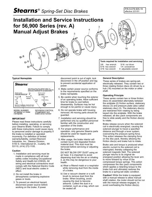
® Spring-Set Disc <strong>Brakes</strong>P/N 8-078-905-19effective 2/21/01Installation and Service Instructionsfor 56,900 Series (rev. A)<strong>Manual</strong> <strong>Adjust</strong> <strong>Brakes</strong>Tools required for installation and servicing:3/8 hex wrench 5/16 nut driver5/16 hex wrench 1/4 screwdriver3/16 hex wrench 8 adjustable wrenchTypical NameplateIMPORTANTPlease read these instructions carefullybefore installing, operating, or servicingyour Stearns Brake. Failure to <strong>com</strong>plywith these instructions could cause injuryto personnel and/or damage to property ifthe brake is installed or operatedincorrectly. For definition of limitedwarranty/liability, contact RexnordIndustries, Inc., Stearns Division,5150 S. International Dr., Cudahy, WI53110, (414) 272-1100.Caution1. Installation and servicing must bemade in <strong>com</strong>pliance with all localsafety codes including OccupationalSafety and Health Act (OSHA). Allwiring and electrical connections must<strong>com</strong>ply with the National Electric Code(NEC) and local electric codes ineffect.2. Do not install the brake inatmospheres containing explosivegases or dusts.3. To prevent an electrical hazard,disconnect power source beforeworking on the brake. If powerdisconnect point is out of sight, lockdisconnect in the off position and tagto prevent accidental application ofpower.4. Make certain power source conformsto the requirements specified on thebrake nameplate.5. Be careful when touching the exteriorof an operating brake. Allow sufficienttime for brake to cool beforedisassembly. Surfaces may be hotenough to be painful or cause injury.6. Do not operate brake with housingremoved. All moving parts should beguarded.7. Installation and servicing should beperformed only by qualified personnelfamiliar with the construction andoperation of the brake.8. For proper performance andoperation, only genuine Stearns partsshould be used for repairs andreplacements.9. After usage, the brake interior willcontain burnt and degraded frictionmaterial dust. This dust must beremoved before servicing or adjustingthe brake.DO NOT BLOW OFF DUST using anair hose. It is important to avoiddispersing dust into the air or inhalingit, as this may be dangerous to yourhealth.a) Wear a filtered mask or a respiratorwhile removing dust from the insideof a brake.b) Use a vacuum cleaner or a softbrush to remove dust from thebrake. When brushing, avoidcausing the dust to be<strong>com</strong>eairborne. Collect the dust in acontainer, such as a bag, which canbe sealed off.General DescriptionThese series of brakes are spring-set,electrically released. They contain two orthree rotating friction discs (4) driven by ahub (16) mounted on the motor or othershaft.Operating PrincipleThese series contain two or three frictiondiscs (4) assembled alternately betweenthe endplate (2) friction surface, stationarydisc(s) (3) and pressure plate (also calledstationary disc) (3). The stationary disc(s)are restrained from rotating by beingkeyed into the endplate. With the brakereleased, all disc pack <strong>com</strong>ponents arefree to slide axially and the friction disc(s)to rotate.Brake release occurs when the solenoidcoil is electrically energized, causing thesolenoid plunger to travel a specifieddistance and through a lever system,over<strong>com</strong>ing the pressure spring force.This action releases the clamping forceon the disc pack, thereby allowing thefriction disc(s) and brake hub to rotate.Brake sets and torque is produced whenelectric current to the solenoid coil isinterrupted, thereby collapsing thesolenoid magnetic field. The solenoidplunger returns to its original deenergizedposition allowing the lever armto move forward by virtue of the<strong>com</strong>pressed torque springs. This action<strong>com</strong>presses the disc pack <strong>com</strong>ponentswhich applies a retarding torque to thebrake hub and ultimately restores thebrake to a spring-set static condition.Caution! While the brake is equippedwith a manual release to allow manualshaft rotation, the motor should not be runwith the manual release engaged, toavoid overheating the friction disc(s).
BRAKE MOUNTING (<strong>Manual</strong> <strong>Adjust</strong>)Place hub on motor shaft.Position hub on shaft as shown.! "(Tighten set screws to motor shaft.'Remove brake housingand gasket.&Slide endplate over hub noting position of stabilizersprings, if used. (Refer to Friction Disc Replacement,View 4.)counterclockwise%Mount brake endplate to motor C-face.$Connect coil leadwires to power supply. Refer tonameplate for voltage rating.*Caution: Keep wiring away from pinch points andmoving <strong>com</strong>ponents.#* For vertical assembly of 20 & 25 lb-ftbrakes refer to page 5.Replace brake housingand tighten to 8 in-lb.*For DC voltagessee sheet8-078-950-00.clockwise2
!To increase air gap, turn adjustingscrew (10) counterclockwise.AIR GAP ADJUSTMENTSeries 56,900As friction disc wear the air gap will increase. When plunger gets to the reset position, the air gap must be adjusted.Air Gap Settings*tTorque(lb-ft) 56,X00 Series1.5, 3 & 6 .385 – .03010 & 15 .450 – .03020 & 25 .500 – .030*For reference only"To decrease air gap, turn adjustingscrew (10) clockwise.clockwise!Remove brake housing.FRICTION DISC REPLACEMENTSeries 56,900"Remove support plate screws andlift support from brake.counterclockwisecounterclockwisecounterclockwise(Remove and discard oldfriction disc.'Install new friction disc(s) andstationary disc(s) as shown.&Reposition support plate on endplateand tighten mounting screws to 55 in-lb.Reposition housing and% tighten nuts to 8 in-lbs.*For brakes with vertical springs see page 5.clockwiseclockwise3
!Remove brake housing.COIL REPLACEMENTSeries 56,900"Disconnect coil leadwiresfrom power source.counterclockwise(Insert screwdriver between supportplate and lever arm and pry forward.'Lift plunger/solenoid lever assemblyout of coil.&Remove plunger guide.%Discard coil.$A) Insert new coil. (Lead wires insame position as old coil.)B) Insert plunger guide.#A) Reinsert plunger into coil; drop pivotpin into cradle of support plate.B) Remove screwdriver.BAReconnect coil leadwires to power source.) *Reassemble housing. Tighten to 8 in-lbs.clockwise4
Vertical Brake AssemblyDouble disc brakes (10 & 15 lb-ft.) universalmount but require separator springs whichare preassembled to the stationary disc.These discs are inserted spring first into thebrake. Refer to figure 5A below.Figure 5AInstallation Procedure for 20 and25 lb-ft brakes if mounted verticalto motor shaft (These brakes are factoryassembled for horizontal operation.)Remove support plate by loosening thethree mounting screws.Remove stationary discs and friction discs.Using the spring kit provided with this brake,insert three springs of identical color intoeach stationary disc hole. Springs areinserted from the side opposite the indentmark (see Figure 5B). Stationary disc shouldbe placed on a clean flat surface with aclearance hole to allow the tip of the springto extend through the bottom side of thesupport plate. Using the 1/8 pin providedand a hammer, drive the hold until the largecoil diameter bottoms out against the disc.Figure 5BReassemble the disc pack with thestationary discs in the proper arrangementshown in Figure 5C.Mount support plate and torque screwsevenly to 55 in-lbs.Figure 5CTorque <strong>Adjust</strong>mentBrake is factory set for nominal rated statictorque which is maximum torque. Torquemay be decreased up to 50% for increasedstopping times up to 2 second stop time.Turn both adjustment nuts (11N), Figure 6,equal amounts counterclockwise todecrease torque. See Table A for torquereduction permissible amounts.Figure 6TABLE ANominal Original Maximum % TorqueStatic Spring Counter- ReductionTorque Height clockwise per(lb-ft) (inches) Turns Turn10 1-9/1615 1-9/1620 1-9/165-1/2 9%25 1-1/2General MaintenanceWarning! Any mechanism or load held inposition by the brake should be secured toprevent possible injury to personnel ordamage to equipment before anydisassembly of the brake is attempted orbefore the manual release knob is operatedon the brake.Observe all cautions listed at the beginningof this manual before attempting to servicebrake.TroubleshootingA. If brake does not stop properly oroverheats, check the following:1. Are friction discs excessively worn,charred, or broken?2. Hub may have be<strong>com</strong>e loose andshifted on shaft. Recheck set screwtorque. Reposition hub if shifted.3. With brake de-energized and housing(7) removed, check <strong>com</strong>pressed lengthof pressure springs (11). Compare toTable A values and adjust to minimumheight to obtain desired stop times.4. Is solenoid air gap adjusted correctly?See Page 3 for instructions.5. Solenoid may not be energizing andreleasing the brake. Check voltage atthe coil and <strong>com</strong>pare to the coil and/ornameplate voltage rating.6. Check linkage for binding. Depresssolenoid plunger down to frame surface.Movement to be without binding.7. Brake coil should be energized at sametime or prior to energization of motor,and de-energized at same time or afterde-energization of motor.8. Replace friction disc(s) when worn areais one half of original thickness.9. Check to be sure wear adjust screwsare of equal height. Measure frominboard side of support plate with depthmicrometer. Turn one screw to obtainequal height.B. If solenoid hums, pulls in slowly, orcoil burns out, check the following:1. Solenoid plunger to frame contact surfacemay be excessively dented.2. Are solenoid plunger to frame contactsurfaces sticky and dirty.3. Solenoid mounting screws may havebe<strong>com</strong>e loose, causing frame to shift andplunger to seat improperly.5
Information required when orderingreplacement parts:Give Part Number of parts or kits needed, BrakeModel Number, and Brake Serial Number. TheBrake Model and Serial Number may identifyspecial brakes not covered by this parts list.When ordering hubs, specify shaft diameter(hub bore) and keyway.Enclosure is specified as follows:NEMA 4X (formerly referred to as BISSC washdown)Torque (lb-ft)101520 & 25CurrentACDCACDCACDCNEMA Enclosure4X4X4X4X4X4XTABLE 1Components of Standard AC or DC BrakeItemDescriptionBrake ModelNumber →Part Number ↓1-056-934-001-056-938-001-056-944-001-056-948-001-056-954-00 & 964-001-056-958-00 & 968-00A1AGasket NEMA 4 (close coupled only)Hardware Kit - NEMA 4X8-122-503-005-66-1018-00X1X1X1X1X1X17Housing & Release Assembly - NEMA 4X5-07-5045-0011 1 1 1133A3BStationary disc kit (3 disc horizontal)Stationary disc kit (2 disc universal)Stationary disc kit (3 disc vertical)5-66-8354-005-66-8355-005-66-8356-0011113131NotshownVertical spring kit (3 disc)5-63-0525-001 1144SDP162Friction disc kitStabilizing springDisc pack kit - 2 discDisc pack kit - 3 discHub and setscrew assy.(2 & 3 disc)Endplate Assy.5/8 bore7/8 bore1-1/8 bore2 & 3 disc2 & 3 disc (NEMA 4X)5-66-8462-005-66-8356-005-66-8602-005-66-8603-005-16-5153-00-01B5-16-5153-00-01D5-16-5153-00-01E8-002-582-22-30F5-02-5048-002*1111X12*1111X12*1111X12*1111X13*1111X13*1111X1*Certain multiple friction disc modelnumbers require a single stabilizer clip(4S) added to each friction disc. If yourbrake has these clips, they must bereplaced when the friction disc isreplaced. This clip is included aspart of the friction disc kit 5-66-8462-00.X - Model numbers with the number 8 inthe 8th position indicate close coupledbrakes.6
SupportPlateAssemblySolenoid andCoil AssemblyTorque (lb-ft)NEMA Enclosure104X15& 204X254XTABLE 2Components of Support Plateand Coil AssemblyItem688WP11N101111S172629A126131142SAC <strong>Brakes</strong>Z12A115/230 Vac230/460 Vac115 Vac230 Vac460 Vac575 Vac115/230 Vac230/460 Vac115 Vac230 Vac460 Vac575 Vac115/230 Vac230/460 Vac115 Vac230 Vac460 Vac575 VacBrake release interlock switchCC(optional)DC <strong>Brakes</strong>12B157DescriptionBearingSolenoid leverRetaining ringSpacerTorque adjustment nutWear adjustment screwPressure springPressure springSpring washerLever arm and stop nut assemblyBearing pinPlunger stopSupport plate and spring studassembly (3 housing studs)Pivot pinMounting screwsNo. 4 Solenoid kitNo. K4coil kit60 HzNo. K4+coil kit60 HzNo. M4+coil kit60 HzNo. K4 + coilassemblyNo. M4 + coilassemblyNo. P4 + coilassemblyElectronic DCswitch kit115 Vdc230 Vdc115 Vdc230 Vdc115 Vdc230 Vdc24/28 Vdc115 Vdc230 VdcSupport PlateAssembly. (ItemsM through Yand EA )→Part Number ↓8-006-501-008-008-504-019-03-0057-009-45-0168-009-40-3928-008-100-507-009-70-1523-009-70-1524-009-46-0010-005-17-5011-009-29-4826-008-094-503-005-26-5020-009-29-4836-009-25-9013-005-66-5047-005-66-6457-335-66-6459-335-66-6451-335-66-6452-335-66-6454-335-66-6455-335-66-6407-235-66-6409-235-66-6401-235-66-6402-235-66-6404-235-66-6405-235-66-6457-235-66-6459-235-66-6451-235-66-6452-235-66-6454-235-66-6455-235-57-5526-005-96-6416-235-96-6417-235-96-6466-235-96-6467-235-96-6446-235-96-6447-235-57-5712-155-57-5716-155-57-5717-155-42-5564-0011122224111113111111111111125-42-5566-001112224111113111111111111125-42-5566-0011122241111131111111111111TABLE 3Contents of Kits and AssembliesItemA33A4DP16Z12A12B157CCKit DescriptionHardware kit NEMA 4X (5-66-1018-00)1 Endplate oil seal1 Drain plug3 Housing nuts3 Housing nut seal washers2 Endplate conduit pipe plugs1 Housing-to-endplate gasketStationary disc kit (5-66-8354-00)1 Stationary discStationary disc kit (5-66-8355-00)2 Stationary discs with springsFriction disc kit (5-66-8462-00)1 Friction disc2 Stabilizing springs(for 1-1/2-6 lb-ft brake use only)Disc pack kit (5-66-860X-00)1, 2 or 3 Friction disc(s)1, 2 or 3 Stationary disc(s)2 Stabilizing springs(for 1-1/2-6 lb-ft brake use only)3, 6 or 9 Stationary disc separator springsHub and set screw assembly all types,all bores (5-16-5153-00)1 Brake hub2 Set screwsNo. 4 solenoid kit (5-66-5047-00)1 Plunger1 Solenoid link1 Frame1 Solenoid link cap screw1 Solenoid link nut3 Solenoid mounting screwsNo. 4 AC coil kit (5-66-64XX-X3 and DC coilassembly (5-96-64XX-X3)Coil / Top Plunger guide / Wire nutDC switch kit (5-57-571X-15)1 Electronic switch1 Mounting bracket3 Bracket mounting screws4 Switch mounting screws4 Nuts4 Lock washers5 Crimp connectorsBrake release interlock switch (5-57-5526-00)1 Microswitch1 Mounting bracket2 Bracket mounting screws2 Switch mounting screws2 Lock washer2 Nuts2 Lead wire assembly7
Rexnord Industries, Inc.Stearns Division5150 S. International Dr.Cudahy, Wisconsin 53110(414) 272-1100 Fax: (414) 277-4364Copyright© 2001 by Rexnord Industries, Inc.