Manual HOBO U26-001 - Synotech Datenlogger
Manual HOBO U26-001 - Synotech Datenlogger
Manual HOBO U26-001 - Synotech Datenlogger
- No tags were found...

You also want an ePaper? Increase the reach of your titles
YUMPU automatically turns print PDFs into web optimized ePapers that Google loves.
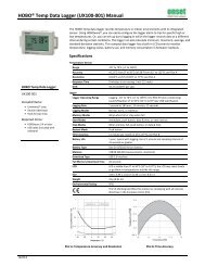
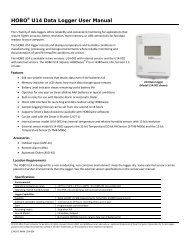
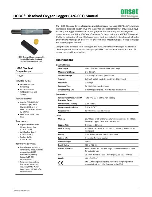
<strong>HOBO</strong>® Dissolved Oxygen Logger (<strong>U26</strong>-<strong>001</strong>) <strong>Manual</strong>The <strong>HOBO</strong> Dissolved Oxygen logger is a standalone logger that uses RDO® Basic Technologyto measure dissolved oxygen (DO). The logger has an optical sensor that provides 0.2 mg/Laccuracy. The logger also features an easily replaceable sensor cap and an integratedtemperature sensor. Using <strong>HOBO</strong>ware® software for logger setup and a <strong>HOBO</strong> WaterproofShuttle for quick data offload, this logger is easy to deploy in both freshwater and saltwaterenvironments making it an ideal tool for environmental impact studies as well as ecologicaland oceanographic research.Using the data offloaded from the logger, the <strong>HOBO</strong>ware Dissolved Oxygen Assistant cancalculate percent saturation and salinity-adjusted DO concentration as well as correct formeasurement drift from fouling.<strong>HOBO</strong> Dissolved Oxygen Logger withIncluded Calibration Boot andSponge (Shown Wet in Photo)<strong>HOBO</strong> DissolvedOxygen Logger<strong>U26</strong>-<strong>001</strong>Included Items:• Dissolved OxygenSensor Cap• Protective Guard• Calibration Boot andSpongeRequired Items:• Coupler (COUPLER-2-C)with USB Optic BaseStation (BASE-U-4) or<strong>HOBO</strong> Waterproof Shuttle(U-DTW-1)• <strong>HOBO</strong>ware Pro 3.3.1 orlaterAccessories:• Replacement DissolvedOxygen Sensor Cap(<strong>U26</strong>-RDOB-1)• Anti-Fouling Guard(<strong>U26</strong>-GUARD-2)• Sodium Sulfite(<strong>U26</strong>-CAL-SOL)You May Also Need:• For saltwater, salinity orconductivity measurementsare required; <strong>HOBO</strong>Conductivity/SalinityLogger (U24-002)recommended• For percent saturation,barometric pressure isrequired; <strong>HOBO</strong> WaterLevel Logger (U20-<strong>001</strong>-0x)recommendedSpecificationsDissolved OxygenSensor TypeMeasurement RangeCalibrated RangeAccuracyResolutionResponse TimeDO Sensor Cap LifeTemperatureTemperature Measurement/Operating RangeTemperature AccuracyTemperature ResolutionResponse TimeLoggerMemoryLogging RateTime AccuracyBatteryBattery LifeDownload TypeDepth RatingWetted MaterialsSizeWeightOptical (dynamic luminescence quenching)0 to 30 mg/L0 to 20 mg/L; 0 to 35°C (32 to 95°F)0.2 mg/L up to 8 mg/L; 0.5 mg/L from 8 to 20 mg/L0.02 mg/LTo 90% in less than 2 minutes6 months (cap expires 7 months after initialization)-5 to 40°C (23 to 104°F), non-freezing0.2°C (0.36°F)0.02°C (0.04°F)To 90% in less than 30 minutes21,700 sets of DO and temperature measurements (64 KB totalmemory); logging stops when memory fills1 minute to 18 hours±1 minute per month at 0 to 50°C (32 to 122°F) (see Plot A onnext page)3.6 V lithium battery; factory replaceable3 years (at 5 minute logging)Optical100 m (328 ft)Black Delrin®, PVC, EPDM o-rings, silicon bronze screws; ratedfor saltwater use39.6 mm diameter x 266.7 mm length (1.56 x 10.5 inches)464 g (16.37 oz)The CE Marking identifies this product as complying with allrelevant directives in the European Union (EU).15603-B MAN-<strong>U26</strong>x
<strong>HOBO</strong> Dissolved Oxygen Logger (<strong>U26</strong>-<strong>001</strong>) <strong>Manual</strong>Specifications (continued)Plot A: Time AccuracyLogger Components and OperationTemperature Sensor(Inside Logger Housing)Protective GuardCommunications Cap/LanyardDO SensorAlignment Notchfor CouplerCommunications Cap/Lanyard. This removable cap protectsthe optical communications window. An LED in thecommunications window of the logger confirms loggeroperation. When the logger is logging, the LED blinks onceevery four seconds. The LED also blinks when the logger isrecording a sample. When the logger is awaiting a start becauseit is configured to start “At Interval,” “On Date/Time,” or “UsingCoupler,” the LED blinks once every eight seconds until loggingbegins. See Connecting the Logger to a Computer orWaterproof Shuttle for details on using the communicationswindow.Mounting Hole. Use the hole on the communications cap tomount the logger. See Deploying the Logger for moreinformation.Alignment Notch for Coupler. Use this notch to align thecoupler when communicating with the logger. See Connectingthe Logger to a Computer or Waterproof Shuttle for moreinformation.DO Sensor. This optical sensor measures dissolved oxygen usingRDO® Basic Technology. It is shipped with a red dust cap thatmust be replaced with a green sensor cap that lasts for sixmonths plus a one-month grace period. See Installing theSensor Cap for more details.Protective Guard. This removable guard protects the DOsensor. Unscrew it to install or replace the sensor cap asneeded. See Installing the Sensor Cap for more details.Temperature Sensor. This built-in sensor (not visible indiagram) measures temperature.MountingHoleWARNING: This logger can be damaged by mechanicalshock. Always handle the logger with care. The logger may bedamaged if it is dropped. Use proper packaging whentransporting or shipping the logger.Do not attempt to open the logger case or sensor housing.Disassembling of the logger case or sensor housing will causeserious damage to the sensor and logger electronics. There areno user-serviceable parts inside the case. Contact OnsetTechnical Support at 1-800-LOGGERS (1-800-564-4377) or anauthorized Onset dealer if your logger requires servicing.Installing the Sensor CapThe logger ships with a replaceable sensor cap that provides sixmonths of continuous use. Once the cap is initialized, aninternal clock within the logger will count down until the sensorcap expiration date. When the sensor cap expires, you will needto replace it with a new cap (<strong>U26</strong>-RDOB-1). The sensor cap isintended for six months of actual deployment, but theexpiration date is seven months from the date the cap wasinitialized. This allows for any time needed between launchingthe logger and physically deploying as well as extra time in caseyou are not able to get the logger after exactly six months ofdeployment. To install the sensor cap:1. Unscrew the protective guard covering the DO sensor (seediagram at left).2. Remove the red dust cap that protects the sensor duringshipping.3. Take the green sensor cap out of the canister.4. With the flat part of the DO sensor pointing down and thethe green sensor cap oriented with the arrow up, slide thesensor cap over the sensor until it snaps in place. The capshould be snug against the logger housing without any gaps.Sensor cap with arrowpositioned up; slide over DOsensor until it snaps in placeDO sensor, flatside down5. Screw the external protective guard back on until tight.Important: The sensor cap expires 7 months (to the day) after ithas been initialized. The logger will record a value of -888 mg/Lat each logging interval after the cap has expired. Initializationoccurs automatically when the cap is installed while the loggeris logging. You can also initialize it from the Status window in<strong>HOBO</strong>ware or when using the Lab Calibration tool. To see whenthe sensor cap expires after being initialized, check the Status in<strong>HOBO</strong>ware for the expiration date. The cap also has a shelf life;check the “Install By” date printed on the canister.1-800-LOGGERS 2 www.onsetcomp.com
<strong>HOBO</strong> Dissolved Oxygen Logger (<strong>U26</strong>-<strong>001</strong>) <strong>Manual</strong>Connecting the Logger to a Computer orWaterproof ShuttleTo connect the logger to a computer, use either the Optic USBBase Station (BASE-U-4) or <strong>HOBO</strong> Waterproof Shuttle (U-DTW-1) with a coupler (COUPLER2-C). To launch and read out thelogger in the field, use one of these three methods:• Laptop computer with Optic USB Base Station (BASE-U-4)and coupler (COUPLER2-C)• <strong>HOBO</strong> Waterproof Shuttle (U-DTW-1, Firmware Version3.2.0 or later) and coupler (COUPLER2-C)• <strong>HOBO</strong> U-Shuttle (U-DT-1, Firmware Version 1.16 or later)with Optic USB Base Station and coupler (COUPLER2-C)IMPORTANT: USB 2.0 specifications do not guaranteeoperation outside the range of 0°C (32°F) to 50°C (122°F).1. Follow the instructions that came with your base station orWaterproof Shuttle to attach it to a USB port on thecomputer.2. Unscrew the pointed cap on the communications end of thelogger.3. Attach the coupler to the base station or shuttle.4. Insert the logger into the coupler, aligning the bump/arrowon the coupler with the notches on the logger. Be sure thatit is properly seated in the coupler. If the logger has neverbeen connected to the computer before, it may take a fewseconds for the new hardware to be detected by thecomputer. Note: If you are using the <strong>HOBO</strong> WaterproofShuttle as a base station with a computer, briefly press thecoupler lever to put the shuttle into base station mode. Agreen LED on the shuttle or base station indicates goodcommunication.Notches in logger; use toalign with bump in couplerBump on couplerCommunications end of loggerTo base stationor shuttleCoupler lever5. After logger communications are complete, remove thelogger from the coupler. Make sure the o-ring is still in thegroove inside the cap and then reinstall thecommunications cap.IMPORTANT: When connected to a coupler, the logger is“awake” and consumes significantly more power than when itis disconnected and considered “asleep.” The logger willautomatically “go to sleep” after being left in the coupler for 30minutes. It will no longer appear as a USB device connected tothe computer. If this occurs, remove it from the coupler andstart the instructions to connect the logger to a computer orwaterproof shuttle over again.Calibrating the Logger with the LabCalibration ToolUse the Lab Calibration tool in <strong>HOBO</strong>ware when you need tocalibrate the logger before deploying it or after replacing anexpired sensor cap. The tool sets the gain and offsetadjustment values for the logger by:• Restoring logger calibration values to the factorydefaults,• Using your own gain and offset adjustment values, or• Calculating the values with a three-step calibrationprocedure.In the three-step procedure, the logger is first calibrated to100% saturation by placing it in water-saturated air. Then, youcan calibrate the logger to 0% saturation by placing it in sodiumsulfite or another 0% oxygen environment (recommended if thelogger will be deployed in water with DO levels of 4 mg/L or less).IMPORTANT: Lab calibration only affects future launches; anydata saved in the logger will be based on the previouscalibration values. If the sensor cap is installed and it has notyet been initialized, you will be prompted to do so. Follow theinstructions on the screen.To complete these steps, you will need fresh water, thecalibration boot and sponge supplied with the logger, and asource for current barometric pressure at your current location.You will also need sodium sulfite solution and a 7.6 cm (3 inch)beaker if you will be calibrating to 0% saturation.The fresh water, logger, and sodium sulfite (if applicable) shouldbe left out in the lab where the calibration is being done longenough so that they are at room temperature. If the logger wasdeployed previously, make sure the sensor is clean and dry (seeMaintenance for more details). To use the Lab Calibration tool:1. Connect the logger to the computer as described in theprevious section. Stop the logger if it is currently logging orawaiting a coupler or delayed start.2. From the Device menu, click Lab Calibration.3. The current gain and offset adjustments are displayed inthe top pane of the Lab Calibration window along with thedate and time the last lab calibration was completed (ifapplicable). Completing Steps 1 through 3 in the LabCalibration tool will result in new gain and offsetadjustment values based on the current logger conditions.Continue to the next section for details on how to completethese steps.If you already know what the gain and offset values shouldbe (for example, the values from a previous calibration thatyou want to use again) or want to return to the defaultfactory values, click the “I know my values, skip to Finish”button. This will automatically move you to “Step 3: Finish”in the Lab Calibration window. Either click the “Reset toFactory Defaults” button or type in the desired gainadjustment and offset adjustment values and click the“Send Calibration to the Logger” button. Note: If you decideyou do not need to change the calibration, click Close tocancel the calibration and revert back to the last savedlogger values.1-800-LOGGERS 3 www.onsetcomp.com
<strong>HOBO</strong> Dissolved Oxygen Logger (<strong>U26</strong>-<strong>001</strong>) <strong>Manual</strong>• Make sure the logger is fully submerged and not in directsunlight to minimize temperature changes that areunrelated to water temperature.• When deploying the logger in rivers, streams, and ponds,insert the logger in a PVC or ABS pipe for protection fromdebris (if possible). The pipe should have enough holes toensure good circulation of water to the sensor.• If possible, position the logger so the sensor face isoriented vertically. After deploying in the water, movethe logger around slightly to eliminate any bubbles thatmay have formed.• Do not deploy the logger in freezing water with moving icewhere the logger could be crushed.• Use the optional anti-fouling guard to protect againstfouling. Unscrew the protective guard and replace it withthe anti-fouling guard.• If fouling is expected during deployment, use fieldcalibration readings from both the beginning and end ofthe deployment as described in the next section. Thesereadings can then be entered into the <strong>HOBO</strong>wareDissolved Oxygen Assistant to compensate for anymeasurement drift due to fouling. Scrub fouling off thelogger with a plastic bristle brush.• When deploying the logger in saltwater, you will need aconductivity value to enter in the Dissolved OxygenAssistant that adjusts the data from the logger forsalinity. If the salinity is constant through thedeployment, you will need a single salinity reading fromeither a conductivity meter or salinometer. However, ifthe conductivity changes, then you will need a data filewith salinity or specific conductivity readings for theentire deployment. Consider deploying a <strong>HOBO</strong>Conductivity logger (U24-002) next to this DO logger touse the resulting data file for salinity data.• To generate a percent saturation series, you will need todeploy a barometric pressure logger (such as a <strong>HOBO</strong>Water Level Logger, U20-<strong>001</strong>-0x) or have access to anearby weather station to gather barometric pressuredata. This data is necessary for the Dissolved OxygenAssistant to calculate percent saturation.Taking Field Calibration ReadingsIf fouling is expected during the deployment, you can takecalibration readings at the beginning and end of thedeployment to enter in the Dissolved Oxygen Assistant. This willadjust the data from the logger to compensate for anymeasurement drift due to fouling. There are two methods fortaking field calibration readings: the first method involvestaking readings using a dissolved oxygen meter or titrationwhile the second method involves calibrating the logger in100% water-saturated air. The first method is recommendedbecause it is quicker to get the necessary calibration readings;the second method can take 40 minutes or more to achieveequilibrium with temperature extremes.To Take Calibration Readings Using a DO Meter or Titration:1. The logger must be logging. Take a DO measurement of thewater where the logger is being deployed using either a DOmeter or by titration. If using a meter, make sure it iscalibrated and allow time for the meter probe to stabilize(this will occur when three meter measurements taken in arow are within your accuracy tolerance).If the logger is being deployed in saltwater, adjust themeter measurements for salinity using a meter with bothconductivity and DO probes. If the saltwater has a constantsalinity, you can use a DO meter where you can enter thatsalinity value to adjust the readings. If the salinity and/orDO are changing rapidly, then you will need to get a sampleof the water in a container large enough for both the loggerand meter probe to be completely submerged. Place bothdevices in the water long enough for them to stabilize andthen for the DO logger to log at least two values, and take aconcurrent meter reading.2. Record the reading, date, and time of the measurement in afield notebook.3. At the end of the deployment, repeat steps 1 and 2.To Take Calibration Readings Using 100% Water-Saturated Air:1. The logger must be logging. You will need fresh water, theincluded calibration boot and sponge, and the currentbarometric pressure from a <strong>HOBO</strong> U20 Water Level logger,a barometer, or a nearby weather station.2. If the logger has been in salt water, clean the logger bodyand sensor cap as described in the Maintenance section.Make sure the sensor cap is dry before continuing.3. Make sure the protective guard or anti-fouling guard isinstalled on the logger.4. Wet the small sponge with fresh water. Squeeze out anyexcess water.5. Place the sponge in the end of the calibration boot.6. Insert the logger in the calibration boot so that there isapproximately a 1 cm (0.5 inch) overlap between the end ofthe boot and the body of the logger. This will ensure thereis enough space between the end of the logger and thesponge (the logger should not be pressed up tightly againstthe sponge).7. Allow at least 40 minutes for the logger to reachtemperature equilibrium, and then write down the date andtime in a field notebook.8. Write down the barometric pressure at that time (note theelevation if the barometric reading has been adjusted forsea level).9. Repeat these steps at the end of the deployment.Reading Out the Logger and RedeployingYour readout and maintenance schedule will be determined bythe amount of fouling at the site. To read out the logger in thefield:1. Take a field calibration reading as described in the TakingField Calibration Readings section.2. If the logger was in saltwater and you did not deploy a<strong>HOBO</strong> Conductivity Logger, then use a conductivity meteror salinometer to take a conductivity reading. Write downthe reading and the date and time.1-800-LOGGERS 5 www.onsetcomp.com
<strong>HOBO</strong> Dissolved Oxygen Logger (<strong>U26</strong>-<strong>001</strong>) <strong>Manual</strong>3. Remove the logger from the water and read out the datafrom the logger using a shuttle or computer with a basestation.4. If you are deploying it again, clean the sensor (seeMaintenance for details).5. Check the expiration date for your cap and make sure it willnot expire before the end of your deployment. Replace it ifneeded.6. Relaunch the logger if it is not already logging.7. Take another field calibration reading after the logger iscleaned.8. Redeploy the logger.Using the <strong>HOBO</strong>ware DissolvedOxygen AssistantUse the Dissolved Oxygen Assistant to obtain accurateDissolved Oxygen readings if the logger was deployed in asaltwater environment or if percent saturation is required. Alsouse this assistant if you took field calibration readings. TheDissolved Oxygen Assistant is only available in <strong>HOBO</strong>ware fromthe Plot Setup window when you open a file from this logger.To use the assistant:1. Offload the most recent data files from the shuttle or loggerto your computer.2. Open a data file in <strong>HOBO</strong>ware.3. In the Plot Setup window, select the Dissolved OxygenAssistant and click Process.4. In the Dissolved Oxygen Assistant window, enter thesalinity, barometric pressure, and field calibrationinformation as needed. Click the Help button in theDissolved Oxygen Assistant for more details and to learnabout the ranges of input data allowed.5. Plot the data and save it as a project file.MaintenanceTo clean the sensor cap:1. Remove the protective guard or anti-fouling guard, butleave the sensor cap on the sensor.2. Rinse the logger with clean water from a squirt bottle orspray bottle.3. Gently wipe the cap with a soft-bristled brush (such as atoothbrush) or soft cloth if biofouling is present. UseAlconox® to remove grease.4. If extensive debris or mineral build-up is present, soak thecap end in vinegar for 15 minutes, then soak it in deionized(DI) water for another 15 minutes.5. If the logger is being immediately redeployed with the samesensor cap, a field calibration is adequate. If a new sensorcap is being installed, a lab calibration with <strong>HOBO</strong>ware isrecommended. When storing the logger betweendeployments, keep it in the calibration boot (wet the smallsponge with fresh water, place the sponge in the end of thecalibration boot, and then insert the logger in the boot.)WARNING: Do not use organic solvents; they will damagethe sensor. Do not remove the sensor cap from the sensor priorto cleaning with a brush. Only clean the sensor when youreplace the sensor cap. See the full instructions that ship withthe replacement sensor cap. Do not wet the sensor optical lensarea with water or any solution. Remove the cap and gentlywipe the window with a soft cloth.To clean the logger body:1. Make sure the sensor cap is installed on the logger.2. Gently scrub the logger body with a plastic bristle brush ornylon dish scrubber.3. Use Alconox® to remove grease.4. Soak in vinegar to remove mineral deposits.5. Rinse the logger with deionized (DI) water.Battery GuidelinesThe battery life of the logger should be three years or more.Actual battery life is a function of the number of deployments,logging interval, and operation/storage temperature of thelogger. Frequent deployments with fast logging intervals,continuous storage/operation at temperatures above 35°C(95°), and keeping the logger connected to the coupler willresult in significantly lower battery life. For example, thebattery may last less than a year with a 1-minute logginginterval. To obtain a three-year battery life, a logging interval offive minutes or greater should be used and the logger should beoperated and stored at temperatures between 0° and 25°C (32°and 77°F).The logger can report and log its battery voltage. If the batteryfalls below 3.2 V, the logger will record a “bad battery” event inthe datafile. The logger will record a second “bad battery”event and stop logging when the battery falls below 3.1 V. If thedatafile contains “bad battery” events, the logger should bereturned to Onset for battery replacement. Note the loggerdoes not have to be recording the battery channel for it todetect bad battery events. The logger will record these eventsregardless of what channels are logged. To have your logger’sbattery replaced, contact Onset or your place of purchase forreturn arrangements. Do not attempt to replace the batteryyourself. Severe damage to the logger will result if the case isopened without special tools, and the warranty will be voided.WARNING: Do not cut open, incinerate, heat above 100°C(212°F), or recharge the lithium battery. The battery mayexplode if the logger is exposed to extreme heat or conditionsthat could damage or destroy the battery case. Do not disposeof the logger or battery in fire. Do not expose the contents ofthe battery to water. Dispose of the battery according to localregulations for lithium batteries.1-800-LOGGERS (564-4377) • 508-759-9500www.onsetcomp.com • loggerhelp@onsetcomp.com© 2012 Onset Computer Corporation. All rights reserved. Onset, <strong>HOBO</strong>, and <strong>HOBO</strong>ware aretrademarks or registered trademarks of Onset Computer Corporation. RDO is a registeredtrademark of In-Situ® Inc., Fort Collins, CO USA. All other trademarks are the property of theirrespective companies.15603-B MAN-<strong>U26</strong>x