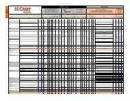
Installation Sheet - CURT Manufacturing
Installation Sheet - CURT Manufacturing
Installation Sheet - CURT Manufacturing

Create successful ePaper yourself
Turn your PDF publications into a flip-book with our unique Google optimized e-Paper software.
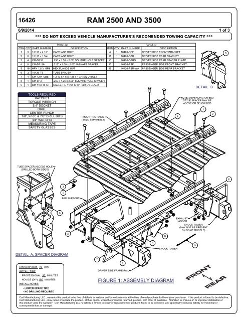
16426 RAM 2500 AND 35006/9/20141 of 3*** DO NOT EXCEED VEHICLE MANUFACTURER'S RECOMENDED TOWING CAPACITY ***ITEM QTY PART NUMBERParts ListDESCRIPTIONITEM QTY PART NUMBERParts ListDESCRIPTION1 3 1/2-13 x 4 1/2 CARRIAGE BOLT2 8 1/2-13 x 1 3/4 CARRIAGE BOLTA 1 16426-DSF DRIVER SIDE FRONT BRACKETB 1 16426-DSR DRIVER SIDE REAR BRACKETD3 4 CM-SP33 .250 x 1.50 x 2.00" SQUARE HOLE SPACERC 1 16426-DSRS DRIVER SIDE REAR SPACER PLATE4 8 CM-SP136 .313" x 1.00 x 2.00" U-SHAPE SPACERD 1 16426-PSF PASSENGER SIDE FRONT BRACKET5 19 HFN 1213, GR8 HEX FLANGE NUTE 1 16426-PSR-WA PASSENGER SIDE REAR BRACKET6 2 16426-TS TUBE SPACER7 4 CM-1214-UBS 1/2-13 x 4.5 x 7.25 x 1 3/4 SQ U-BOLT8 1 CM-SP3 .250 x 1.25 x 2.00" SQUARE HOLE SPACER9 1 CM-116415-CT CABLE TIE 11/64 X 15" 50# UV BLACKDETAIL BTOOLS REQUIREDRATCHETTORQUE WRENCH3/4" SOCKETDRILLCENTER PUNCH1/8", 9/16", & 7/8" DRILL BITS3/4" WRENCHMEASURING TAPESAFETY GLASSESMOUNTING RAILS(SOLD SEPARETLY)4NOTE: DEPENDING ON BEDSTYLE SPACER MAY BEABOVE OR BELOW BED12TUBE SPACER ACCESS HOLE(DRILLED BOTH SIDES)E35BED SUPPORT6ABEXHAUSTHANGERSHOCK TOWER(MAY NOT BE PRESENTON SOME MODELS)CSHOCK TOWER9DETAIL A: SPACER DIAGRAMHITCH WEIGHT: 24 LBS.INSTALL TIMEPROFESSIONAL: 90 MINUTESNOVICE (DIY): 180 MINUTESINSTALL NOTES:78DRIVER SIDE FRAME RAILFIGURE 1: ASSEMBLY DIAGRAM- LOWER SPARE TIRE- NO DRILLING REQUIREDCurt <strong>Manufacturing</strong> LLC., warrants this product to be free of defects in material and/or workmanship at the time of retail purchase by the original purchaser. If the product is found to be defective,Curt <strong>Manufacturing</strong> LLC., may repair or replace the product, at their option, when the product is returned, prepaid, with proof of purchase. Alteration to, misuse of, or improper installation ofthis product voids the warranty. Curt <strong>Manufacturing</strong> LLC.'s liability is limited to repair or replacement of products found to be defective, and specifically excludes liability for incidental orconsequential loss or damage.
16426WARNING:- Do not install mounting rails over plastic bed liners. Plastic liners must be trimmed for metal to metal contact.(Mounting rails may be installed on spray on liner.)- Use only supplied fasteners for installation.- Before installing mounting rails and hitch, measure to be sure there will be enough clearance between the truck and trailer to allow for turns.<strong>Installation</strong> Instructions:1. Lower and remove the spare tire.RAM 2500 AND 35002. Place the rear mounting rail in the box of the truck. Using a tape measure center the rail between the box sides. Position the rail at theproper distance from the rear edge of the truck box as shown in Figure 2. Note: Rail must be perpendicular to the length of the truck bed.2 of 3WARNING: When drilling holes be aware of potential risks to vehicle components and make appropriate safe guards to protectthem from damage.3a. Mark and center punch the bolt positions, as shown in Figure 2. Move rail out of the way, drill (2) 1/8" holes in Row 1. Hold the (B)driver side rear bracket and (C) driver side rear spacer plate in position and verify they align with the hole in the bed and the hole in theshock tower, as shown in Figure 1. Note: If the wire harness interferes with the bracket, detach it from the inside of the driver sideframe between the fuel tank and the shock tower. Hold the (E) passenger side rear bracket in position and verify it aligns with the holein the bed and if present the shock tower hole, as shown in Figure 1. Note: If needed, lower the exhaust and heat shield to gain accessto the passenger side frame.3b. Reposition rear rail in place and measure 22" on center from rear to front rails. Drill 1/8" hole in Row 3. Check location of front holes inrelation to the bed support to be sure there is space for the front brackets and fasteners to be secured. This process is to verify that thehole locations are correct due to bed support location variances.3c. If an interference issue exists with the front bed support, it will be necessary to slightly shift the location of the holes and bracketstowards the rear of the vehicle. Shift the (B & E) rear brackets toward the rear of the vehicle while checking that the supplied hardwarewill still pass through the bracket and the existing hole in the shock tower (if present). Mark and drill new hole locations through rearframe brackets. Verify bed support clearance similar to Step 3b. Repeat this entire process as necessary. If the vehicle does not havethe passenger shock tower similar to the driver side, The supplied U-bolt will pass through the slot in the mounting bracket.4. Temporarily position the rear frame brackets on the frame and check that the 1/8" drilled holes align with the slots in the brackets. Oncein position center punch and drill the rest of the holes in Rows 1 and 2, as shown in Figure 2. Remove the frame brackets from thevehicle.5. Enlarge the 1/8" holes to 9/16" in Rows 1 and 2.6. From under the vehicle, enlarge the holes in the rear bed support to 7/8". This will allow the tube spacers to pass through.Note: Do not enlarge the holes in the bed.7. Reposition the rear mounting rail over the holes enlarged in Step 5.8. Install the 1/2" x 1-3/4" carriage bolts with the u-shaped spacers in the rear holes of the rear rail (Row 1). Place the u-shaped spacersbetween the bracket and the bed to prevent the bed from collapsing when the bolts are tightened. Install the 1/2" x 4-1/2" carriage boltsin the front holes of the rear rail (Row 2).Note: Depending on bed style, place spacers above or below bed.9. On the rear driver side, slide the tube spacer up through the bed support, around the carriage bolt as shown in Detail A. While holdingthe tube spacers in position, Place the (B) driver side rear bracket and (C) driver side rear spacer plate on the inside of the frame, asshown in Figure 1. Install a U-bolt to hold the plate in position. The U-bolt wraps around the outside of the frame, right behind the rearbed support. Loosely install 1/2" flange nuts onto the ends of the bolts.10. On the rear passenger side, slide the tube spacer up through the bed support, around the carriage bolt as shown in Detail A. Whileholding the tube spacers in position, place the (E) passenger side rear bracket on the inside of the frame, as shown in Figure 1. Installa U-bolt to hold the plate in position. The U-bolt wraps around the outside of the frame, right behind the rear bed support or if the shocktower is present, the top passes through the forward most hole in the shock tower. Loosely install 1/2" flange nuts onto the ends of thebolts.11. Install the 1/2" x 1-3/4" carriage bolt in the center hole of the rear rail as shown in Figure 1. Place a u-shaped spacer between the railand the bed, and secure the bolt with as 1-1/2" x 2" spacer and 1/2" flange nut on the bottom.12. Place the unassembled 5th wheel saddles / slider / goose into the already installed mounting rail. Position the second mounting railwith saddles / slider / goose by inserting the tabs into the mounting rail and pushing the mounting rail tight towards the other mountingrail. Ensure that the mounting rail is centered between the box sides on the length of the truck box floor. This will position the mountingrail in the correct location and ensure that the 5th wheel will have a snug fit to the truck.Note: If more than one hitch product will be used with the rails then both should be used at the same time to align the second rail. Thiswill ensure that one product does not compromise the fit of the other.Curt <strong>Manufacturing</strong> LLC., warrants this product to be free of defects in material and/or workmanship at the time of retail purchase by the original purchaser. If the product is found to be defective,Curt <strong>Manufacturing</strong> LLC., may repair or replace the product, at their option, when the product is returned, prepaid, with proof of purchase. Alteration to, misuse of, or improper installation ofthis product voids the warranty. Curt <strong>Manufacturing</strong> LLC.'s liability is limited to repair or replacement of products found to be defective, and specifically excludes liability for incidental orconsequential loss or damage.
16426 RAM 2500 AND 3500WARNING:- Do not install mounting rails over plastic bed liners. Plastic liners must be trimmed for metal to metal contact.(Mounting rails may be installed on spray on liner.)- Use only supplied fasteners for installation.- Before installing mounting rails and hitch, measure to be sure there will be enough clearance between the truck and trailer to allow for turns.<strong>Installation</strong> Instructions:13. Repeat Steps 3, 4, and 5 using the front frame brackets. The front edge of the bracket should be just behindthe front bed support.14. Loosely install the front frame brackets as follows:a) Place both of the front brackets on the outside of the frame, as shown in Figure 1.b) Secure each of the brackets with a u-bolt and 1/2" flange nuts as shown.Note: The U-bolt on the driver side must be placed between the brake line and the frame. Improperplacement of the driver side U-bolt may result in damage to the vehicle's braking system.15. Install the 1/2" x 1-3/4" carriage bolts and u-shaped spacers in the front rail as shown in Figure 1. Place the u-shapedspacers between the rail and the bed. Attach the carriage bolts to the front frame brackets using 1/2" flange nuts.Attach the other carriage bolts to the bed using 1-1/2" x 2" spacers and 1/2" flange nuts.16. Torque the fasteners to 110 lb-ft in the following sequence:a) Torque the mounting rails to the frame brackets.b) Torque the frame brackets to the truck frame.17. If detached, reattach the wire harness to the inside of the passenger side frame. If necessary, use the supplied cable tie.18. If lowered, reinstall the exhaust, heat shield, and spare tire.FIGURE 2: RAIL LOCATION DIAGRAM3 of 3CAB TO KING PIN DISTANCE (APPROX.)8' BED: 56", 6' BED: 36"AXLE CENTERLINE KINGPIN CENTERED OVER AXLEPASSENGER SIDEFRAME RAIL ROW 4ROW 3 ROW 2ROW 1FRONT RAILMEASURE BACK OF BEDTO BACK OF REAR RAIL8' BED: 28-1/8"6' BED: 26-1/2"CABCENTERLINE OFBED FLOORTAILGATEREAR RAILBACK OF BEDDRIVER SIDEFRAME RAILCurt <strong>Manufacturing</strong> Inc., warrants this product to be free of defects in material and/or workmanship at the time of retail purchase by the original purchaser. If the product is found to be defective,Curt <strong>Manufacturing</strong> Inc., may repair or replace the product, at their option, when the product is returned, prepaid, with proof of purchase. Alteration to, misuse of, or improper installation ofthis product voids the warranty. Curt <strong>Manufacturing</strong> Inc.'s liability is limited to repair or replacement of products found to be defective, and specifically excludes liability for incidental orconsequential loss or damage.