Valbella 2000 - BMI-models
Valbella 2000 - BMI-models
Valbella 2000 - BMI-models
- No tags were found...

Create successful ePaper yourself
Turn your PDF publications into a flip-book with our unique Google optimized e-Paper software.
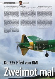
<strong>Valbella</strong> <strong>2000</strong> <strong>BMI</strong> # 11620ManualWARNING - THIS IS NOT A TOY! Radio controlled model aircraft are capable of inflicting serious injury and/orproperty damage if not assembled, operated and maintained in a competent and safe manner. The successfulassembly, operation and maintenance of radio controlled model aircraft are not intuitive skills and performing themsafely and competently takes experience. If you are not already an experienced radio controlled aircraft modeler,we strongly suggest that you find someone who is, to inspect your completed model, to teach you to fly and topoint out the proper maintenance procedures to keep your model aircraft in safe operating condition.Instruction ManualCongratulations on your purchase of this excellent almost ready to fly 4-ch radio controlled electric aerobatic glider!Nevertheless, because of its un-usual aileron-control system, you have to read the instruction manual thoroughlyand carefully before starting the final assembly and installation, especially installing the servos and connectingthe aileron control-rods.SpecificationsWing span: <strong>2000</strong>mmWing area: 34.6 dm²Length: 1024mm.Weight(max.): 1430g.Motor: 550(or 600) direct driveFolding prop: 8"× 4"Power: 7-cells ~ 8.4V/ 1300-3300 mAh.Kit highlights1. One-piece blow-molded fuselage.2. Conventional rib &spar frame structure wing and tail-surfaces, covered with quality Chinese film.3. Easy to assemble and dis-assemble for transportation.4. Semi-symmetric airfoil for fully and easy aerobatics.5. When trimmed properly, hands-off stability and glides right side up as well as up side sown.RequirementsTo complete your Kit, you only need:1. One set of 4-ch radios (with 2 std. servos and 2 micro servo).2. An on/off switch or a proportional speed controller.3. A charger.4. Power-pack 7-cells ~ 8.4V/ 1300-3300 mAh. Nicad or NiMH rechargeable battereisParts ListRefer to Fig. (1), inspect all the parts carefully, please call your shopkeeper immediately if any parts are missingor damaged. The parts and sub-assemblies are shown in the illustrations:1. Left and right wing panels with ailerons hinged.2. The wing dihedral joiner (a straight steel rod)3. Two wing hold-down plastic bolts (with nuts built in fuselage).4. An adhesive tape to seal the joint of wing panels.5. A stabilizer with elevator hinged.6. The fin with two long bolts built-in it and elevator hinged.www.bmi-<strong>models</strong>.com 1
7. Two long plastic nuts to match the built-in bolts in the fix used to fin the complete tail-surfaces in place.8. A one-piece blow-molded plastic fuselage with motor, folding prop, servo-tray, and control linkage allfactory-installed.9. A canopy with two screws and 2 spare ones to fix it onto the fuselage.Fig. (1) Illustration of parts and sub-assembliesFinal Assembly and installation(1)Radio installation:1) Referring to Fig (2). Install the three servos on the servo-tray.2) Connect the servos respectively to the elevator-channel, the rudder-channel and the aileron-channel in thereceiver.3) Install your speed controller (or on/off switch). A slot and a hole are factory-made in the fuselage side foryou to easily install the power switch and the start switch of your speed controller (or on/off switch).4) Insert the battery, into fuselage under the servo-tray AS FAR AFT AS POSSIBLE such that the battery is intouch with the servo IN ORDER TO GET CORRECT C.G. POSITION, otherwise the <strong>Valbella</strong> <strong>2000</strong> will be noseheavy and impossible to fly well. Make sure to secure the battery tightly in place with the Velcro strapssupplied. Remember do not connect the motor to the controller until you are ready to fly.5) Connect the controller to the “throttle” channel in the receiver.6) Set the transmitter to “on” position first and the receiver next. Then, set the power switch of the controllerto “on" position in order to find out the neutral position of the servo horns.7) Always turn-off the receiver first before you turn-off your transmitter.www.bmi-<strong>models</strong>.com 2
control-horn of elevator and rudder respectively.2. The control linkage of ailerons:It is noted that the aileron push-rods are not directly linked with the servo horn. They are linked to anintermediate arm (factory-installed in the fuselage), which in turn is connected to the servo horn byan intermediate push-rod. You just need to connect the “Z-end” of this push-rod to the arm and theclevis of it to the aileron servo horn. And, after mounting the complete wing, connect the clevis ofeach of the aileron push-rod to the aileron-horn.3. Adjustment of push-rods:The affective length of the push-rods can be adjusted by turning the clevis clockwise orcounter-clockwise. The length of push-rods should be adjusted such that when the servo horns are inneutral position, the control-surfaces are also neutral.4. The control stroke adjustment:To increase or decrease the control stroke, you can choose a suitable hole in the servo arm or/and thehole in the control horn. The commended range of movement (i.e. the control stroke) for the elevatoris 15 degrees up and 25 degrees down. And the stroke for ailerons is 15 degrees up and down. Noneed to build differential ailerons for model airplanes.Fig. (4) Illustrations of the control linkage(3) Assembling the wing panels and mounting the complete wing:The <strong>Valbella</strong> <strong>2000</strong> features two plug-in wing panels, which are easily to be assembled and mounted onto thefuselage before flying or dis-assembled after flight for easy transportation.1. Take out the wings and ailerons, slip the hinges into the factory cut hinges slots in the wings and ailerons. Thenbe careful to glue them together by dropping CA into gap at the location of each hinge.2. INSTALL THE AILERON SERVOS ( MICRO SERVO). First, test fit your servos in the aileron servo mounts andenlarge the opening if necessary. There is a string attached to a small wood block, tack glued inside the servoopening. This string leads to the hole in the top of the wing near the root rib, where you will find another woodblock holding the other end. It is used to pull the servo lead wire through the wing. You will need to add aextension to the end of your aileron servo wires. Break the block inside the servo opening loose and pull thestring out a few inches. Cut the string from the block and tie it to the end of the servo extension. Break thewood at the other end of the string loose and pull the string/servo wire through the wing and out the hole inthe top of wing near the root.www.bmi-<strong>models</strong>.com 4
3. Insert the wing dihedral joiner (a straight steel bar) in the hole built-in the root section of each wing panel andjoin the two panels tightly together. Then, apply the supplied adhesive tape to make the joint seamless andairtight.4. To mount the complete wing onto the wing saddle on top of fuselage, note first that there are two metaldowels made inside the fuselage and two holes in the L.E. of the wing. Place the complete wing on the dowelsso as to let the dowels slip into the holes and the complete wing settled in place on the fuselage.5. Insert the two plastic hold-down bolts through the holes in the T.E. of the wing and let the bolts get into thenuts built-in the wing saddle. Finally screw and tighten the two bolts to fix the wing in place.Fig.(5) Assembing and mounting the wingAdhcsive tapeWing hold-down boltsHolesLong steel barDowel suopportDowelsFinal check before flying1. Check the alignment and symmetry of the Kit after final assembly.2. Make sure that the servos operate. When the control sticks are in neutral, the servo horns and control surfacesare also in neutral as well. Adjustment can be made by turning the clevis clockwiseor counter-clockwise to change the effective length of the control-rods so as to get the neutral position of thecontrol surfaces3. Check the movements and direction of the elevator and ailerons.CONTROL SURFACE TRAVEL (Measured at the rear edge.)Ailerons 8mm or 3/8 " each way Elevator 12mm or 1/2” each way4. There is one final step, and this is very important. In order to be controllable in the air, the <strong>Valbella</strong> <strong>2000</strong> mustbalance properly. Make a mark on the bottom of the wing on each side of the fuselage 2 5/8” behind the frontof the wing. . Now try to pick up the airplane using only your fingertips positioned on the marks. If the tailrises higher than the nose, you must add weight to the tail until the airplane will rest level on your fingertips.If the nose rises you must add weight to the nose. Hobby shops and tire stores sell stick-on lead weights forthis purpose.www.bmi-<strong>models</strong>.com 5
5. Radio check as follows:a) Collapse the antenna.b) Before switch on your transmitter, make sure that the throttle stick is at its lowest position.c) Turn on the transmitter first, and then the receiver.d) Move the controls to be sure that they are all functioning correctly.e) Walk away from you model for at least 100feet (30meters) and check all the movements.f) Press the start switch and gradually push forward the throttle stick to check if the speed controller (oron/off switch) is functioning properly.g) Don’t forget to extend the antenna of your transmitter to its full length before you start flying.Flying the <strong>Valbella</strong> <strong>2000</strong>1. Whilst the <strong>Valbella</strong> <strong>2000</strong> will fly in wind up to and over 20 mph, we suggest you choose a day with less than15mph breeze for initial flights. After final double-checking the controls for operation, the motor should beswitched on and the model hand-launched parallel to the ground and directly into the wind. Never throw itupwards, as it may cause the plane to stall and crash before it reaches airspeed.2. Initially keep flying directly into the wind with slightly correcting signals to the ailerons. At the same time themodel should be made to climb with slight up-elevator control if necessary.3. Should the plane has any tendency to turn or dive on its own accord, the movement should be prevented byopposite use of the transmitter controls, and as quick as possible correcting trim control should be applied fromthe transmitter.4. When the model has reached over 100 feet climbing into the wind, you can try a “gently” turn to the left orright to commence a circler to bring the <strong>Valbella</strong> <strong>2000</strong> back to your flying position in repeat a controlled flightback into the breeze. Do not let the model fly “down wing” behind you at any time, until you have become anexperienced pilot.Aerobatics, such as loops and rolls, are easy with the <strong>Valbella</strong> <strong>2000</strong>, once it has been trimmed out for straight andlevel flight. to do loops, merely face the model directly into the wind at a reasonable height. After a gentle diveapply a medium, ”up” elevator, taking it half off at the top of the loop and applying it again as the plane dives onfinal part of the maneuver. Flying directly into the wind and then applying right or left aileron control commencesrolls again. It is important, when the model is half way through its roll and on its back inverted, to give medium“down” elevator to keep the aircraft level. Similarly you can roll the plane upside down and fly inverted providedyou apply the required amount of “down” elevator. Directional control whether flying upright or inverted is easywith the use of aileron movement.<strong>Valbella</strong> <strong>2000</strong> <strong>BMI</strong> # 11620BAUANLEITUNGBedienungsanleitungAchtung, den <strong>Valbella</strong> <strong>2000</strong> ist kein Spielzeug ! Wenn ein R/C Flugzeuge nicht korrekt zusammgengebaut,nicht korrekt geflogen und gewartet wird, könnte es bis zu ernsthaftige Verletzungen und/oderEigentumsbeschädigung führen. Der korrekte Zusammenbau, das Gebrauch sind keine intuitive Fähigkeiten.Diese Fähigkeiten sicher und kompetent durchführen fragt Erfahrung. Wenn Sie nicht bereits ein erfahrener R/CFlieger sind, schlagen wir vor, daß Sie einen erfahrenen Modellierer finden, um Sie zu unterstützen.BauanleitungSie haben sich für ein ausgezeichneter E-Segler entscheiden. Dafür danken wir Ihnen. Um Ihnen den sicherenBetrieb dieses Modells zu erleichtern, sollten Sie unbedingt diese Anleitung vor der erste Inbetreibsnahme genaudurchlesen.Technische DatenSpannweite: <strong>2000</strong> mmTragflächeninhalt: 34.6 Dm²Länge: 1024mm.Fluggewicht (max.) : 1430g.Motor: 550(ou 600) direct driveFaltender Propellor : 8 × 4www.bmi-<strong>models</strong>.com 6
Akkus: 7~8 Zellen 7.2 ~ 8.4V/ 1300-3300 mAh.6. Einteiliger geformter Rumpf.7. Flügelstruktur und Steuerungen in klassischer Konstruktion, bedeckt mit Folie aus Qualitätspolyester.8. Einfache Zusammenbau und Zerlegung für Transport.9. Semi-Symmetrisches Flügelprofil für gute akrobatische Leistungen.10. Wenn den Segler gut reguliert wird, sind die Stabilitätsleistungen so, daß er fliegen kann, ohne die Aufträge zuhandhaben.Hinweise für die AnlageUm den Kit zu kompletieren brauchen Sie folgendes:Orientieren Sie sich vor Baubeginn über die Einbaumöglichkeit der zu verwendenden Fernsteuerung.1. Fernsteuerung, eine Anlage mit 4 Kanälen, 2 Standardservos und 2 Microservo’s (für die Flügel).2. Einen elektronischen Fahrtregler mit Bec – Funktion.5. Ein Akkulader6. Akku mit 7 Zellen ~ 8.4V/ 1300-3300 mAh. NI CAD oder NiMHBaukasteninhaltPrüfen Sie, sich auf das Bild 1 verweisend, aufmerksam alle Stücke. Wenn Teile beschädigt oder fehlend seinsollten, kontaktieren Sie sofort Ihr Einzelhändler. Die Elemente und Teilmengen werden auf den Zeichnungenaufgenommen.www.bmi-<strong>models</strong>.com 7
1. Die rechten und linken Flügel mit Scharnieren2. Der Tragflügelverbinder3. Plastikschrauben für Flügelbefestigung4. Ein Klebstreifen zum Versiegeln die Verbindung der Flügelverkleidungen5. Höhenleitwerk mit Ruder6. Die Flosse mit zwei eingebauten langen Schraubbolzen und schwenkbare Aufzug7. Der geformte Rumpf mit dem Motor, dem faltbaren Propeller, Servohalterung und die montierte Steuerstange10. Bild (1) Abbildung der TeileEndmontierung und Radio-einbau11. Radio-einbau8) Bild 2; installieren Sie die Servos im Servohalterung.9) Schließen Sie die Servos beziehungsweise an die Höhenruder, die Steuerruder und die Quersteuerruder im Empfängeran.10) Bringen Sie Ihren Fahrtregler an (oder AN/AUS-Schalter). Ein Schlitz und eine Bohrung sind in der Rumpfseitefabrikmäßig hergestellt, damit Sie leicht den An/Aus-Schalter Ihres Fahrtregler anbringen11) Setzen Sie die Batterie im Rumpf unter dem Servo-Behälter SO WEIT WIE MÖGLICH NACH HINTEN EIN. Die Batteriesoll so näh wie möglich beim Servo sitzen UM EIN KORREKTES SCHWERPUNKT ZU ERHALTEN. Andernfalls wird dem<strong>Valbella</strong> <strong>2000</strong> zu fiel gewicht auf der Nase haben und schwer sein zu fliegen. Stellen Sie sich sicher, die Batterie mitden gelieferten Klettverschluss fest zu sichern. Erinnern Sie sich um den Motor nicht an den Fahrtregler an zuschliessen, bis Sie bereit sind zu fliegen..12) Die Endstück-Oberflächen zusammenbauen und anbringen.d. Befestigen Sie das Höhenruderhorn und Steuerruderhorn im Platz. Es gibt zwei kleine Bohrungen, die um diePosition der Horne zu lokalisieren fabrikmäßig hergestellt sind.e. Um die Endstückoberflächen auf das Endstücken des Rumpfs anzubringen, sollten Sie die zwei langenSchraubbolzen (in die Flosse eingebaut) durch die zwei Bohrungen im Ausgleicher zuerst einsetzen. Bitte beachtenSie DEN HOHENRUDER 90 GRAD AUFWÄRTS ZU DREHEN, wie gezeigt auf das nächste Bild.www.bmi-<strong>models</strong>.com 8
Die Höhenruder und Seitenruder Schubstange :Schließen Sie das "Z-Ende" des Höhenrudder Schubstanges beziehungsweise an das Servohorn und an den Gabelkopfan das Steuerung-Horn des Höhenrudder und Steuerrudder an.Die Steuergestänge des Querruderssteuer:Beachten Sie daß die Querruderventilstößel nicht direkt mit dem Servohorn verbunden werden. Sie werden mit einemZwischenarm (schon im Rumpf installiert) verbunden den an das Servohorn durch einen Schubstange angeschlossenwird. Sie brauchen nur das "Z-Ende" dieses Schubstanges an den Arm und Gabelkopf des Querruderservohornanzuschließen. Nach der Befestigung des kompletten Flügels, schließen Sie den Gabelkopf von jedem desQuerruderventilstößels an das Querruderhorn an.Die Ruderausschlag-justierung:Um den Ruderausschlag zu erhöhen oder zu verringern, können Sie eine verwendbare Bohrung im Servoarm und/oderdie Bohrung im Steuerhorn beschließen. Der empfohlene Ruderausschlag für den Aufzug (Höhenruder) ist 15 Gradoben und 25 Grad unten. Und der Querruderausschlag ist 15 Grad auf und ab. Man braucht keine verschiedeneQuerruder für Modellbauflugzeuge zu errichten.Bild (4) Abbildung der Steuerstangenf. Montierung von die Flügelverkleidungen und vom kompletten Flügel am Rumpf:Der <strong>Valbella</strong> <strong>2000</strong> hat zwei Einsteckflügelverkleidungen, die mann vor oder nach dem Flug sehr leicht auf den Rumpfangebrengen oder auseinanderbauen kann. Nehmen Sie die Flügel und Quersteuer heraus und gleiten Sie die Scharniere indie Fabrikschnitt-Scharnierschlitze in den Flügeln und Quersteuerrudern. Achten Sie dann darauf, daß Sie Sekundenklebergebrauchen um alles zusammenzukleben (Sekundenkleber im Loch jedes Scharniers fallenlassen).INSTALLIERUNG VOM QUERRUDER SERVOS (MICRO SERVOS). Passen Sie zuerst Ihre Servos in denQuerruderservoeinfassungen und vergrößeren Sie die Öffnung wenn notwendig. Eine Zeichenkette ist innerhalb derServo-öffnung zu einem kleinen hölzernen Block geklebt. Diese Zeichenkette führt zu die Bohrung in der Oberseite desFlügels nahe der Anschlußrippe, in der Sie einen anderen hölzernen Block finden, den das andere Ende haltet. Sie wirdverwendet, um die Servoleitung durch den Flügel zu ziehen. Sie sollen aber wahrscheinlich die Servoleitungen erlängerenmüssen. Brechen Sie dann den Block innerhalb der Servo-öffnung lose und ziehen Sie die Zeichenkette einige Zentimeterraus. Schneiden Sie die Zeichenkette vom Block und binden Sie sie an das Ende der Servoverlängerung. Brechen Sie dasHolz am anderen Ende der Zeichenkette lose und ziehen Sie die Servoleitung durch den Flügel und aus der Bohrung in derOberseite des Flügels nahe der Wurzel.Stellen Sie den V-Stellung Schreiner (einen geraden Stahlstab) in die eingebaute die Sie in jeder Flügelverkleidung ein.Verbinden Sie dann ganz fest die zwei Flügelverkleidungen. Bringen Sie dann den gelieferten Klebstreifen an, um dieVerbingung nahtlose und luftdicht zu machen.www.bmi-<strong>models</strong>.com 9
Bevor Sie den kompletten Flügel auf den Tragflügelauflage anbringen, achten Sie darauf daß es zwei Metalldübel gibt, diesich innerhalb des Rumpfs befinden. Es gibt auch zwei Bohrungen im Nasenleiste des Flügels. Setzen Sie jetzt denkompletten Flügel auf die Dübel. Lassen Sie die Dübel in die Bohrungen gleiten so dass den kompletten Flügel imPlatz auf dem Rumpf vereinbart wird.Setzen Sie die zwei Plastikniederhaltebolzen durch die Bohrungen im Endliste des Flügels ein. Legen Sie dann dieSchraubbolzen in die im Flügelsattel eingebaute Mutter. Schließlich schrauben Sie und ziehen Sie die zwei Schraubbolzenfest, um den Flügel im Platz setzenFunktionsprobe3. Überprüfen Sie die Symmetrie und Abstimmung des Modellflugzeugs nach Endinstallation4. Bringen Sie die Trimmungen am Sender in Mittelstellung. Setzen Sie den Gansknüppel auf „Motor Aus“.5. Überprüfen Sie die Bewegungen und die Richtung des Höhenruder und der Querruder.Bewegung und Richtung (gemessen am hinteren Rand.)Querruder 8mm, Aufzug 12mm jeder Flügel6. Dies ist einer der wichtigste Punkte für gute Flugqualitäten Ihres <strong>Valbella</strong> <strong>2000</strong>. Der Schwerpunkt liegt ungefähr 7 cmhinter der Vorderkante des Flügels. Markieren Sie diese Distanz und setzen Sie Ihr Segelflugzeug ausbalanciert aufdieser Linie. Der <strong>Valbella</strong> <strong>2000</strong> muß leicht von der Nase stechen. Wenn die Nase sich aufhebt, müssen Sie absolutentwerder die Akkus verschieben oder Ballast zum hinteren Teil des Rumpfes hinzufügen.7. Senderüberprüfung :Laden Sie erst den Flugakku und beachten Sie die Anleitung des Ladegeräts und des Akkuhersteller.- Schalten Sie den Sender einn und bringen Sie den Motorschalter in NEUTRAL-Position.- Verschieben Sie die Kontrollen, um sicher zu sein, daß alle richtig funktionieren- Stellen Sie sich hinter das Modell.- Betätigen Sie den Startschalter und drücken Sie die Drosselstöcke stufenweise nach vorn zur Überprüfung ob derFahrtenregler (oder der AN/AUS-Schalter) richtig arbeitet.- Vergessen Sie nicht, die Antenne Ihres Senders vollständig aus zu ziehen, bevor Sie anfangen zu fliegen.Und jetzt fliegen !5. Zum einfliegen des Modells sollten Sie sich einen möglichst windstillen Tag aussuchen. Als Gelände für die ersten Flügeeignet sich ein grosse, ebene Wiese ohne Hindernisse.6. Das Modell zusammenbauen und nochmals eine Funtionsprobe mit Reichweitentest durchführen.7. Nach die Funtionsprobe, welche die Kontrollen für Betrieb doppeltkontrolliert, sollte der Motor eingeschaltet werden unddas Modell mit einem Hand-Start direkt in den Wind, und parallel mit den Boden geworfen werden. Werfen Sie dasFlugzeug nie aufwärts, weil es Absturzen könnte.8. Versuchen Sie zuerst, direkt in den Wind zu fliegen und nur Korrektionen mit den Querrudern zu machen. Gleichzeitigsollte das Flugzeug auch steigen mit leichte Höhenruder Steuerungen.9. Die Reaktionen des Modells auf die Ruderausschläge nach der Landung entsprechend vergrössern oder verkleinen.10. In ausreichender Sicherheitshöhe die Mindestfluggeschwindigkeit erfliegen. Die Landung mit ausreichender Fahrteinleiten.11. War ein Nachtrimmen erforderlich, so werden die Gestängenlängen nach der Landung korrigiert und die Trimmhebel amSender wieder in Mittelstellung gebracht, so dass für die folgenden Flüge beidseitig der volle Trimmweg zur Verfügungsteht.12. Wenn Sie ein gutes Flugniveau erreicht haben, können Sie sich an den laufendsten akrobatischen Darstellungen wieLoopings, Fässer, Umkehrungen und andere versuchen.www.bmi-<strong>models</strong>.com 10
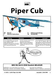
<strong>Valbella</strong> <strong>2000</strong> <strong>BMI</strong> # 11620Manuel d’instructionsAttention ce n’est pas un jouet. Les avions radiocommandés peuvent, vous infliger de sérieuses blessures ou aussicauser de sérieux dégâts matériels si ils ne sont pas réglés et pilotés par des modélistes compétents et responsables.L’assemblage et la mise en oeuvre de ces modèles ne se font pas par intuition mais en respectant les règles recommandéespar le constructeur et si vous manquez d’expérience demandez toujours le concours d’un modéliste expérimenté que ce soit,pour le montage et pour les premiers vols.Manuel d’assemblageFélicitations pour l’acquisition de ce magnifique planeur acrobatique électrique. Afin d’en retirer toute la satisfaction que cemodèle vous procurera, nous vous conseillons de suivre consciencieusement ce manuel et vous demandons une attentionparticulière dans la réalisation des éléments de commande.CaractéristiquesEnvergure : <strong>2000</strong> mmSurface alaire : 34.6 Dm²Longueur : 1024mm.Poids (max.) : 1430g.Moteur : 550(ou 600) direct driveHélice repliable: 8× 4Accus : 7~8 eléments 7.2 ~ 8.4V/ 1300-3300 mAh.1. Fuselage moulé en une pièce.2. Structure d’ailes et gouvernes en construction classique et entoilage film polyester de qualité..3. Assemblage et démontage facile pour le transport.4. Profil d’aile semi symétrique pour de bonnes performances acrobatiques.5. Lorsque l’appareil est bien réglé les performances de stabilités sont telles que la machine peut voler sans manipuler lescommandes.Equipement1. Pour compléter votre kit il vous faut seulement:Une radio 4 voies, avec 2 servos standards et deux servos micro.(ailes)2. Un variateur de type BEC3. Un chargeur d’accus.4. Power-pack 7-eléments ~ 8.4V/ 1300-3300 mAh. NI CAD or NiMH rechargeablesListe piècesVous référant à la fig (1) vérifiez attentivement toutes les pièces et si il y en avait d’abîmées ou manquantes, contactezimmédiatement votre détaillant. Les éléments et sous ensembles sont repris sur les dessins.1. Les ailes droite et gauche avec charnières.2. La clé d’ailes (tige d’acier droite)3. Deux boulons plastique de fixation d’ailes.4. Du ruban adhésif pour la jointure d’ailes.5. Le stabilisateur et gouverne de profondeur avec charnières.6. La dérive comprenant deux longs boulons de fixation.7. Deux longs écrous pour la fixations des éléments de gouvernes arrières au fuselage.8. Le fuselage moulé d’une pièce avec le moteur, l’hélice repliable, la platine servo et les tringles de commandes9. instalées d’usine.10. La verrière avec les vis de fixation pour la mise en place sur le fuselagewww.bmi-<strong>models</strong>.com 11
12. Fig. (1) Illustration des composantsAssemblage final et montage radio(1) installation radio1. Voir fig. (2) installer les trois servos dans leur platine.2. Connectez les servos au récepteur respectivement sur les sorties correspondant à leur fonction. Profondeur, dérive,ailerons.3. Installez votre variateur BEC (ou on/off switch).Un emplacement est prévu d’usine pour le montage d’un éventuelinterrupteur (on/off switch).4. Insérez l’accus dans le fuselage sous, la platine servos. Il est important de bien respecter le centrage de la machine. Sil’accus n’est pas correctement positionné, vous risquez de ne pas avoir le bon centrage et cela pourrait rendre votremachine instable voire incontrôlable jusqu’à la destruction de celle-ci. Après la mise en place correcte de l’accus vérifiezqu’il est maintenu par les bandes de Velcro. Ne laissez jamais vos batteries connectées à l’ensemble lorsque vous nevolez pas. Allumez votre émetteur en premier et ensuite le récepteur (pour des raisons de sécurité respectez toujourscet ordre) .Positionnez les servos au neutre.(2) Assemblage et montage des gouvernes de direction et profondeur.1. Fixez les guignols de profondeur et dérive en place. Les emplacements sont déterminés par des perçages.2. Pour installer le stabilisateur et dérive sur le fuselage, vous devez d’abord insérer les boulons plastique dans leurlogement autrement il serait impossible de réaliser le montage et ne pas oublier de remonter la gouverne deprofondeur de 90° comme montré fig (3)3. Serrez les deux boulons sans forcer contre la surface du fuselage.www.bmi-<strong>models</strong>.com 12
Tringles de commande dérive et profondeur :Connectez les tringles de commande coté Z au palonniers de servos et le coté chappe aux guignols sur lesgouvernes.5. Accessoires pour le contrôle des ailerons:Il faut remarquer que les tringles d’ailerons ne sont pas connectées directement au servos. En effet ils passentd’abord par un bras intermédiaire installé en usine. Passez le coté Z sur la commande d’aileron et le coté chappesur la palonnier de servo.Réglage de la longueur des tringles :La longueur des tringles peut être affinée en vissant ou dévissant la chappe de chaque commande. Vérifierd’abord qu votre servos est en position neutre.6. Contrôle de l’amplitude des mouvements :Pour augmenter ou diminuer la course des gouvernes, si vous ne possédez pas de radio sophistiquée il suffitsimplement de positionner la tringle soit le plus prés de l’axe du servos soit vers l’extérieur.Par exemple pour la profondeur nous recommandons 15 degrés en haut et 25 degrés en bas. Pour les aileronsun débattement de + 15° et – 15° est optimum. Il n’est pas utile d’adjoindre du différentiel à ces gouvernes.Fig. (4) Illustration accessoires de commandes de gouvernes(3) Assemblage des ailes et fixation au fuselage :La conception du <strong>Valbella</strong> <strong>2000</strong> permet le montage et démontage des ailes aisément. Celles ci possèdent des repèressaillants.2. Préparez les ailes et ailerons, insérez les charnières dans les découpes prévues à cet effet. Avec le plus grand soin mettezà chaque charnière une goutte de colle genre Cyano en faisant bien attention de ne pas coller les gouvernes aux ailes.3. INSTALLATION DES SERVOS D’AILERONS4. Vérifier si vos servos rentrent dans leur emplacement et ajuster si nécessaire. Des fils sont passés dans les ailes ainsi quedes petits bouts de bois y sont fixés. Ceci vous facilitera le passage des cordons de servos.5. Insérez la clé d’aile (tige d’acier) dans les trous prévus à cet effet dans les deux panneaux d’ailes. Appliquez le jointadhésif pour la finesse.Pour monter l’aile sur le fuselage faire glisser l’aile sur les deux taquets et les trous prévus bienpositionner l’aile.5. Insérez les deux écrous en plastique dans leurs emplacements respectifs et finalement passez les boulons et serrez .www.bmi-<strong>models</strong>.com 13
Contrôle final avant vol.Vérifiez l’alignement et la symétrie de l’ensemble.1. Assurez vous du fonctionnement des servos. Vérifiez que vos servos et commandes d’émetteur sont bien au pointneutre.2. Vous pouvez ajuster le neutre en vissant ou dévissant la chappe. Vérifiez les mouvements et directions de chaquegouverne.3. Vérification du debattement :Ailerons 8mm. Profondeur 12mm de chaque coté.4. Ceci est un des plus importants points à respecter pour de bonnes qualités de vol de votre <strong>Valbella</strong> <strong>2000</strong>. Le centre degravité se situe à environ 7 cm du bord d’attaque de l’aile. Repérez cette distance et placez votre planeur en équilibre surcette ligne. Il doit légèrement piquer du nez. Si le nez se lève vous devez impérativement soit déplacer vos accus ouajouter du lest à l’arrière du fuselage.Contrôle radio :1. Déployez l’antenne de votre émetteur..2. Avant d’allumer votre émetteur vérifier que la commande des gaz est en position arrêt3. Toujours allumer l’émetteur et ensuite le récepteur.4. Vérifier que les commandes fonctionnent dans le bon sens et sans difficultés..5. Faites un essai de portée de votre radio antenne rentrée l’ensemble doit fonctionner à one distance minimale de 30mètres..6. Vérifier si votre variateur de vitesses fonctionne correctement et à pleine capacité.Faire voler <strong>Valbella</strong> <strong>2000</strong>1. Malgré que le <strong>Valbella</strong> <strong>2000</strong> vole parfaitement dans des conditions venteuses allant jusque 40 Km heure, nous vousconseillons d’éffectuer les premier vols pour une bonne prise en mains et réglage fin par temps calme et clair. Après avoirvérifié le bon sens et fonctionnement des commandes, mettez les gaz à fond et contre le vent et maintenu à plat lancervotre machine jamais le nez en l’air. Aussitôt dans son élément réduisez les gaz et maintenez votre planeur en palierpour vérifier son comportement.2. Lorsque vous aurez acquit un bon niveau de pilotage vous pourrez vous essayer au figures acrobatiques les pluscourantes, telles que loopings, tonneaux, renversements et autres suivant votre imagination et aussi à vous initier auxatterrissages de précisionwww.bmi-<strong>models</strong>.com 14