Fire Damper for Circular Ducts - Halton
Fire Damper for Circular Ducts - Halton
Fire Damper for Circular Ducts - Halton
- No tags were found...

You also want an ePaper? Increase the reach of your titles
YUMPU automatically turns print PDFs into web optimized ePapers that Google loves.
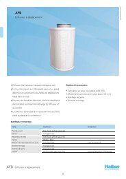
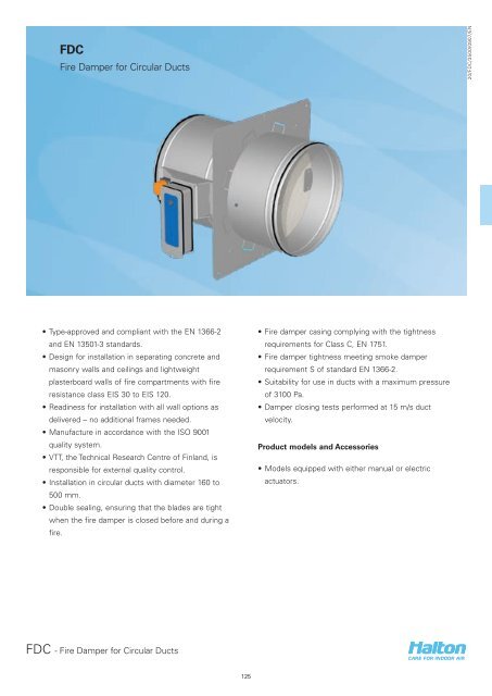
FunctionThe FDC is a circular fire damper of fire resistanceclass EIS 30 to EIS 120, which prevents fire andsmoke from spreading in ventilation ducts. The firedamper is equipped with either a motorised actuatoror manual actuation arrangement. Both actuatorshave a visual position indicator. If the power in themotorised actuator system is switched off, the bladecloses automatically.Europe and Russia models:In both actuator options, a fuse reacts to a rise intemperature, causing a spring-return blade to close.The motorised fire damper is delivered complete witha spring-return actuator and a fuse that is activated at72 ºC.Pressure drop and sound dataSound power level Lw, in in each ocatve band iscomputed bu adding the corresponding correctionfactor, Kok, to the sound pressure level in theselection chart according to the following equation.Lw = LpA + KokThe corresponding factor Kok is the average of theFDC operating area.20/FDC/3500/0907/ENSweden model:The electrical motor option is without thermal fuseand shall be connected to an automatic alarm system.The fire damper is made of fireproof materials. Oncethe fire damper has closed, the double sealing closesthe duct tightly, effectively preventing the spreadingof flue gases in the ventilation ductwork. The flexibleseal of the double sealing system operates at lowertemperatures, while the graphite mass seal expandsto insulate the system at temperatures above 150 ºC.The FDC fire damper can be connected to the MSHcontrol and testing system <strong>for</strong> fire dampers. TheMSH unit enables the use of smoke detectors in theductwork or rooms. The FDC fire damper also canbe connected to other common building automationsystems.f / [Hz] 125 250 500 1k 2k 4k 8kkok 13 7 1 -5 -7 -14 -27l / dB +/- 2 +/- 2 +/- 2 +/- 2 +/- 2 +/- 2 +/- 2FDC - <strong>Fire</strong> <strong>Damper</strong> <strong>for</strong> <strong>Circular</strong> <strong>Ducts</strong>127
InstallationInstallation on concrete and masonry wallsWhen the fire damper is installed on concreteand masonry walls and ceilings between firecompartments, the blade shaft is always horizontal.An opening is always left in the separating element<strong>for</strong> the fire damper, and the product subsequently isgrouted into this.To make installation easier, all products come withan installation flange, which is used to fasten the firedamper to the concrete surface with screws be<strong>for</strong>egrouting.During installation, the fire damper and actuator mustbe protected with, e.g., a plastic cover.The correct operation of the fire damper must beensured be<strong>for</strong>e and after grouting.When the damper is installed on concrete andmasonry walls or ceilings, the size of the installationhole is D+50 mm.Installation on lightweight plasterboard wallsWhen the fire damper is installed on lightweightplasterboard walls between fire compartments,an opening <strong>for</strong> the fire damper must be left in theplasterboard in which the installation frame (includedin the delivery) is first mounted.The blade shaft must always be horizontal.To make installation easier, the fire damper comeswith an installation flange, which is used to fasten thefire damper to, e.g., the steel frame of the panel wall.The space between the fire damper and theinstallation frame is filled with fire prevention mastic.During installation, the fire damper and actuator mustbe protected with, e.g., a plastic cover.The correct operation of the fire damper must beensured after application of the fire prevention mastic.For lightweight walls, the size of the installation holevaries with the specific product; consult the section‘Documents / Installation Instructions’ <strong>for</strong> the size ofthe installation holes.20/FDC/3500/0907/ENDetailed installation instructions, as well as aninstaller’s installation certificate <strong>for</strong>m, are suppliedwith each product. See also the section ‘Documents /Installation Instructions’.Electric actuator wiring diagramManual actuator wiring diagram (limit switches,MS)-~+-~+1 2S1 S2 S3 S4 S5 S61 2S1 S2 S3 S4 S5 S6K1K1K1< 5< 80< 5 < 80Tf1 Tf2 Tf3 LED BAE72B-SBF24-HIBF230-HIBLF24-HIBLF230-HIBF24-T HIBF230-T HIBLF24-T HIBLF230-T HI<strong>Damper</strong> open <strong>Damper</strong> drives <strong>Damper</strong> closedK1:13/14 closed K1: 13/14 open K1: 13/14 open21/22 open 21/22 closed 21/22 closedK2: 13/14 open K2: 13/14 open K2: 13/14 closed21/22 closed 21/22 closed 21/22 openFDC - <strong>Fire</strong> <strong>Damper</strong> <strong>for</strong> <strong>Circular</strong> <strong>Ducts</strong>128
Suggested specificationsA fire damper of class EIS 30 to EIS 120 shall havea double sealing solution that ensures fire-gasresistance at all temperatures when the fire damper isclosed.In motorised models, the fuse shall be activated at 72°C (E and R models).In the manually operated system, the fuse activationtemperature corresponds to the specifications (50, 65,72, 100 °C).The fuse shall be located inside the damper, and itshall be possible to replace it from the outside.The fire damper shall have means <strong>for</strong> external opening/ triggering of the release and closing.The fire damper shall include a position indicator.The fire damper shall be suitable <strong>for</strong> vertical andhorizontal installation on concrete and masonry wallsand on ceilings and lightweight plasterboard wallsbetween fire compartments (EIS 30 to EIS 120).The technical properties of the type-approved firedamper shall con<strong>for</strong>m to the EN 1366-2 and EN13501-3 standards.The internal quality control of the fire dampermanufacturer shall be based on the ISO 9001 qualitysystem, and the operations of the manufacturer shallbe subject to external third-party quality control.Product codeFDC/S-DS = ModelE EuropeS SwedenR RussiaD = Connection size160, 200, 250, 315, 400, 500Specifics and AccessoriesRE = Release typeMA Spring releaseB1 BF-24-T-2 HI, fuse 72°C (E and Rmodels) (D400 ... D500)B2 BF-230-T-2 HI, fuse 72°C (E and Rmodels) (D400 ... D500)B3 BLF24-T HI, fuse 72 ºC (E and Rmodels) (D160 … D315)B4 BLF230-T HI, fuse 72 ºC (E and Rmodels) (D160 … D315)B5 BF-24 HI, no fuse (S model)(D400 ... D500)B6 BF-230 HI, no fuse (S model)(D400 ... D500)B7 BLF24 HI, no fuse (S model)(D160 … D315)B8 BLF230 HI, no fuse (S model)(D160 … D315)20/FDC/3500/0907/ENFU = Fuse release temperature (°C)72 72 °C50 50 °C65 65 °C100 100 °CAC = AccessoriesN1 Safety mesh, 1 side, installed inactuator sideN2 Safety mesh, 2 sidesMS Limit switchesCode exampleFDC/E-160, RE=MA, FU=72FDC - <strong>Fire</strong> <strong>Damper</strong> <strong>for</strong> <strong>Circular</strong> <strong>Ducts</strong>129