
Create successful ePaper yourself
Turn your PDF publications into a flip-book with our unique Google optimized e-Paper software.
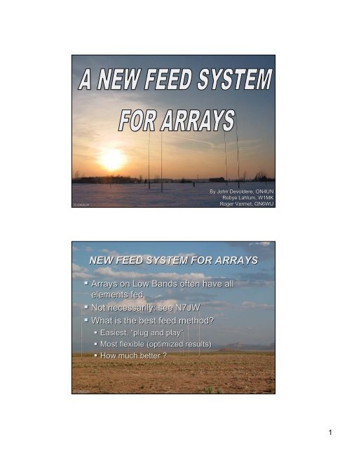
© ON4UNBy John Devoldere, ON4UNRobye Lahlum, W1MKRoger Vermet, ON6WU<strong>NEW</strong> <strong>FEED</strong> <strong>SYSTEM</strong> <strong>FOR</strong> <strong>ARRAYS</strong>• Arrays on Low Bands often have allelements fed• Not necessarily: see N7JW• What is the best feed method?• Easiest, “plug and play”• Most flexible (optimized results)• How much better ?© ON4UN1
PHASING ANGLE & LINE LENGTH• In the past:phase delay =cable length• IS WRONG(in most cases)© ON4UNBREAKTHROUGHS• Forest Gehrke – K2BT- Ham Radio 1983• W2CQH: the hybrid coupler QST Jan 1978© ON4UN2
GEHRKE – K2BT METHODGehrke, K2BT, has developed a technique that is fairlystandard in the broadcast world.Typical K2BT feed system for a 2-ement 2array© ON4UNTHE HYBRID COUPLER(Commercialized by COMTEK)© ON4UN3
OTHER <strong>SYSTEM</strong>S• Many other systems e.g. K3LC, W8JI (crossfire) etc.© ON4UNW7EL’s s BREAKTHROUGH• W7EL current forcing• Covered in great detail in ARRL Antenna book• Property of a quarter wave long feed line:I(at ant) = E (at end line) / Zcable• I(at antenna) determines radiation (not E!)• E is easier to measure than I• So: measure E at the end of a ¼ wave line© ON4UN4
NOW: FULL DESIGN FREEDOMW7EL L <strong>net</strong>work → W1MK L <strong>net</strong>work• Until now formulas available only for quadrature feedbut with any feed current magnitude( Quadrature = in increments of 90 deg )• Now W1MK developed the mathematics that applyfor any magnitude and phase angle• It really is a Gehrke equivalent (= FULL DESIGNFREEDOM) where all <strong>net</strong>works are combined in asingle L <strong>net</strong>work© ON4UNWHY?• Why do we want “any” magnitude and phaseangle?• More design freedom for improved performance• Let’s s analyze the well known 4-square array© ON4UN5
OPTIMIZED VS. QUADRATURELEFT:Quadrature feed withequal currentsBack:1A at 0 degCntr: 1A at -90 degFrnt: 1A at -180 degRIGHT:G = 6.7 dBi, RDF = 10.6 dB, DMF = 21.0 dB© ON4UNWA3FET feedBack:1A at 0 degCntr: : 0.9A at -111 degFrnt: : 0.872A at -218degG = 7.2 dBi, RDF = 11.4 dB, DMF 24.0 dBQuadrature feedCan be calculated with W7ELformulas from ARRL AntennaBookQUADRATUREOr you can use a hybrid coupler!© ON4UN6
FULL FREEDOMOdd phase angles (non quadrature)• No calculation tool so far• Now the mathematics and a user tool areintroduced by W1MK© ON4UNWA3FET OPTIMIZED <strong>FEED</strong>• Networks to be calculatedwith W1MK’s s formulas• Used in a user friendlyExcel spreadsheet© ON4UNW1MK7
EQUATIONS <strong>FOR</strong> ANYAMP/PHASEW1MKCOMPARISONW1MK8
THE SPREADSHEET TOOL (1)CALCULATION L-NETWORK <strong>FOR</strong> LEWALLEN / LAHLUM <strong>FEED</strong>For system using current forcingINPUT DATAn elem1n-elem: if single line, enter 1, if dual line, enter 2, etcZo75.00ohmZk of current forcing feed linesR36.60ohmresistive part of impedance of elem fed through L <strong>net</strong>workX69.40ohmreactive part of impedance of element fed through L <strong>net</strong>workk0.87current magnitude coefficienttheta-218.00degTheta = phase shift to be obtained with the L-<strong>net</strong>workfreq1.83MHzfrequencyRESULTSX-Series-108.51ohmreactance of series element in L-<strong>net</strong>workX-Par33.46ohmreactance of parallel element in L-<strong>net</strong>workSeries elem801.9pFPar elem2.9uHRpar202.12ohmResistive part of parallel impedance at input of L-<strong>net</strong>workXpar-64.31ohmReactive part of parallel impedance at input of L-<strong>net</strong>workRser18.58ohmResistive part of parallel impedance at input of L-<strong>net</strong>workXser-58.40ohmReactive part of parallel impedance at input of L-<strong>net</strong>work© ON4UNTHE SPREADSHEET TOOL (2)CALCULATION L-NETWORK <strong>FOR</strong> LEWALLEN / LAHLUM <strong>FEED</strong>For system using current forcingINPUT DATAn elem2n-elem: if single line, enter 1, if dual line, enter 2, etcZo75.00ohmZk of current forcing feed linesR33.10ohmresistive part of impedance of elem fed through L <strong>net</strong>workX0.00ohmreactive part of impedance of element fed through L <strong>net</strong>workk0.90current magnitude coefficienttheta-111.00degTheta = phase shift to be obtained with the L-<strong>net</strong>workfreq1.83MHzfrequencyRESULTSX-Series88.14ohmreactance of series element in L-<strong>net</strong>workX-Par-63.04ohmreactance of parallel element in L-<strong>net</strong>workSeries elem7.7uHPar elem1380.3pFRpar104.90ohmResistive part of parallel impedance at input of L-<strong>net</strong>workXpar66.65ohmReactive part of parallel impedance at input of L-<strong>net</strong>workRser30.17ohmResistive part of parallel impedance at input of L-<strong>net</strong>workXser47.48ohmReactive part of parallel impedance at input of L-<strong>net</strong>work© ON4UN9
THE 180 DEGREE LINEYou can also feed the front elementthrough a 180 (half wave) line, inwhich case The L <strong>net</strong>work will add218 - 180 = 38 deg of phase shiftINPUT DATAn elemZoRXk175.0036.6069.400.87ohmohmohmtheta-38.00degfreq1.83MHzRESULTSX-Series108.51ohmX-Par87.34ohmSeries elem9.4uHPar elem7.6uHRpar202.12ohmXpar346.84ohmRser150.88ohmXser87.93ohm© ON4UNGETTING PRACTICALAfter the PAPERWORK, let’s s DO it.• Our goal:• Rebuild the ON4UN 4-square 4(80m)• Install a hybrid coupler system• Develop, build and test a Lewallen/Lahlumsystem• Measure current and phase on both systems• Assess and evaluate results of both systemsThank you Jay, WX0B, for helping with theone of your 4-square 4boxes boxes© ON4UN10
EXPERIMENTS AT ON4UN• Rebuild the 4-square4• New elements• New feed points• New quarter-wavefeed lines• Switcheable to 3.505or 3.795 MHz© ON4UNTHE ON4UN 80M 4-SQUARE4© ON4UN11
THE ON4UN 80M 4-SQUARE4© ON4UNDESIGNING THE NETWORK• Calculating the Lahlum-Lewallen Lewallen <strong>net</strong>work• Model the array (Eznec)• Build the array• Resonate the elements• Measure the Z = R at resonance for each element(should be close)• Model a single element• Add Rloss (as a series R at the feed point) to obtainsame feed impedance as measured• Remodel the array with these loss resistors• Plug in the Z obtained Z-values Zin the Lahlumspreadsheet tool© ON4UN12
THE MODEL© ON4UN<strong>FEED</strong> <strong>SYSTEM</strong> AFTER MODEL© ON4UN13
WORK IN THE WORKSHOPWHY?• Verify the feasibility of the L-<strong>net</strong>works Lapproach• Develop an appropriate test and measurementmethod, to adjust the values of the L <strong>net</strong>works• Evaluate the test methodIn a first iteration this was done on dummy loads(also to stay out of the rain…)© ON4UNTHE DUMMY LOADSBuild dummy loadsrepresenting the compleximpedances at the end ofthe quarter-wave feed lines97 ohm234-j127 ohm66-j62 ohmThe loads are capable of dissipatinghundreds of Watts.© ON4UN14
THE LC NETWORKSBuild an LC box with twovariable L’s L s and twovariable C’sC© ON4UNTHE ALIGNMENT TOOLTHE SCOPE PROCEDURE• Use a multi channel oscilloscope• Simultaneously visualize the voltages atthe end of the quarter-wave feed lines• Voltage = antenna feed current x Zcableplus 90 degree phase delay© ON4UN15
THE MULTI CHANNEL SCOPEWe used a 5 channel 100 MHz scope (Kikusui(- modelCOS6100M )Available on Ebayfor approx. $200A 3 channelscope is really allyou need …© ON4UNTHE SCOPE PATTERN• CH3 is the reference signal (back element)• CH2 is the signal going tothe center elements• CH1 is the signal going tothe front element© ON4UN16
© ON4UNTHE VOLTAGE SAMPLINGSamplers:Zload = 12.5 k, attenuation is 12500/25 = 500 = - 54 dBChannel 3: the referencesignal going to the backelement (no <strong>net</strong>work)Channel 2: the measuredsignal at the output of LC<strong>net</strong>work going to the centerelementsChannel 1: the measuredsignal at the output of LC<strong>net</strong>work going to the frontelementThe LC components aretuned until the required phaseshift and voltage areachieved.© ON4UN17
THE SCOPE PATTERNJust a drawing …MADE WITH© ON4UNTHE SCOPE PATTERNOn the multi-channel scopeMADE WITH© ON4UN18
<strong>NEW</strong> <strong>FEED</strong> <strong>SYSTEM</strong> <strong>FOR</strong> <strong>ARRAYS</strong>© ON4UNSCOPE PROCEDURE• Dummies: 230 – j 120, 97 and 66 – j 62 ohm• L1, C1: to center elements, L2, C2 to front elementL1(ser)C1 (par)L2 (ser)C2 (par)model3.4 uH680 pF1.9 uH165 pFdummy3.4 uH818 pF1.4 uH530 pF• Feed impedance: 19.7 + j 8 ohm© ON4UN19
A CONCLUSION• ALIGNMENT PROCEDURE WAS VALIDATED• ALIGNMENT EASY BUT CRITICAL (TOUCHY)NEXT STEP:WAIT <strong>FOR</strong> BETTER WX AND GO OUT IN THE FIELD© ON4UN© ON4UN20
SCOPE METHOD• All tests were done on 3.505 kHz• Disconnect original coils and capacitors• The LC box was placed right next to it andconnected into the WX0B switching box• Alignment using the scope method was VERYeasy, and SEEING the magnitude and phasemade it easy to cope with the effects of mutualcoupling© ON4UN21
LC NETWORK DIAL SETTINGSC1L1C2L2NW31.6625.631732.83SE30.9425.311935.16NE29.9026.111734.69SW31.2925.281633.13FINAL30.8325.6617.534.22VALUES3.3 uH283 pF867 pF1.6 uH22
VARIATIONS IN AMP AND PHASETARGET1.11-111º1.66-218ºK1ϕ1K2ϕ 2NW1.01-115º1.52-210ºSE1.15-111º1.68-222ºNE1.19-111º1.66-222ºSW1.08-118º1.69-218ºAccuracy: phase +/- a few degrees, amplitude +/- 2 %IN REALITYINFLUENCE OF LESS THAN PERFECT RESULTSNE (4.63 dBi)NW (4.57 dBi)Quadrat. (4.15 dBi)PERFECT MODELSE (4.70 dBi)SW (4.67 dBi)Quadrat. (4.08 dBi)MEASURED CURRENTS23
IN REALITYINFLUENCE OF LESS THAN PERFECT RESULTSSUMMARY:Quadrature (hybrid):
OPERATIONAL BANDWIDTH3.5003.520• 3.540K11.151.111.05ϕ1-102°-111°-120°K21.61.661.70ϕ2-210°-218°-230°• OPERATIONAL BW: ~ 50 kHz• SWR = 1/1 OVER APPROX. 100 kHz• SWR BW IS NO VALID PER<strong>FOR</strong>MANCECRITERIONOPERATIONAL BANDWIDTHPATTERNS VS. FREQUENCY3500 Khz (4.64 dBi) 3520 kHz (4.62 dBi) 3540 KHz (4.61 dBi)25
CONCLUSION ON SCOPEPROCEDURE• HIGH DRIVING POWER REQUIRED (100 W)BECAUSE OF “LOW” SCOPE SENSITIVITY• EXCELLENT HUMAN INTERFACE (YOU SEEWHAT YOU DO)• SUFFICIENT ACCURACY IN VIEW OFDIFFERENCES BETWEEN DIRECTIONS(SLIGHT DIFFERENCES IN ELEMENT SELFAND MUTUAL IMPEDANCES)© ON4UNMORE CONCLUSIONS• L NETWORK COMPONENTS MUST BECONTINUOUSLY ADJUSTABLE• ARRAY ELEMENTS ARE NOT “IDENTICAL”• ACCURACY OF ALIGNMENT METHOD SHOULDNOT BE “MUCH” BETTER THAN VARIATION INELEMENT IMPEDANCES (don’t t measure a milewith a micrometer)26
BUILDING A <strong>NEW</strong>HIGH POWER <strong>SYSTEM</strong>• CONTINOUSLY VARIABLE CAPS: VACUUMVARIABLES• CONTNUOUSLY VARIABLE INDUCTORS →VERY BULKY <strong>FOR</strong> HIGH POWER• THE SOLUTION:IS IN “THE BOOK” :TURNING A C INTO AN LCenter elements:target L: 75 ohm or 3.4 uHTop of tuning range = 4.6 uH → 100 Ω1200 pF = -38 ΩCoil: 100 + 38 = 138 ohm → 6.3 uHFront elementTarget L: 35 ohm or 1.6 uHTop of tuning range = 3 uH → 65 Ω1200 pF = -38 ΩCoil = 65 + 38 = 103 Ω→4.7 uH27
THE <strong>NEW</strong> <strong>FEED</strong> BOX• USING FOUR 1200 pF VACUUM VARIABLESEQUIPED WITH TURN COUTERS• VACUUM VARIABLE C IN SERIES WITH AN“OVERSIZED” COIL TO <strong>FOR</strong>M A VARIABLE L• RELAY MATRIX SWITCHING TO PROVIDEMAX. SYMMETRY AND FLEXIBILITY• SEPARATE INPUT MATCHING L-LNETWORKS<strong>FOR</strong> 4-SQUARE 4AND OMNIDIRECTIONAL© ON4UNTHE <strong>NEW</strong> BOX SCHEMATIC© ON4UN28
THE <strong>NEW</strong> BOXTHE <strong>NEW</strong> BOX29
THE <strong>NEW</strong> BOXTHE <strong>NEW</strong> BOX30
THE <strong>NEW</strong> BOXTHE <strong>NEW</strong> BOX31
THE <strong>NEW</strong> BOXINSTALLING AND TUNING32
INSTALLING AND TUNINGINSTALLING AND TUNING33
INSTALLING AND TUNINGINSTALLING AND TUNING34
MEASURED WITH NETWORKANALYZERTARGET1.11- 111 º1.66- 218 ºON 3.5 MHzNWSENESWK11.081.31.21.16ϕ1-116º- 108 º- 103 º- 109 ºK21.691.751.721.69ϕ 2- 226 º- 225 º- 223 º- 226 ºAccuracy: phase +/- 1º, , amplitude +/- 1 %Measurements done using an HP <strong>net</strong>work analyzerIMPORTANT !IMPORTANT TO REMEMBER:• YOU MUST MODEL YOUR ANTENNA ASPRECISELY AS POSSIBLE• THIS WILL GIVE YOU APPROXIMATE L-NETWORKLVALUES• YOU NEED TO ADJUST THOSE IN THE FIELD• CONTINUOUSLY ADJUSTABLE L AND CELEMENTS ARE A MUST• A 3 CHANNEL SCOPE IS A GOOD TOOL35
W1MK HYBRID ALIGNMENT SETUPThis setup is used in conjunction with the W1MK detector /power meter• A null method (bridge method)• Using a hybrid coupler <strong>net</strong>workTo NULL DETECTORFROM ELEMENT 2FROM ELEMENT 1© ON4UNAlready described in edition 3 of Low Band Dx-ingW1MK36
W7EL PHASE ADJUSTMENT(QUADRATURE)EE, -90 degIXA¼ wave LineZoRXXA = Zo^2/RXBR20k90 degHyb50 ohmR20kXB=XA Zo^2/( XXa-Zo^2)I = -j E/Zo50 OHM RF DETW1MKQUADRATURE HYBRID BRIDGEE, -90 deg50 ohmSum50 ohmHYBnullDET50 ohmVoltmeter50 ohmE, 0 degW1MK37
ERROR PLOTW1MKNON QUADRATURE SETUPWA3FET -111 DEG PHASE ANGLEEkE, -111 degIR20kAttXAXBR20k¼ wave LineZoRX-21deg50 ohm90 degHyb50 ohm DetW1MK38
NON QUADRATURE SETUPkE, -111 degCENTER ELEMENT50 ohmSum50 ohmHYBnullDET50 ohmVoltmeterBACK ELEMENTAtt50 ohmE, O deg -21 deg KE, -21 degW1MKNON QUADRATURE SETUP.9E, -111 degCENTER ELEMENT-17 deg .9E , -128 deg50 ohmSum50 ohmHYBnullDET50 ohmVoltmeterFRONT ELEMENT50 ohm.9E, -218 deg.9E, -218 degW1MK39
W1MK DUAL POWER METER-DETECTORper W7ZOI© ON4UNW1MKW1MK DUAL POWER METER-DETECTORper W7ZOI© ON4UNW1MK40
W1MK DUAL POWER METER-DETECTORDirect dBm converter (per N3NHI)© ON4UNW1MKW1MK ALIGNMENT SETUPADVANTAGES• SMALL DRIVING POWER REQUIRED (1 W)• BATTERY POWER OPERATED• INEXPENSIVE TEST/MEASURING EQUIPMENT• NULL METHOD = INCREASED ACCURACY© ON4UNW1MK41
W1MK ALIGNMENT SETUPDRAWBACKS• VISUALLY “LESSINSTRUCTIVE”CONCLUSION• SCOPE AND NULL-METHOD IN REALITYHAVE COMPARABLE ACCURACY© ON4UNW1MK© ON4UN42
WHAT IS IMPORTANT• IDENTICAL ELEMENTS• AVOID COUPLING WITH OTHER ANTENNAS• ERECT THE ARRAY IN THE CLEAR• QUARTER WAVE LINES MUST BE λ/4 (ATBOTH BAND ENDS)• BUILD THE ARRAY WITH GREAT CARE• CAREFULLY ADJUST L NETWORK USINGSCOPE OR W1MK HYBRID SETUP© ON4UNCOMPARINGTHE HYBRID (COMTEK)ANDTHE LAHLUM <strong>SYSTEM</strong>43
THE HYBRID COUPLERTARGET1.0-90º1.0-180ºNWSENESWK11.021.011.01.0ON 3.5 MHzϕ1-106º- 96 º- 93 º- 100 ºK21.01.031.021.0ϕ 2- 186 º- 188 º- 187 º- 186 ºAccuracy: phase +/- 1 degree, magnitude +/- 1 %Measurements done using an HP <strong>net</strong>work analyzer on a Comtek unit44
THE HYBRID COUPLERTARGET1.0-90º1.0-180ºNWSENESWK11.21.01.241.07ON 3.8 MHzϕ1- 92- 92- 86- 93K21.021.071.071.06ϕ 2- 192 º- 192 º- 193 º- 194 ºAccuracy: phase +/- 1 degree, magnitude +/- 1 %Measurements done using an HP <strong>net</strong>work analyzer on a Comtek unitTHE HYBRID COUPLEROPERATIONAL BANDWIDTH• OPERATIONAL BW: > 300 kHz (on 80m)• SWR BW > 300 KHz• POWER IN DUMMY LOAD: < 80 W on 3.5 MHz and< 25 W on 3.8 MHz (for 1.5 KW input)… IF ELEMENTS AND QUARTER-WAVE <strong>FEED</strong>LINES ARE ALTERNATIVELY TUNED TO LOWEND (CW) OR HIGH END (SSB) OF THE BAND45
THE HYBRID COUPLER(Comtek unit)• “PLUG AND PLAY”• BROADBAND (CW and Phone on 80m if quarterwave feed lines are “retuned”)• RELIABLE• NOT EXPENSIVE• NO NEED <strong>FOR</strong> ALIGNMENT….. BUT QUADRATURE ONLY© ON4UNTHE LAHLUM <strong>SYSTEM</strong>• POTENTIAL <strong>FOR</strong> 0.7 dB MORE GAIN ANDIMPROVED DIRECTIVITY• FAIRLY NARROW OPERATIONAL BANDWIDTH:CW AND PHONE ON 80: NEED TO “TUNE” THE QUARTER-WAVE <strong>FEED</strong> LINES AND ADJUST THE L-NETWORKS!L• REQUIRES ALIGNMENT IN THE FIELD… BUT FULL DESIGN FREEDOM (ANY ANGLE ANDMAGNITUDE) and THE ONLY SOLUTION <strong>FOR</strong>MANY <strong>ARRAYS</strong> OTHER THAN 4-SQUARES4© ON4UN46
<strong>NEW</strong> <strong>FEED</strong> <strong>SYSTEM</strong> <strong>FOR</strong> <strong>ARRAYS</strong>WRAP UP• W1MK DEVELOPED THE MATHEMATICS GIVING FULLDESIGN FREEDOM (ANY MAGNITUDE/PHASE)• THE LAHLUM <strong>FEED</strong> <strong>SYSTEM</strong> WAS APPLIED TO ON4UN’S S 4-4SQUARE• SUITABLE ALIGNMENT METHODS WERE DEVELOPEDAND DOCUMENTED• A <strong>NEW</strong> FULLY FLEXIBLE <strong>FEED</strong> BOX WAS DESIGNED ANDCONSTRUCTED• TESTING WAS DONE ON BOTH QUADRATURE (HYBRID)AND LAHLUM (OPTIMIZED AMP/PHASE) CONFIGURATION• CONCLUSIONS WERE DRAWN© ON4UN<strong>NEW</strong> <strong>FEED</strong> <strong>SYSTEM</strong> <strong>FOR</strong> <strong>ARRAYS</strong>THANK YOU,..ROGER, ON6WUANDROBYE, W1MK© ON4UN47
<strong>NEW</strong> <strong>FEED</strong> <strong>SYSTEM</strong> <strong>FOR</strong> <strong>ARRAYS</strong>© ON4UNBy John Devoldere, ON4UNRobye Lahlum, W1MKRoger Vermet, ON6WU48